Engine Coolant Thermostat Housing Replacement LNF
Removal Procedure
Note: A drain has been provided at the bottom of the water pump for engine block coolant drainage.
- Drain the cooling system. Refer to Cooling System Draining and Filling.
- Drain the coolant from the engine block at the water pump drain. After the coolant has drained, tighten the drain bolt.
- Lower the vehicle.
- Remove the air inlet grille panel. Refer to Air Inlet Grille Panel Replacement.
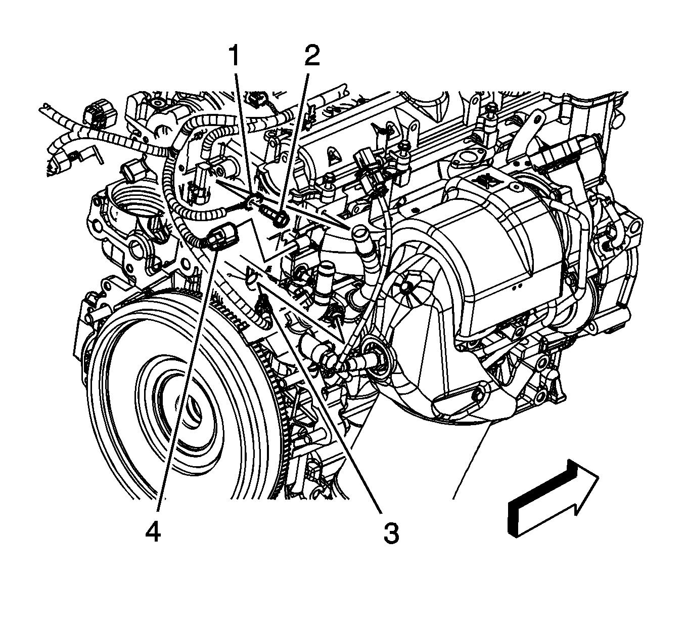
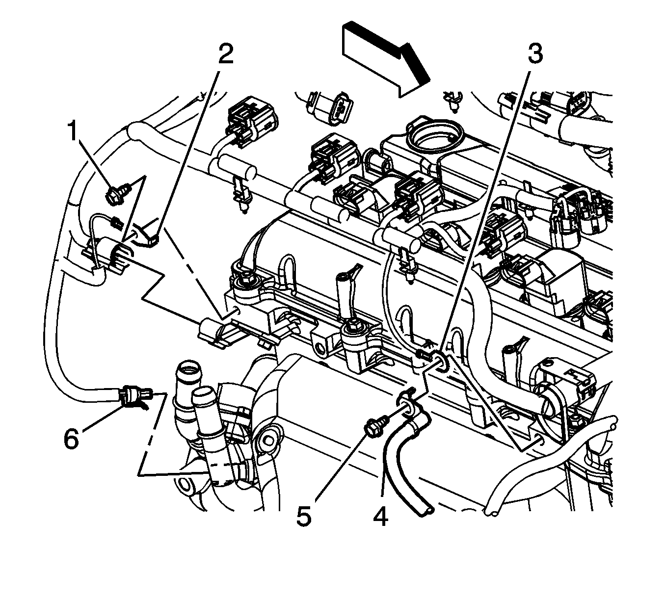
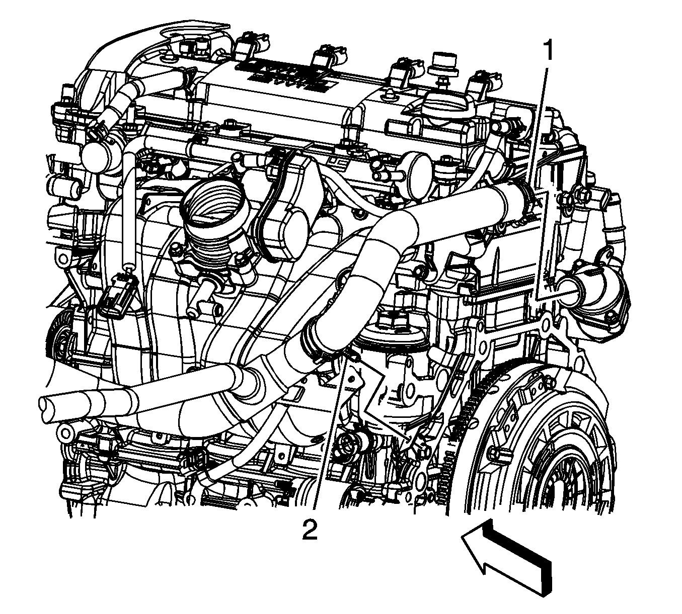
- Disconnect the engine wiring harness electrical connector (3) from the engine coolant temperature (ECT) sensor.
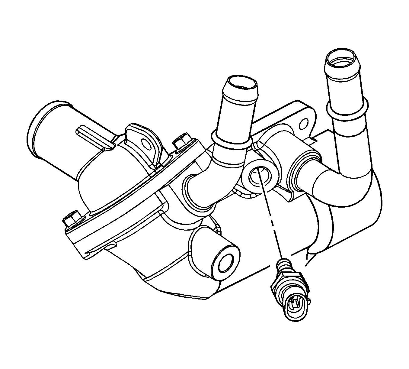
- Remove the ECT sensor, if necessary.
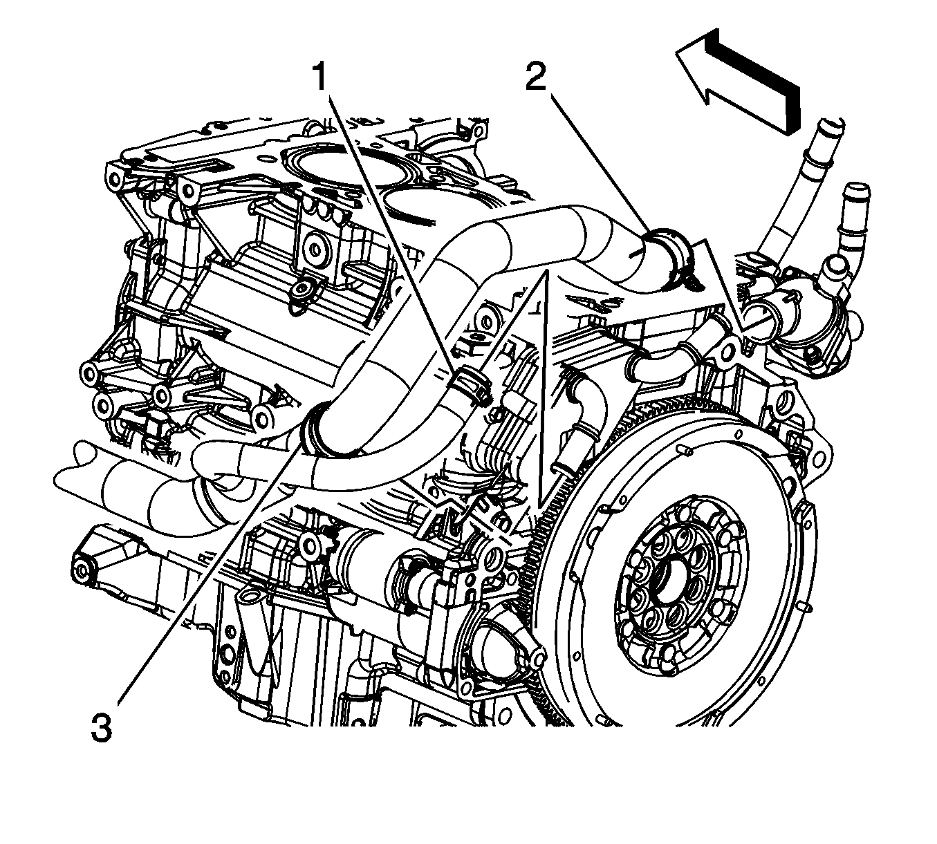
- Reposition the radiator outlet hose clamp (2) at the thermostat housing.
- Remove the radiator outlet hose from the thermostat housing and reposition out of the way.
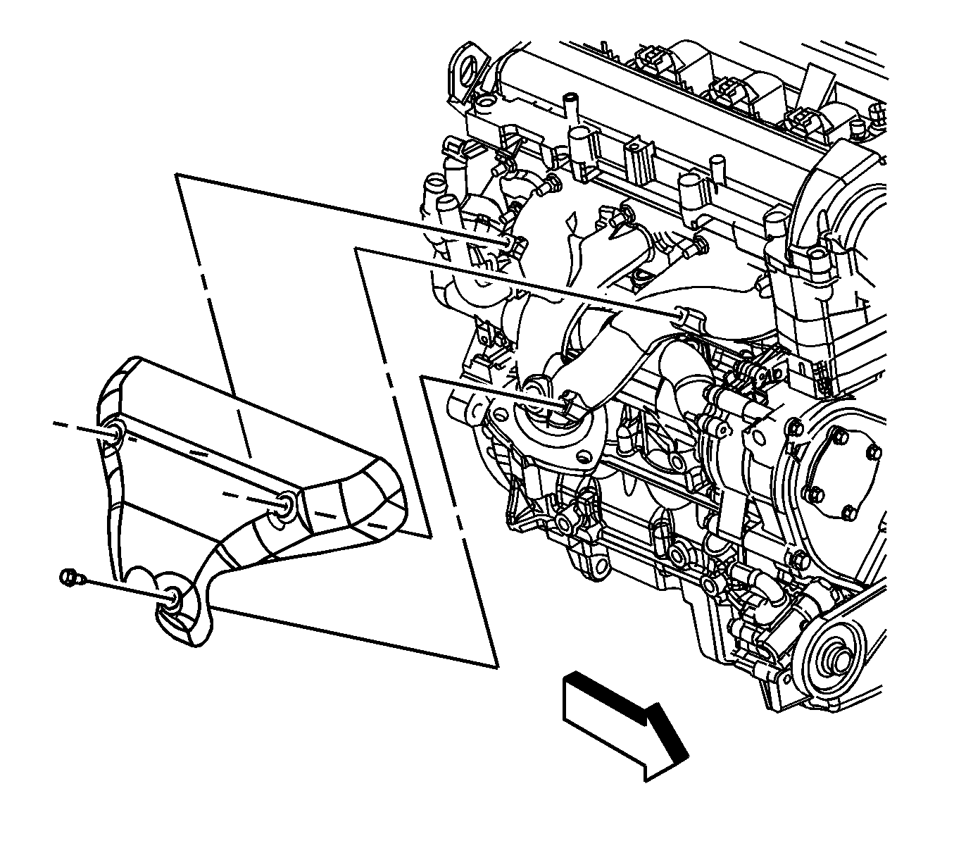
- Remove the exhaust manifold. Refer to Exhaust Muffler Replacement.
- Reposition the heater inlet and outlet hose clamps at the thermostat housing pipes.
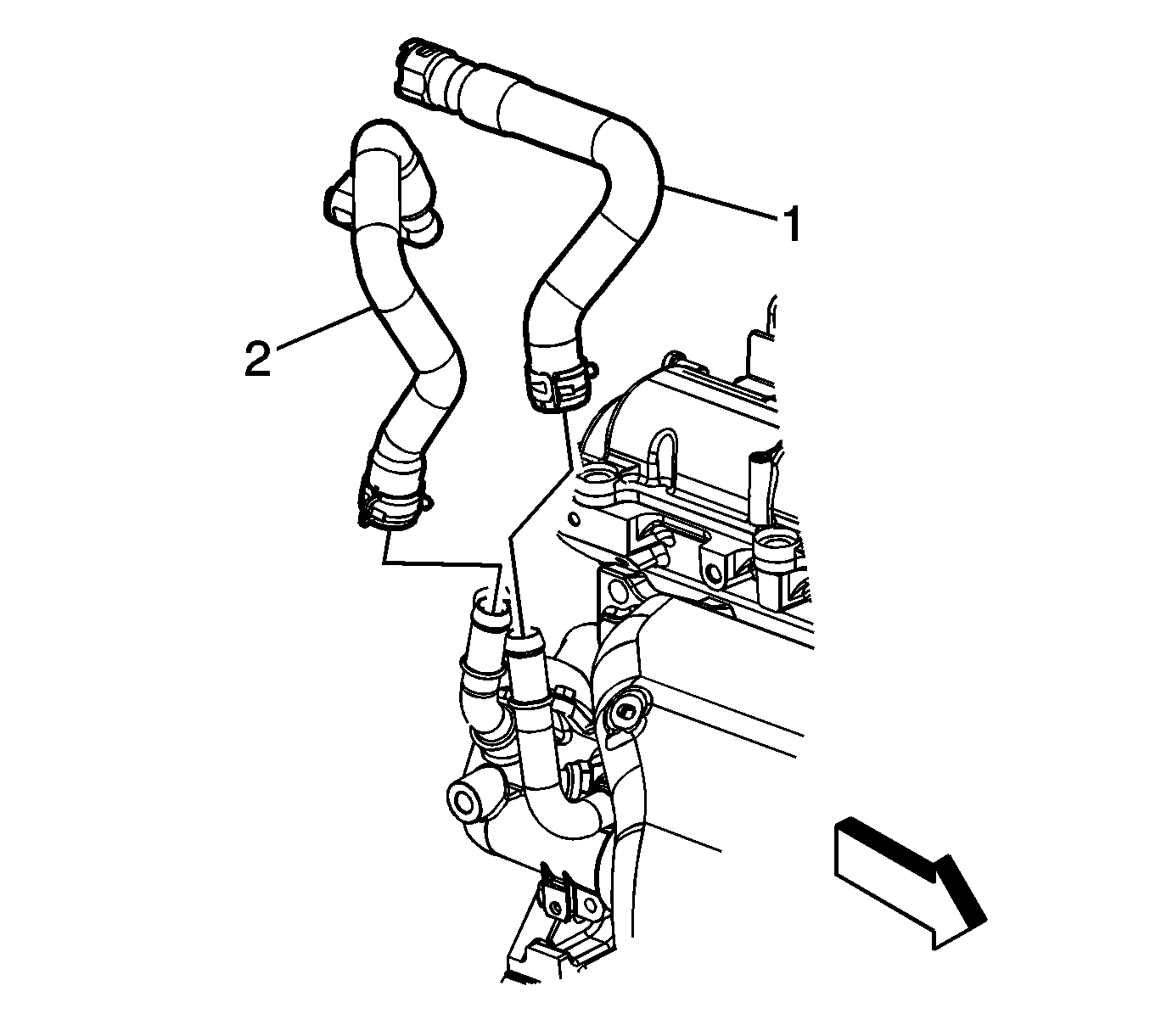
- Disconnect the heater inlet (2) and outlet (1) hoses from the thermostat housing pipes.
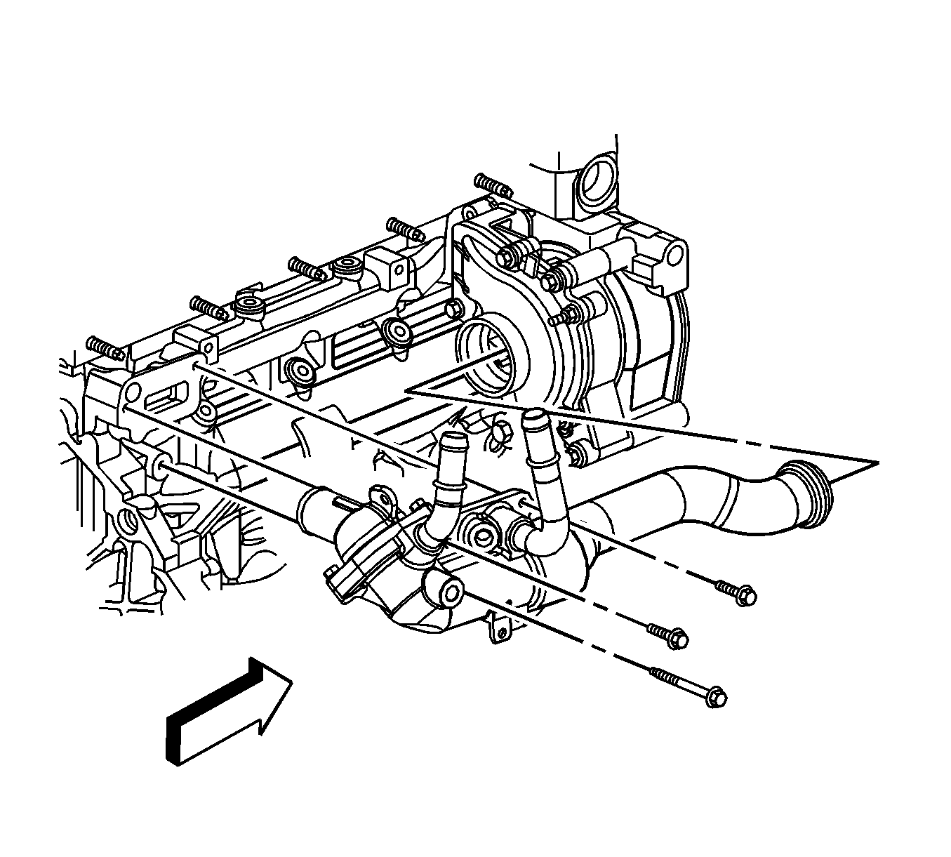
- Remove the thermostat housing bolts.
- Remove the thermostat housing from the vehicle.
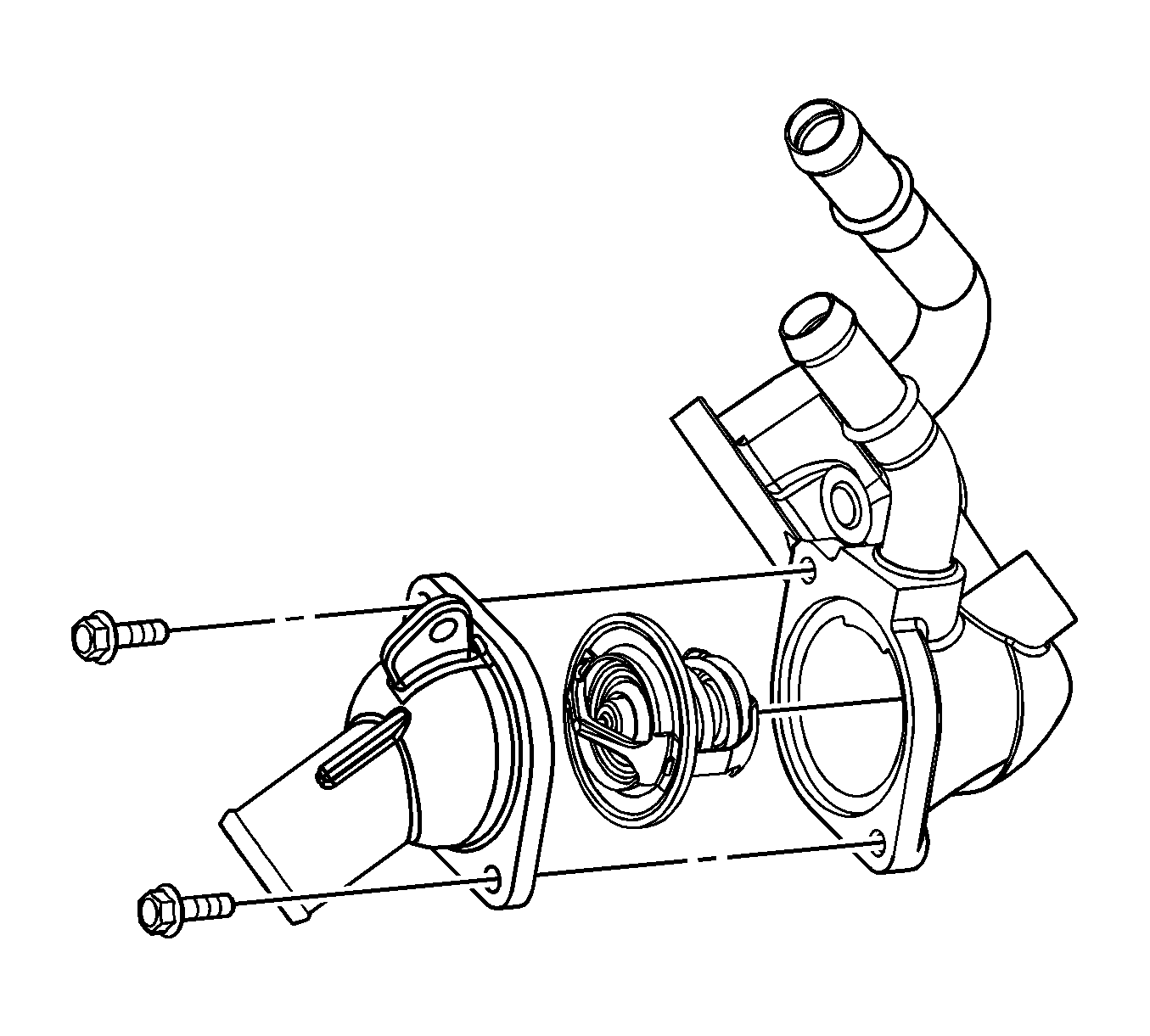
- Remove the water transfer pipe from the thermostat housing, if necessary.
- Remove and discard the water transfer pipe O-ring seals, if necessary.
- Remove the thermostat housing cover bolts and cover, if necessary.
- Remove the thermostat, if necessary.
- Remove and discard the thermostat housing O-ring seal, if necessary.
- Remove all debris and thread sealant from the engine coolant temperature sensor and bolt holes if the housing is being re-used.
Caution: Refer to Fastener Caution in the Preface section.
Tighten
Tighten the drain plug to 20 N·m (15 lb ft).
Note: Twist the water transfer pipe while pulling in order to remove it from the water pump.
Installation Procedure
- Install a NEW thermostat housing cover O-ring seal into the recess groove.
- Install the thermostat, if necessary.
- Install the thermostat housing cover bolts, if necessary.
- Install a NEW thermostat housing to engine gasket onto the thermostat housing.
- Load the thermostat housing assembly into position while the vehicle is lowered.
- Raise and support the vehicle. Refer to Lifting and Jacking the Vehicle.
- Install NEW O-ring seals onto the water feed pipe.
- Install the water feed pipe into the thermostat housing aligning locator tab.
- Align the water pipe to water pump.
- Seat the water feed O-ring seal by pushing inward toward the water pump. Take care not to tear or damage the O-ring.
- Lower the vehicle.
- Position the thermostat housing against the engine.
- Install the thermostat housing bolts.
- Connect the heater inlet (2) and outlet (1) hoses to the thermostat housing pipes.
- Position the heater inlet and outlet hose clamps at the thermostat housing pipes.
- Install the exhaust manifold. Refer to Exhaust Muffler Replacement.
- Install the radiator outlet hose to the thermostat housing.
- Position the radiator outlet hose clamp (2) at the thermostat housing.
- If reinstalling the old sensor, coat the threads with sealant. Refer to Adhesives, Fluids, Lubricants, and Sealers.
- Install the ECT sensor, if necessary.
- Connect the engine wiring harness electrical connector (3) to the ECT sensor.
- Install the air inlet grille panel. Refer to Air Inlet Grille Panel Replacement.
- Verify the drain plugs at the radiator and water pump are tightened.
- Fill the cooling system. Refer to Cooling System Draining and Filling.
- Lower the vehicle.
- Inspect for any leaks.
Caution: Refer to Fastener Caution in the Preface section.
Tighten
Tighten the bolts to 10 N·m (89 lb in).
Note: The water feed pipe seals can be lightly lubricated with coolant to aid during installation.
Note: Lubricate the O-rings with coolant ONLY.
Tighten
Tighten the bolts to 10 N·m (89 lb in).
Tighten
Tighten the sensor to 20 N·m (15 lb ft).
Note: The vehicle must be level when filling the cooling system.
Engine Coolant Thermostat Housing Replacement LE5
Removal Procedure
Note: A drain has been provided at the bottom of the water pump for engine block coolant drainage.
- Drain the cooling system. Refer to Cooling System Draining and Filling.
- Drain the coolant from the engine block at the water pump drain. After the coolant has drained, tighten the drain bolt.
- Lower the vehicle.
- Remove the air inlet grille panel. Refer to Air Inlet Grille Panel Replacement.
- Disconnect the engine wiring harness electrical connector (6) from the engine coolant temperature (ECT) sensor.
- Remove the ECT sensor, if necessary.
- Reposition the radiator outlet hose clamp at the thermostat housing.
- Remove the radiator outlet hose from the thermostat housing.
- Remove the radiator outlet hose clip (1) from the outlet hose bracket.
- Remove the exhaust heat shield bolts.
- Remove the exhaust heat shield.
- Reposition the heater inlet and outlet hose clamps at the thermostat housing pipes.
- Disconnect the heater inlet (2) and outlet (1) hoses from the thermostat housing pipes.
- Remove the thermostat housing bolts.
- Remove the thermostat housing from the vehicle.
- Remove the water transfer pipe from the thermostat housing, if necessary.
- Remove and discard the water transfer pipe O-ring seals, if necessary.
- Remove the thermostat housing cover bolts and cover, if necessary.
- Remove the thermostat, if necessary.
- Remove and discard the thermostat housing O-ring seal, if necessary.
- Remove all debris and thread sealant from the engine coolant temperature sensor and bolt holes if the housing is being re-used.
Caution: Refer to Fastener Caution in the Preface section.
Tighten
Tighten the drain plug to 20 N·m (15 lb ft).
Note: Twist the water transfer pipe while pulling in order to remove it from the water pump.
Installation Procedure
- Install a NEW thermostat housing cover O-ring seal into the recess groove.
- Install the thermostat, if necessary.
- Install the thermostat housing cover bolts, if necessary.
- Install a NEW thermostat housing to engine gasket onto the thermostat housing.
- Load the thermostat housing assembly into position while the vehicle is lowered.
- Raise and support the vehicle. Refer to Lifting and Jacking the Vehicle.
- Install NEW O-ring seals onto the water feed pipe.
- Install the water feed pipe into the thermostat housing aligning locator tab.
- Align the water pipe to water pump.
- Seat the water feed O-ring seal by pushing inward toward the water pump. Take care not to tear or damage the O-ring.
- Lower the vehicle.
- Position the thermostat housing against the engine.
- Install the thermostat housing bolts.
- Connect the heater inlet (2) and outlet (1) hoses to the thermostat housing pipes.
- Position the heater inlet and outlet hose clamps at the thermostat housing pipes.
- Install the exhaust heat shield.
- Install the exhaust heat shield bolts.
- Install the radiator outlet hose to the thermostat housing.
- Reposition the radiator outlet hose clamp at the thermostat housing.
- Install the radiator outlet hose clip (1) to the outlet hose bracket.
- If reinstalling the old sensor, coat the threads with sealant. Refer to Adhesives, Fluids, Lubricants, and Sealers.
- Install the ECT sensor, if necessary.
- Connect the engine wiring harness electrical connector (6) to the ECT sensor.
- Install the air inlet grille panel. Refer to Air Inlet Grille Panel Replacement.
- Verify the drain plugs at the radiator and water pump are tightened.
- Fill the cooling system. Refer to Cooling System Draining and Filling.
- Lower the vehicle.
- Inspect for any leaks.
Caution: Refer to Fastener Caution in the Preface section.
Tighten
Tighten the bolts to 10 N·m (89 lb in).
Note: The water feed pipe seals can be lightly lubricated with coolant to aid during installation.
Note: Lubricate the O-rings with coolant ONLY.
Tighten
Tighten the bolts to 10 N·m (89 lb in).
Tighten
Tighten the bolts to 23 N·m (17 lb ft).
Tighten
Tighten the sensor to 20 N·m (15 lb ft).
Note: The vehicle must be level when filling the cooling system.
