Tools Required
SA9127E-7 Fuel Flow/Pressure Adapter
Caution: Locate class B fire extinguisher in work area.
After it is determined that the fuel system is contaminated, the following procedure to clean it is recommended:
- Place the vehicle on hoist and open the hood.
- Disconnect the negative battery cable.
- Drain the fuel tank.
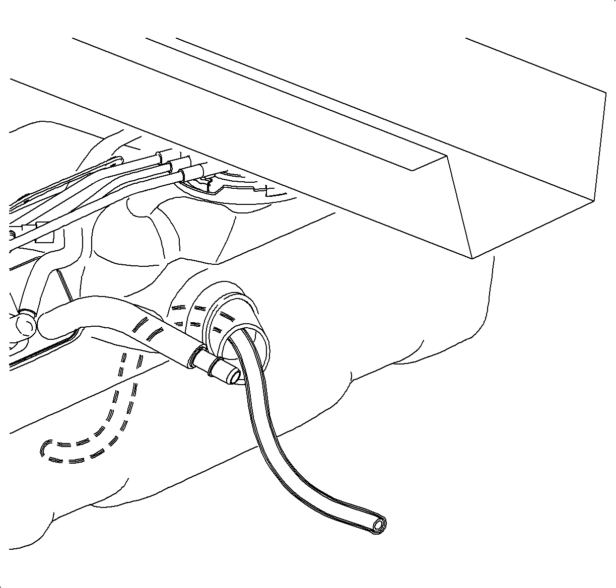
- Remove the fuel tank.
- Disconnect the fuel feed line at the engine.
- With compressed air, blow out the fuel feed line. Catch the fuel in a container at the opposite end of the line.
- Remove the evaporative emissionn (EVAP) canister from the fuel tank.
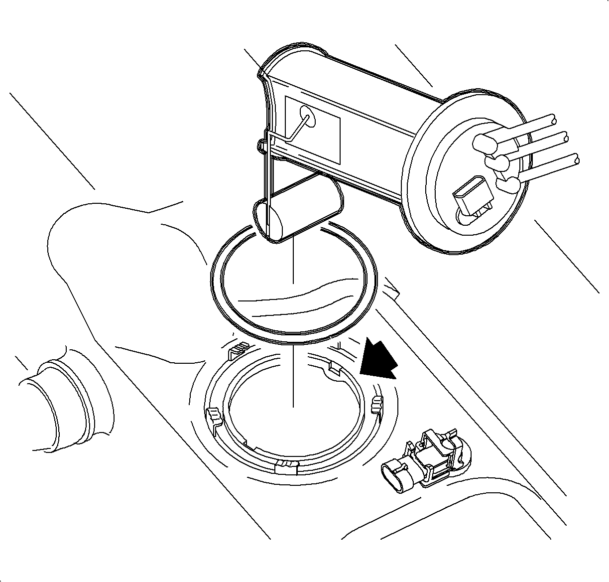
- Remove the pump module.
- Inspect the inlet filter on the pump. If plugged or damaged, the entire fuel pump module must be replaced, not serviced separately.
- Flush the tank with hot water for at least 6 minutes. Invert and drain. All metal chips/debris must be removed from the tank prior to installation.
- Install the EVAP canister to the fuel tank.
- Install the fuel pump module to the fuel tank but do not connect the fuel feed line to the new filter/regulator.
- Install the fuel tank to the vehicle.
- Install the fuel filler pipe to the vehicle.
- Connect the fuel feed line to the fuel rail.
- Put at least 23 L (6 gal) of clean fuel into the fuel tank.
- Connect the negative battery cable.
- Connect the Tech-2 to the vehicle and turn the ignition ON.
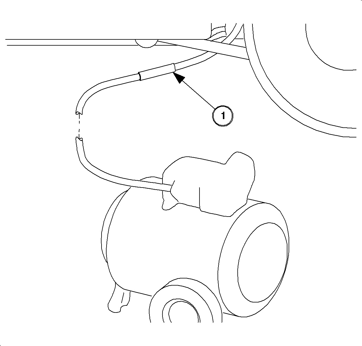
- Raise the vehicle on a hoist and install 5/16-inch male quick connect adapter (1), from the SA9127E-7 into the fuel feed line.
- Install the drain hose to the adapter and place the other end in a suitable container.
- Energize the fuel pump with the scan tool for one to two minutes. Refer to Fuel System Diagnosis . This will pump about 2 L (2 qt) of fuel and purge any debris in the fuel pump.
- Disconnect the fuel drain hose adapter at the fuel feed line and connect the fuel feed line to the fuel filter/regulator.
- Energize the fuel pump and check all of the connections for leaks.
- De-energize pump, lower the vehicle, and start the engine.
- Perform the Service Bay Diagnostic Test for the evaporative emission system using the scan tool. This test will verify the integrity of the vapor handling areas of the fuel system. Refer to Service Stall System (SSS) user guide.

Caution: Do not allow smoking or the use of open flames in the area where work on the fuel or EVAP system is taking place. Anytime work is being done on the fuel system, disconnect the negative battery cable, except for those tests where battery voltage is required.
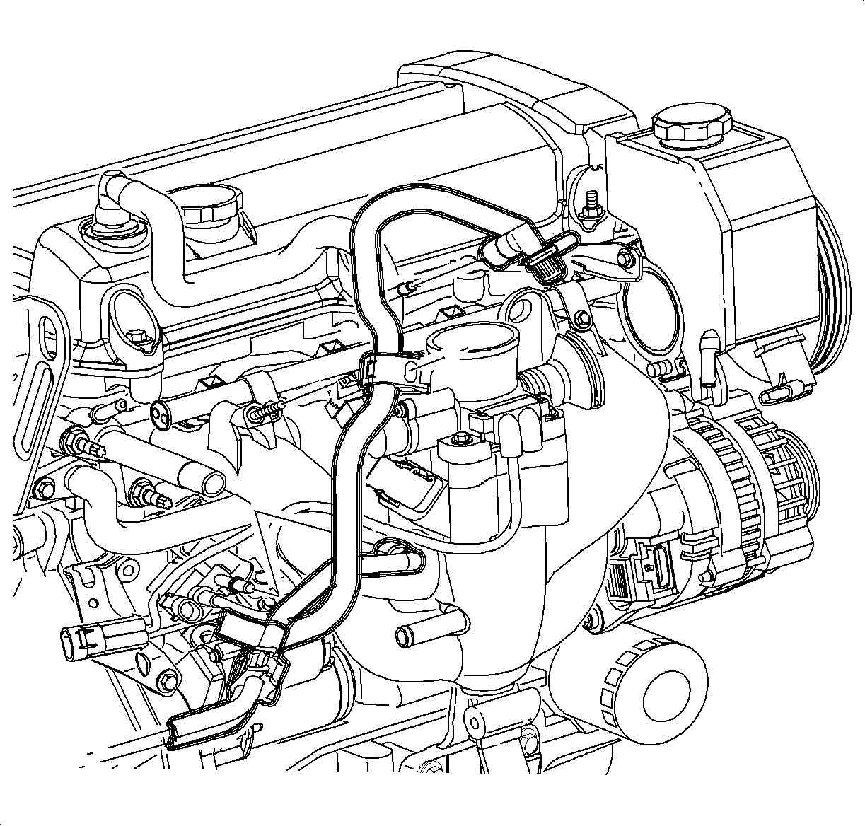
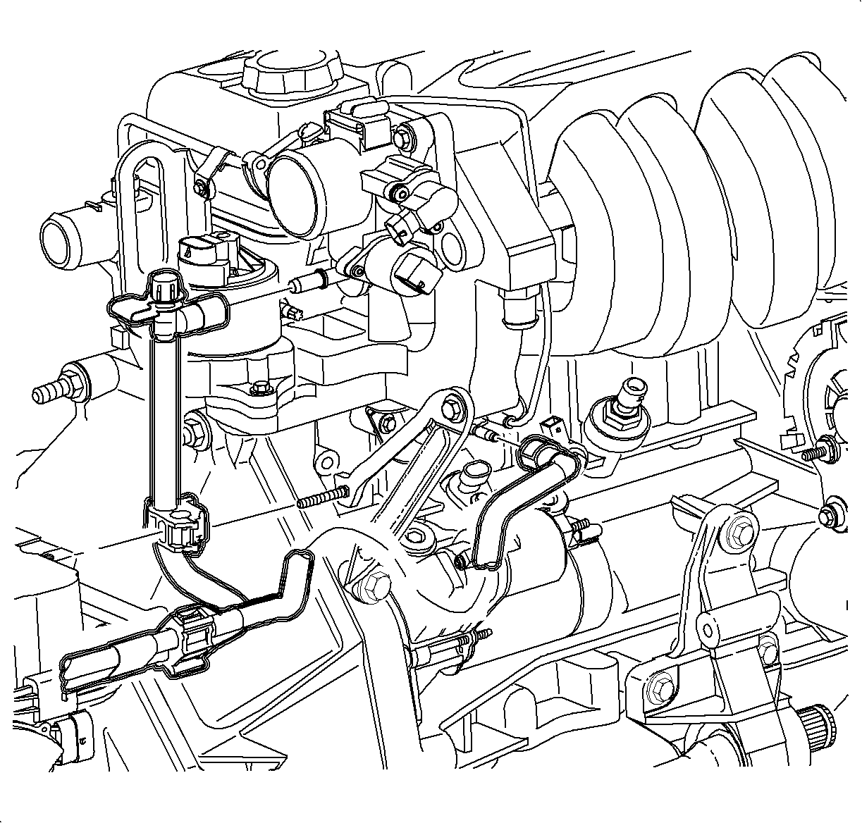
Notice: Replace plastic fuel line retainers whenever the fuel supply or return line is disconnected at the fuel rail. Install the new retainer into the female cavity of the connection. Care must be taken to ensure that the locking tab is centered in the window of the female cavity. Firmly press the female connection onto the male end until a click is heard, then pull back to confirm engagement. Pinched, kinked, or damaged fuel lines must be replaced.
Notice: Use the correct fastener in the correct location. Replacement fasteners must be the correct part number for that application. Fasteners requiring replacement or fasteners requiring the use of thread locking compound or sealant are identified in the service procedure. Do not use paints, lubricants, or corrosion inhibitors on fasteners or fastener joint surfaces unless specified. These coatings affect fastener torque and joint clamping force and may damage the fastener. Use the correct tightening sequence and specifications when installing fasteners in order to avoid damage to parts and systems.
Tighten
Tighten the battery terminal bolts to 17 N·m (13 lb ft).
Notice: Replace plastic fuel line retainers whenever the fuel supply or return line is disconnected at the fuel rail. Install the new retainer into the female cavity of the connection. Care must be taken to ensure that the locking tab is centered in the window of the female cavity. Firmly press the female connection onto the male end until a click is heard, then pull back to confirm engagement. Pinched, kinked, or damaged fuel lines must be replaced.
