Tools Required
| • | J 1859-A - Steering Wheel Puller |
| • | J 42578 - Steering Wheel Puller Legs |
Modify Cruise Control Module
- Depress the release tab on the adjuster and slide the adjuster off the cruise control module rod.
- Remove and discard the accelerator pedal bracket.
- Install the adjuster on the cruise module rod. The adjuster and rod are keyed to ensure proper orientation.
- Confirm that the adjuster is locked to the rod by pulling the adjuster rearward (the adjuster should slide forward but not rearward when properly installed).
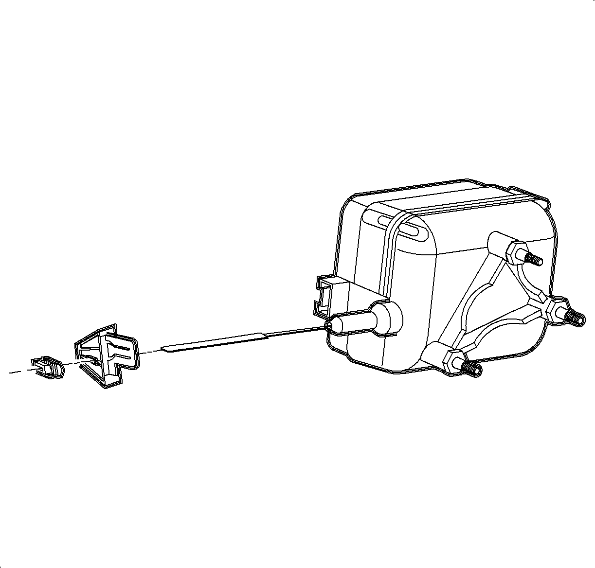
Important: The cruise control module must be modified as described in the following procedure before installing it on a RHD domestic vehicle.
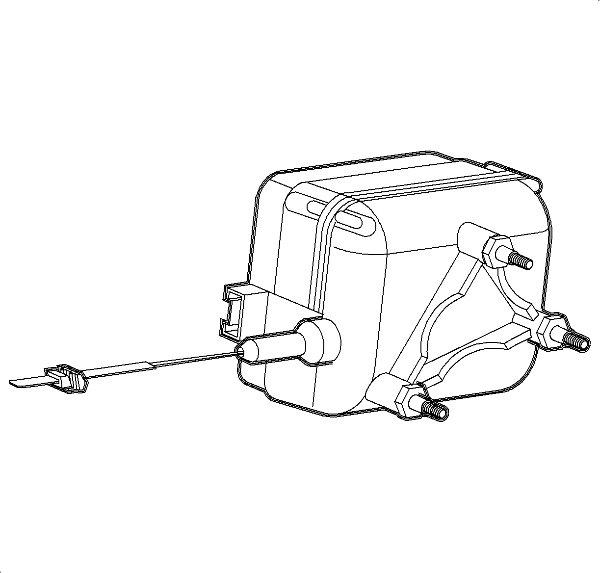
Install Cruise Control Module
- Locate the cruise control harness taped in the I/P harness, under the dash, near the center console air duct. (The cruise control harness has a black 6-pin connector.)
- Install the cruise control module on the steering column support bracket and tighten the nuts.
- Connect the cruise control rod bracket to the accelerator pedal. Snap the locating tab into the hole in the accelerator pedal.
- Connect the cruise control module harness connector. Push in the connector until a click is heard and pull back to confirm a positive engagement.
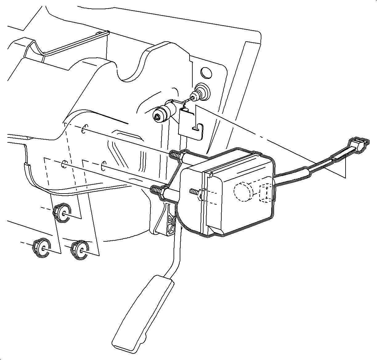
Notice: Refer to Fastener Notice in the Preface section.
Tighten
Tighten the cruise control module-to-steering column bracket to 6 N·m (53 lb in).
Adjust Cruise Control Module Rod
Refer to Cruise Control Module Rod Adjustment .
Remove Steering Wheel and Inflator Module
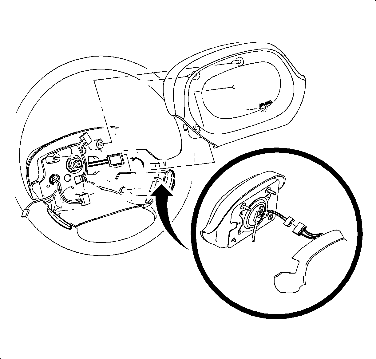
LHD shown; RHD similar.
- Disable the SIR system. Refer to Disabling the SIR System in SIR.
- Turn the steering wheel to the 3 o'clock position.
- Remove the inflator module by inserting a short flat blade screwdriver into the triangle shaped hole in the rear steering wheel shroud.
- Turn the screwdriver to release the spring fastener, while lifting up on the corner of the inflator module closest to that fastener.
- Repeat step 4 for the next fastener.
- Turn the steering wheel to 9 o'clock position.
- Repeat step 4 until all the spring fasteners are released.
- Disconnect the inflator module harness and the horn lead.
- Remove the inflator module.
- Disconnect the harness from the steering wheel.
- Remove the steering wheel attachment nut and discard.
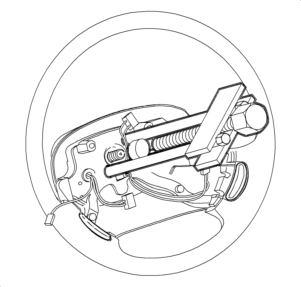
- Install J 1859-A by fitting J 42578 into the steering wheel puller holes.
- Install the puller bridge over the puller legs and finger, tighten the steering wheel puller nuts on the legs.
- Insert the center bolt through the bridge and align with the steering column shaft.
- Tighten the center bolt until the steering wheel is disengaged.
- Remove the steering wheel while feeding wiring through the wheel opening.
- Insert yellow tab or use a piece of tape to prevent coil assembly from rotating.
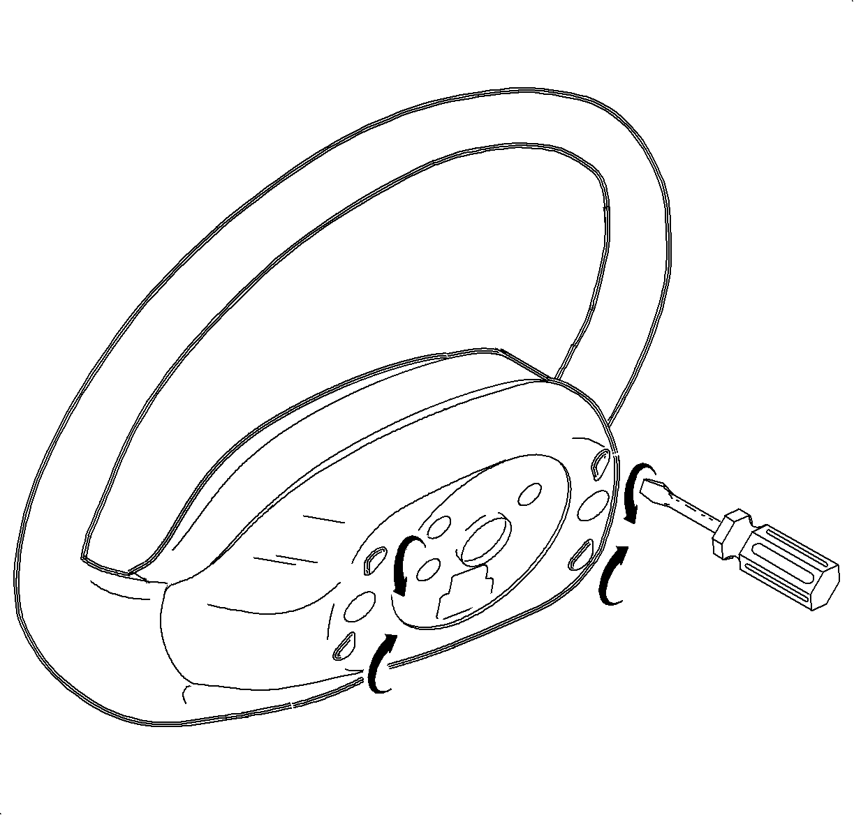
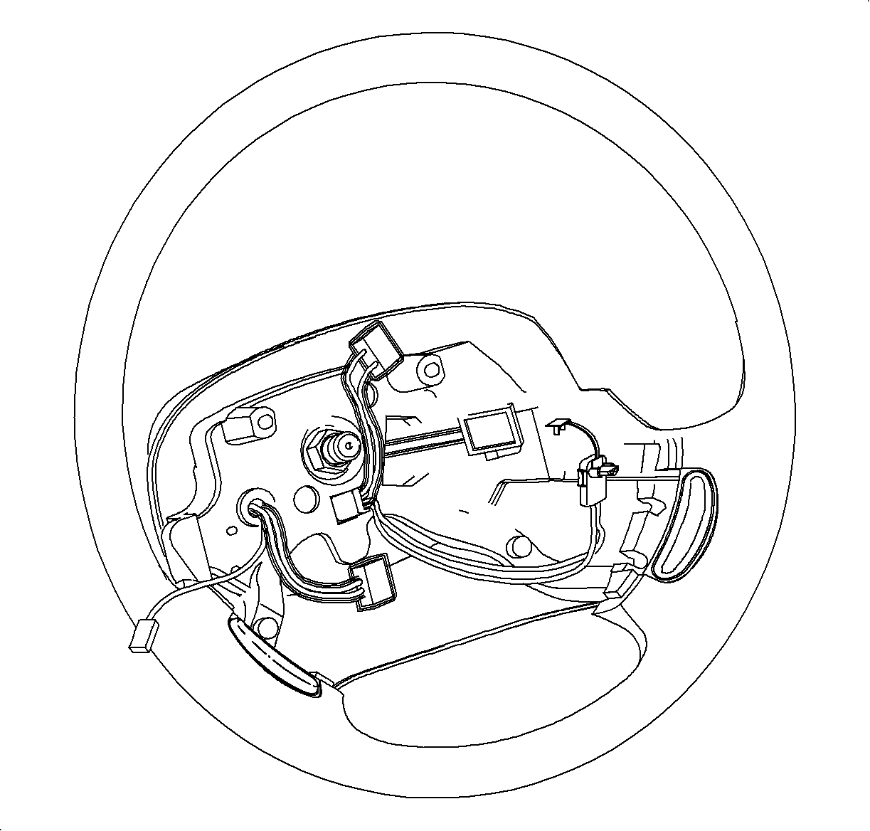
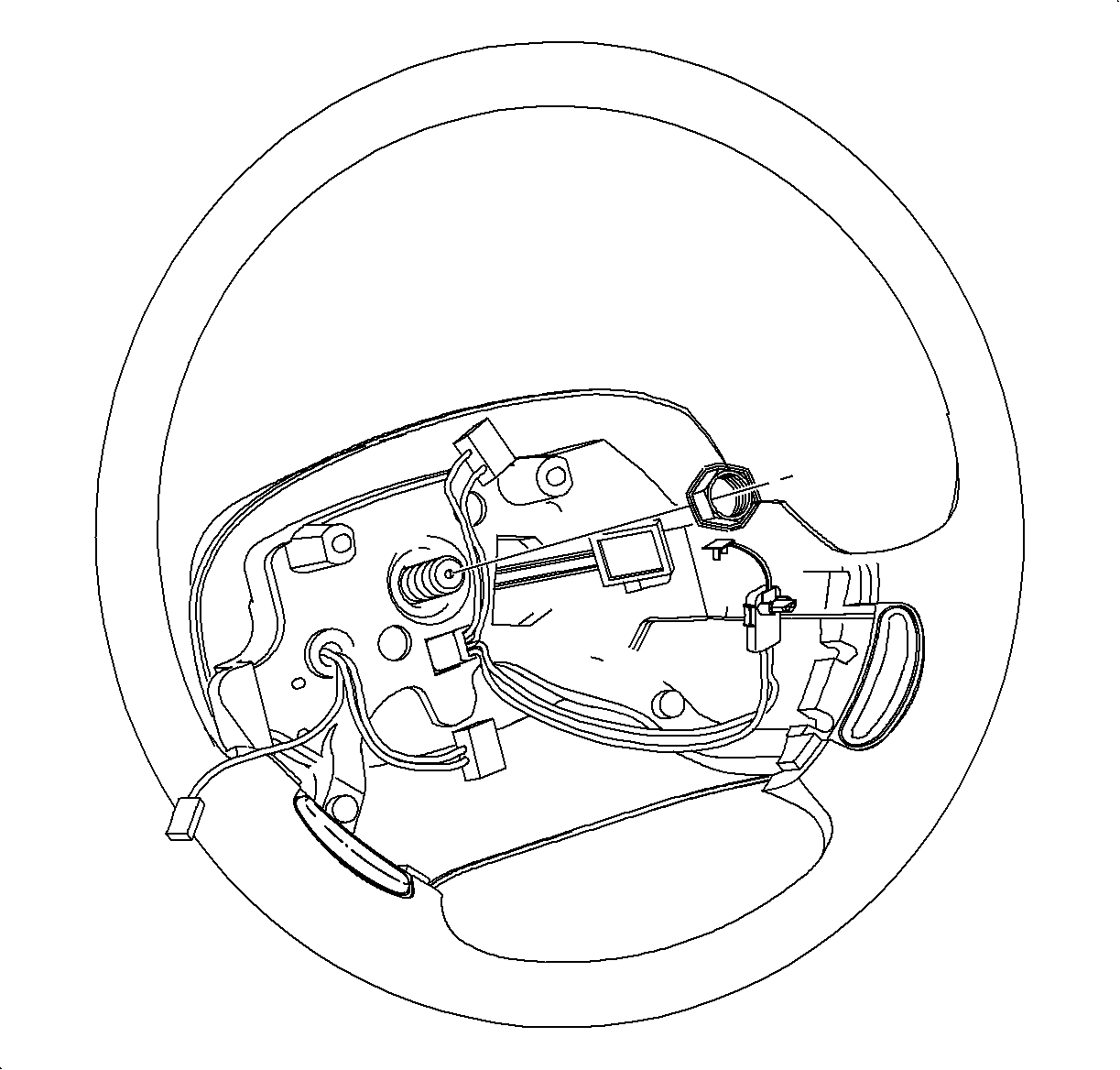
Notice: If roll connector is not properly oriented to steering column assembly, it will be damaged.
Important: If yellow tab is not available, use tape to prevent coil from rotating. If coil is rotated, refer to Inflatable Restraint Steering Wheel Module Coil Replacement in SIR.
Install New Steering Wheel and Inflator Module
- Remove the yellow tab or tape from the SIR coil assembly.
- Route wiring through the steering wheel and install the steering wheel onto the steering shaft noting orientation notch that locates steering wheel in the correct position.
- Install the new steering wheel attachment nut.
- Connect the cruise control switch connector and attach the harness to the wheel. Push in the connectors until a click is heard and pull back to confirm a positive engagement.
- Connect the inflator module wiring harness and install the harness integral connector lock device.
- Install the inflator module into the steering wheel. Be sure to seat all attachment points.
- Enable the SIR system. Refer to Enabling the SIR System in SIR.
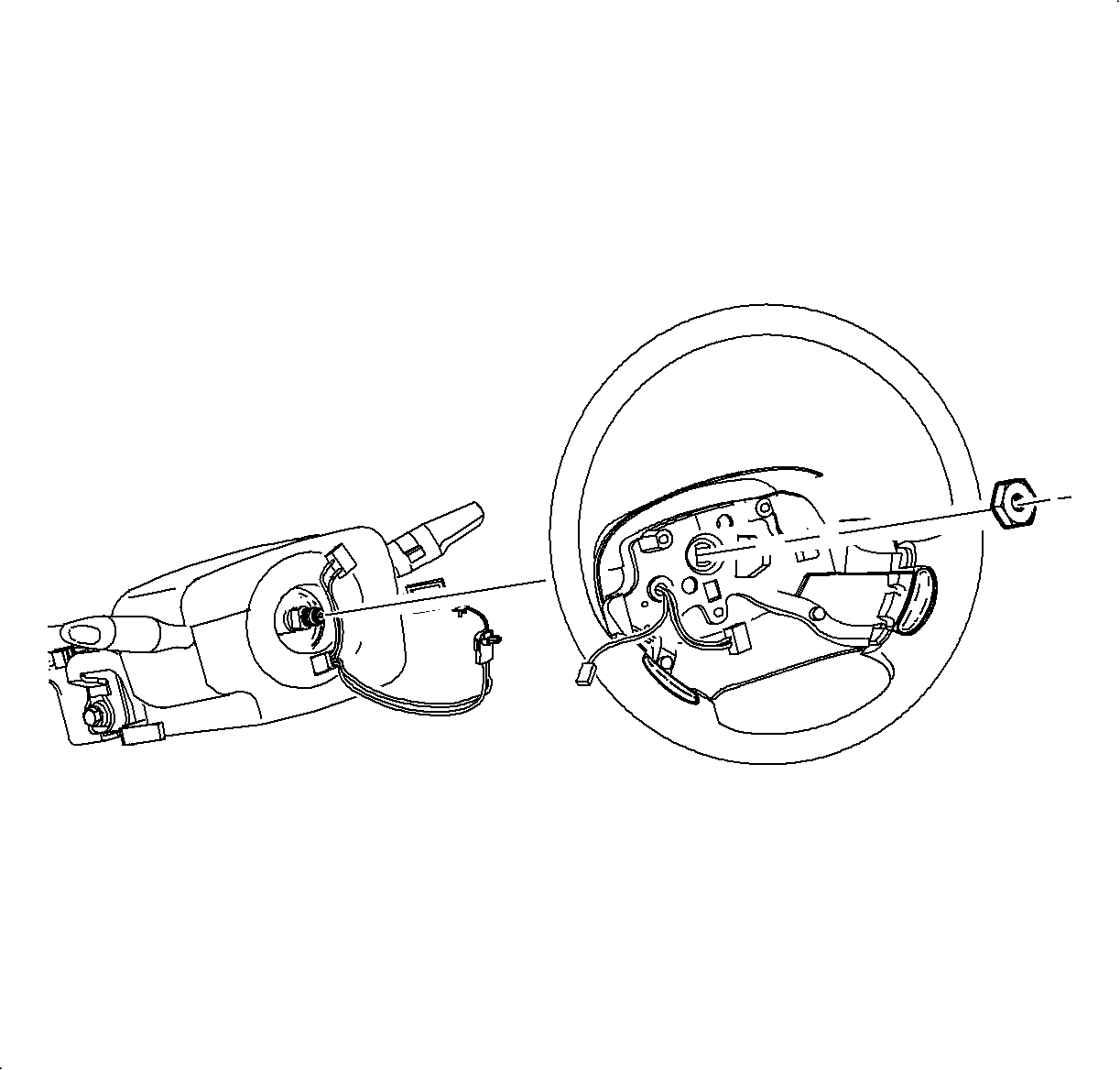
Important: A new steering wheel attachment nut must be used.
Tighten
Tighten the steering wheel attachment nut to 40 N·m (30 lb ft).


Reprogram PCM EEPROM Option To Enable Cruise Bit
Important: In order to set the CRUISE CONTROL option to YES, the entire PCM has to be reprogrammed. The latest software and calibrations can be selected for downloading if this is desired.
Change the CRUISE CONTROL option to YES by reprogramming the powertrain control module (PCM) using the Service Stall System (SSS). Refer to the Service Stall System (SSS) User Guide for reprogramming procedures.
System Performance Test
Complete the following procedures to confirm the installed cruise control system functions properly:
- Drive the vehicle at a speed of at least 40 km/h (25 mph) then enable the cruise control by turning the cruise ON/OFF switch to On.
- Cycle the brake pedal twice.
- Engage the cruise control by depressing the SET/COAST switch for a minimum period of 60 milliseconds (ms).
- Release foot from accelerator pedal. The vehicle should maintain cruise set speed.
- Disengage the cruise control by pressing the brake pedal. The vehicle should start to decelerate.
- Depress the RES/ACCEL switch for a minimum period of 60 ms. The vehicle should accelerate to the cruise set speed before the brake pedal was depressed.
- Press the RES/ACCEL switch for 60 ms to 700 ms. The vehicle should increase speed by 2 km/h (1 mph).
- Disable the cruise control by turning the cruise ON/OFF switch to Off. The vehicle should slow down until the accelerator pedal is depressed.
- If all of the above is operating correctly, then the cruise system is functioning correctly. Conclude the test by verifying no "active" DTCs are present in the PCM.
Important: The PCM must see at least one brake switch transition in the ignition cycle to allow cruise operation.
