2002 Saturn S-Series Vehicles (All Models)

| Subject: | ENGINE MOUNT BRACKET ASSEMBLY REPLACEMENT |
| Models: | 2002 SATURN S-SERIES VEHICLES (ALL MODELS) |
All Saturn Retailers and Authorized Service Providers
Saturn has decided that certain 2002 model year S-Series vehicles were produced with engine mount bracket assembly-to-engine motor mount fasteners that were not properly heat-treated. If these fasteners yield, the vehicle would exhibit objectionable engine vibration and noise.
To prevent the possibility of this condition occurring, Retailers will replace the engine mount bracket assembly.
Vehicles Involved
Only selected 2002 model year S-Series Saturn vehicles within the following VIN range will require this campaign:
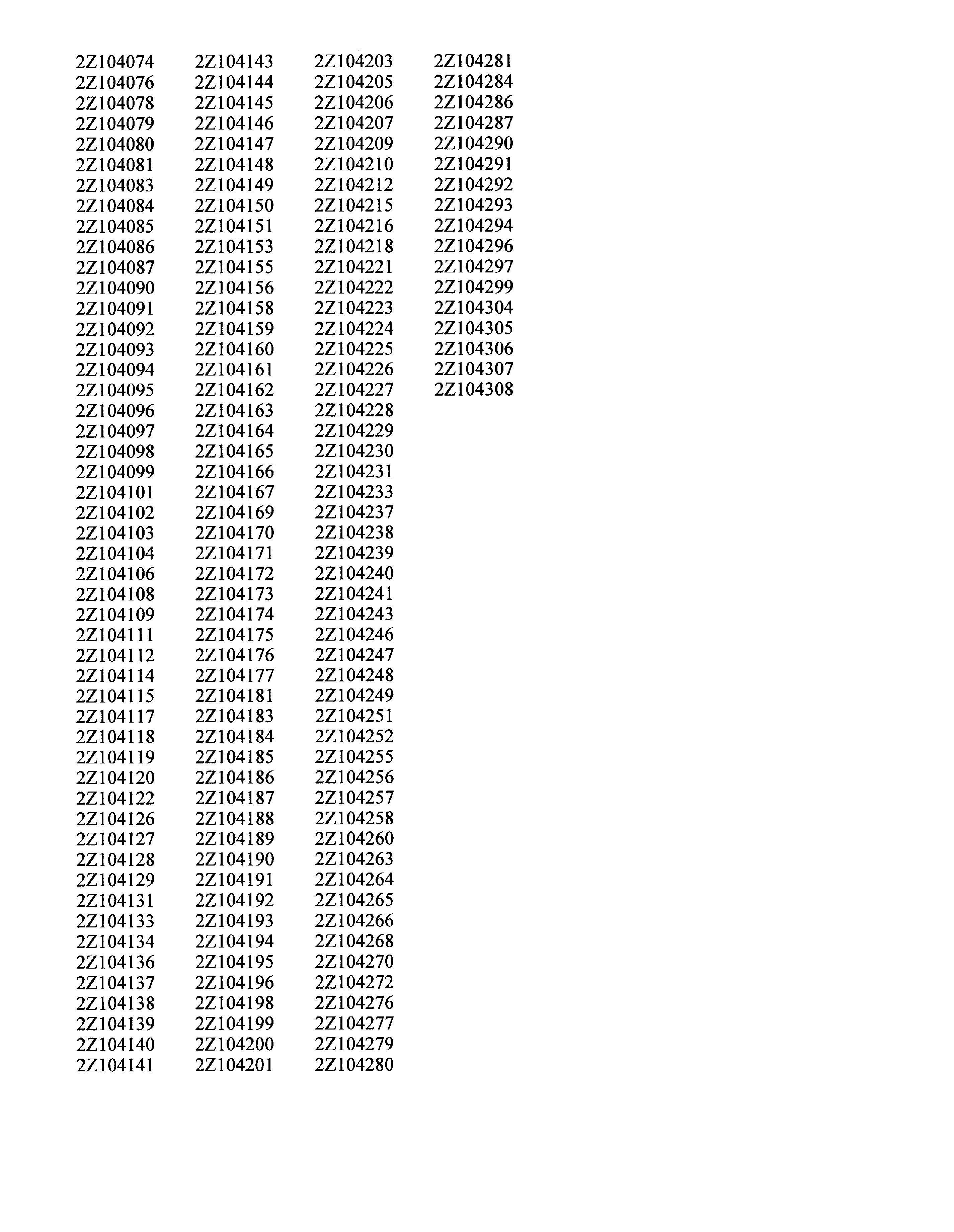
2Z104074 - 2Z104308
A VIN listing of the vehicles is included in this bulletin for your reference.
You must verify campaign involvement through your AS400 system. It is important to note that campaign claims will only be paid on involved vehicles.
Owner Notification
No owner vehicles are involved in this activity. Only vehicles in Retailer inventory are involved.
Facility VIN Listing
A list of vehicles assigned to you (Facility VIN Listing), which our records indicate were sold by or shipped to you, (or are located in close proximity to your facility) is enclosed.
This listing contains:
| • | Complete vehicle identification number (VIN); and |
| • | VINs of vehicles which according to Saturn records are in retail stock. |
The Facility VIN Listing is furnished to involved Retailers with the Product Campaign Bulletin.
Those Retailers not involved initially in this campaign will receive a message at the top of a blank Facility VIN Listing that states: NO VEHICLES ASSIGNED AT THIS TIME FOR CAMPAIGN 02-C-01.
Retailer Responsibility
All unsold vehicles in Retailers' possession and subject to this campaign must be held at the retail facility and repaired per the service procedure of this campaign bulletin before owners take possession of these vehicles.
In summary, whenever a vehicle subject to this campaign enters your vehicle inventory, or is in your retail facility for service in the future, please take the steps necessary to be sure the campaign correction has been made before selling or releasing the vehicle.
Transfer of Campaign Responsibility
Saturn vehicles that have been sold by you, which may be closer in proximity to another Saturn Retailer, may still appear on your Facility VIN Listing. If you determine that it is more desirable for a vehicle on your Facility VIN Listing to be serviced by another Saturn Retailer, campaign responsibility may be transferred by completing a Campaign Vehicle Action Report and submitting it to your Customer Assistance Manager (CAM) at the Saturn Customer Assistance Center.
A copy of the Campaign Vehicle Action Report is included for your reference. Additional copies can be ordered from Saturn Publications (1-800-828-2112, prompt 3, Item # S0397050). All changes to campaign responsibility will be reflected in your next Unfixed VIN Report.
All other changes in vehicle status (e.g., scrapped, stolen, etc.) are to be made in accordance with section 4.4.3 of the Retailer Service Reference Guide, "Notifying Saturn of Vehicle Status Change."
Parts Information
A pre-shipment of engine mount bracket assembly(s) and engine mount nuts required to perform this campaign has been automatically sent to involved Retailers from Saturn Service Parts Operations (SSPO). These initial parts shipments are to aid the Retailer in campaign preparation and will ensure minimal customer inconvenience.
Should additional parts be required, please order as needed.
Required Parts:
Part Number | Description | Quantity Required Per Vehicle |
|---|---|---|
21010960 | Engine Mount Bracket Assembly | 1 |
21006320 | Engine Mount Nut | 5 |
Disposition of Replaced Parts
Retailers will scrap all replaced parts in a manner that ensures that they cannot be reused, remanufactured, or otherwise entered into the stream of commerce in the future.
Service Procedure
- Raise the vehicle on a hoist.
- Remove the right front wheel and tire assembly.
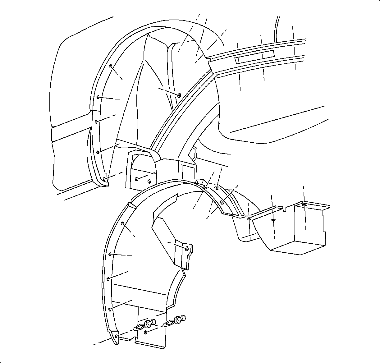
- Remove the right upper wheelhouse panel.
- Lower the vehicle enough to allow underhood access to the engine mount.
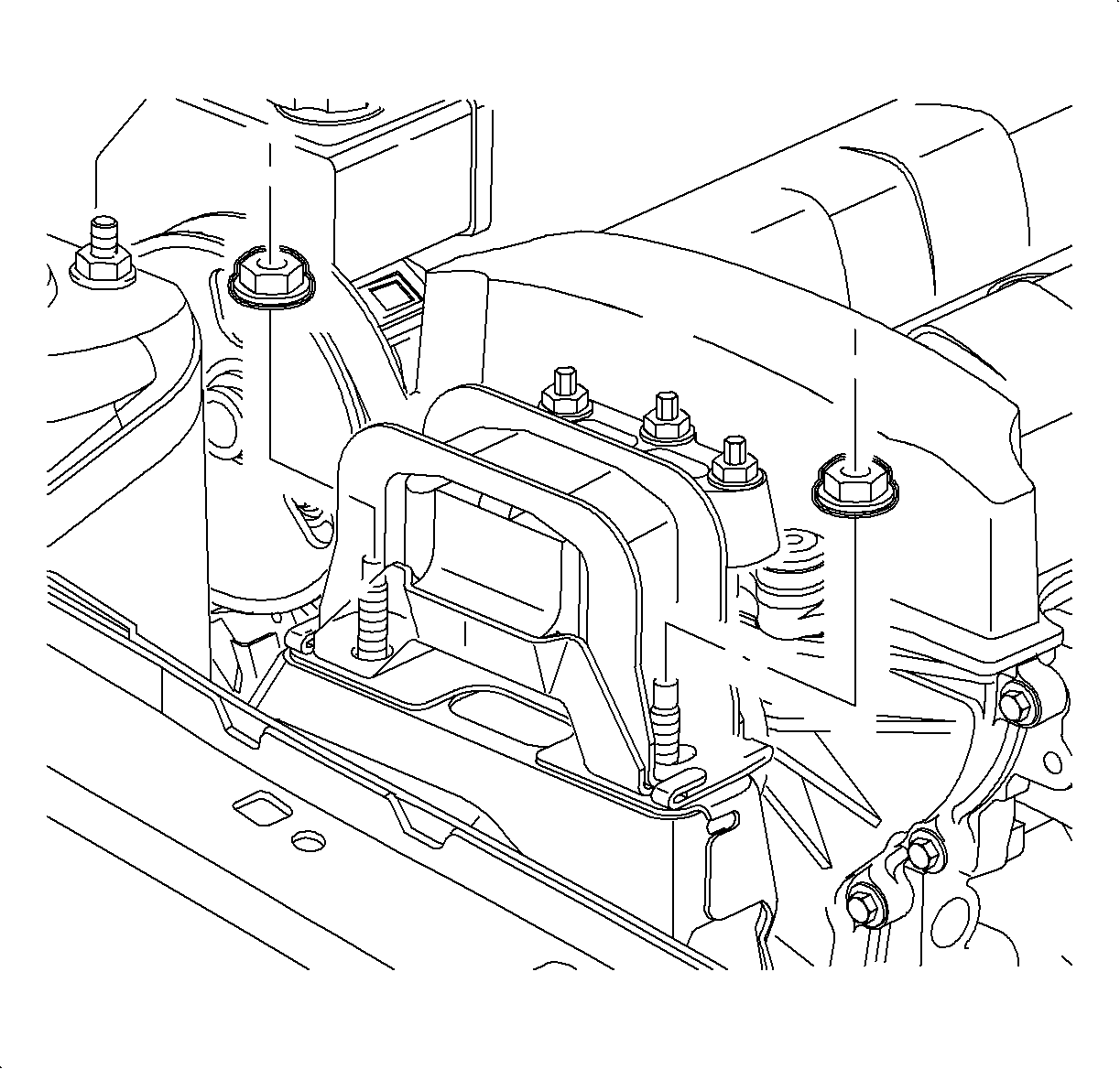
- Remove the two engine mount to midrail bracket nuts.
- Place a floor jack under the engine oil pan (use a block of wood between the oil plan and the jack). Raise the powertrain just enough to unload the mount to gain access to the fasteners. (The engine is raised enough when there is clearance between the mount and the midrail bracket.)
- Remove the three engine mount to front cover nuts and discard.
- Remove the engine mount.
- If the nut and the stud was removed as one unit, the old nut must be removed from the stud and discarded.
- Reinstall the stud(s).
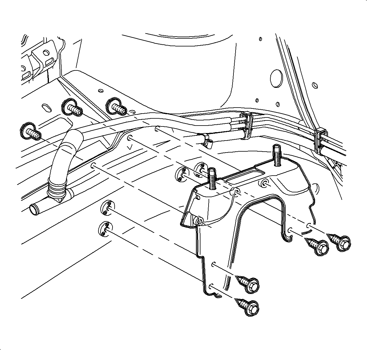
- From the engine side of the bracket, remove the four bracket to midrail fasteners.
- From the wheelhouse side of the bracket. remove the three bracket to the midrail fasteners, discard the old bracket.
- Obtain a new replacement engine mount bracket.
- Position the bracket to the midrail.
- Hand start all seven fasteners. (Four fasteners attached from the engine side of bracket, and three fasteners attach from wheelhouse side of bracket.)
- Tighten all fasteners, using a crowfoot wrench if necessary.
- Position the engine mount to the front cover and install new nuts.
- Completely lower the powertrain.
- Install the new engine mount to midrail bracket nuts.
- Raise the vehicle on a hoist.
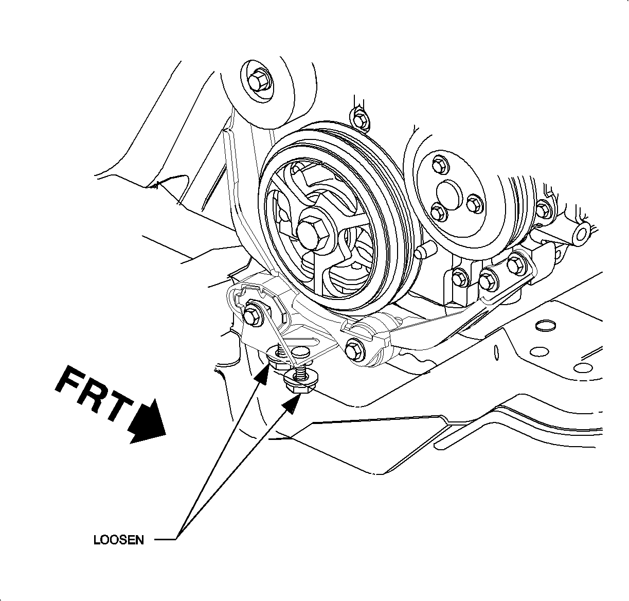
- Loosed the two engine stud bracket to frame fasteners to remove any fore/after preload from the engine strut.
- Tighten the engine strut bracket to the frame nuts.
- Install the upper wheelhouse panel.
- Position the right front wheel and tire assembly onto the hub.
- Install the wheel nuts and tighten in a crisscross pattern. Repeat tightening pattern to ensure tightening is correct.
- Lower the vehicle from the hoist.
- Affix the Campaign Completion Label on a clean and dry surface of the radiator core support, in an area clearly visible when the hood is raised. For more information, refer to Campaign Completion Label in this bulletin.
Caution: Verify that the vehicle is properly supported and squarely positioned on the hoist. To help avoid personal injury, provide additional support to the opposite end of the vehicle from which components will be removed.
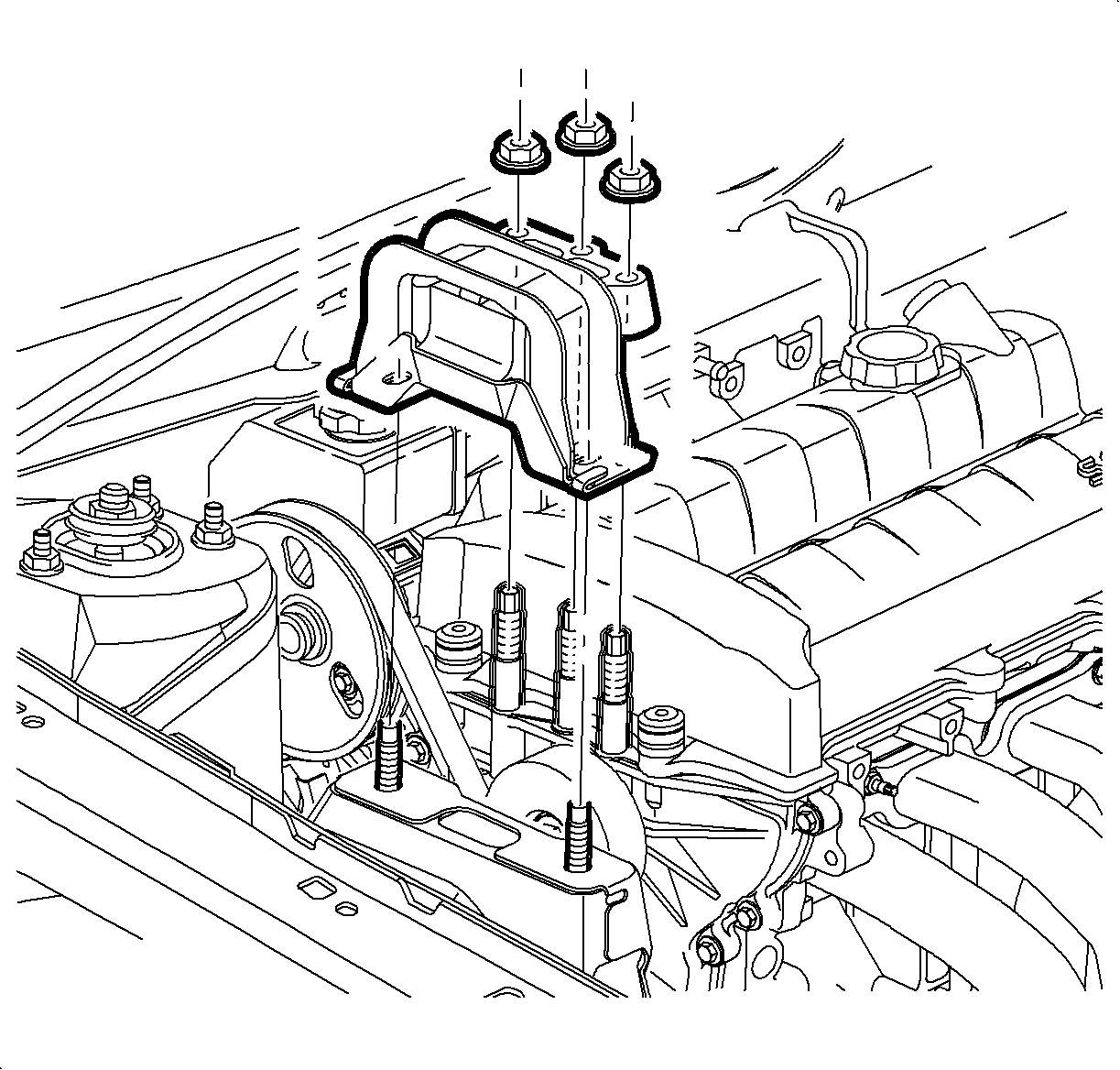
Notice: If the engine mount front cover stud turns or comes out during the nut removal, the stud must be fully install prior to installing the mount and/or nut. Damage to the front cover may occur if the stud is driven with the nut and does not sufficiently engage the front cover threads. Refer to step 9 for correct engine mount front cover stud(s) installation. If stud(s) did not come loose continue with motor mount bracket service procedure, step 11.
Important: Loctite 242® or equivalent is not required on studs during installation.
Tighten
Tighten the engine mount stud(s) to 10 N·m
(89 lb in)
Tighten
Tighten the midrail bracket fasteners to 32 N·m
(24 lb ft).

Important: Install the ground strap to the stud on the intake manifold side before installing the new nuts.
Tighten
Tighten the mount to front cover nuts to 50 N·m
(37 lb ft).

Notice: When lowering the powertrain, it will be necessary to guide the mount over the midrail bracket studs to prevent damage to the stud threads.
Tighten
Tighten the nuts to 50 N·m (37 lb ft).
Caution: Make sure the vehicle is properly supported and squarely positioned on the hoist. To help avoid personal injury, provide additional support to the opposite end of the vehicle that components will be removed from.
Tighten
Tighten the engine strut bracket to the frame nuts
to 50 N·m (37 lb ft).

Notice: Before installing the wheels, remove rust or corrosion from the wheel mounting surfaces and the brake rotors/ drums. Failure to do so can cause wheel nuts to loosen in service.
Tighten
Tighten the nuts to 140 N·m (103 lb ft).
Campaign Completion Label
Upon completion of the campaign, a Campaign Identification Label and a Clear Protective Cover should be affixed on a clean, dry surface of the radiator core support in an area clearly visible when the hood is raised. Each label provides a space to print in ink (or type) the campaign number (02C01) and the five (5) digit facility code of the Retailer performing the campaign service.
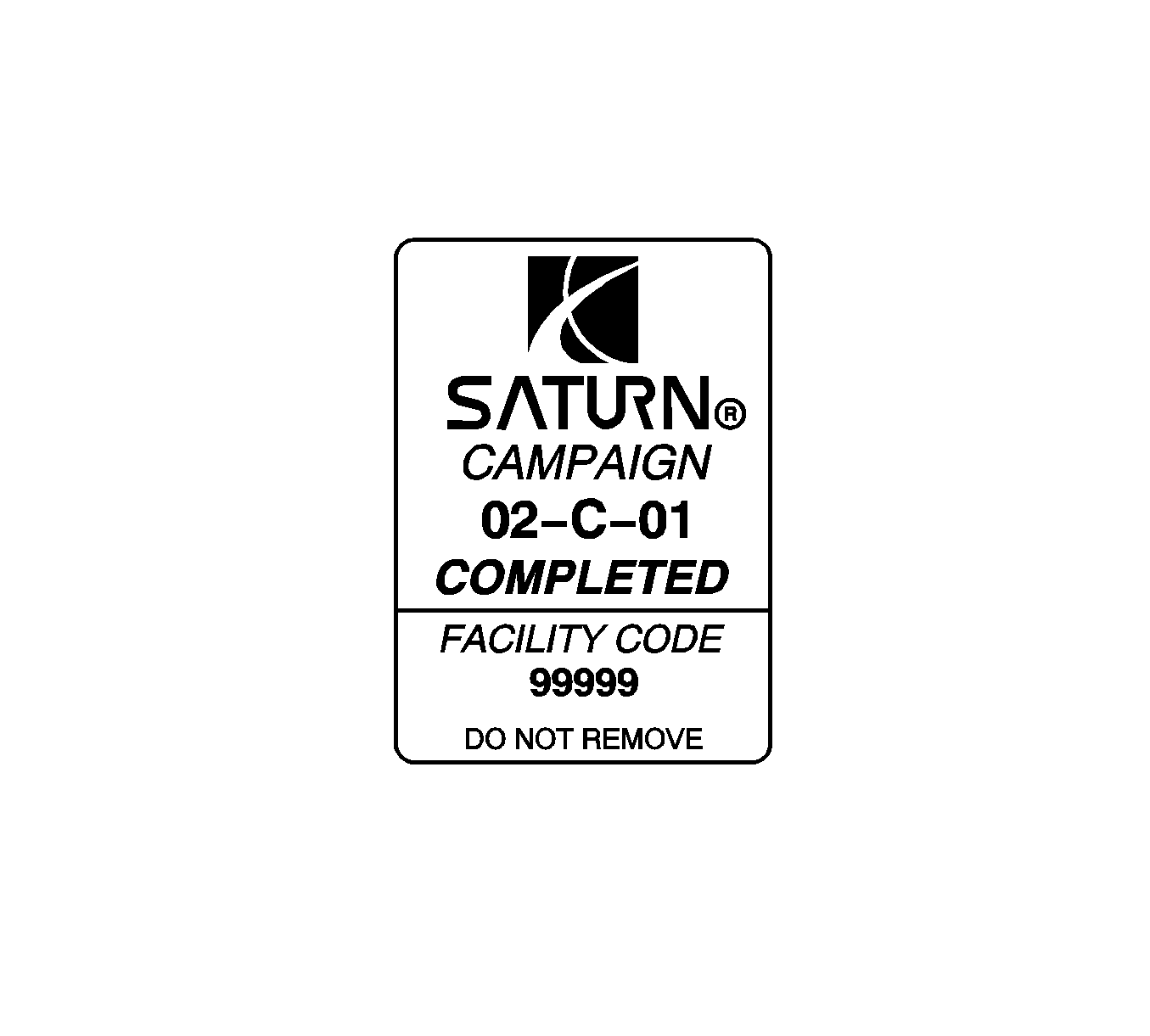
As a reminder, additional labels may be ordered from Saturn publications (1-800-828-2112, prompt 3, Item # S03 00013A for the Campaign Completion Label and Item # S03 00013B for the Clear Protective Cover ).
Credit
1. To receive credit for replacing the cooling fan control module, submit a claim with the information below:
Repair Information | Parts Allow. | Sale Type | Case Type | Labor Op | Labor Hours | Admin. Hours** | |
|---|---|---|---|---|---|---|---|
To Replace Engine Mount Bracket Assembly and Nuts (Includes reinstalling engine mount studs in front cover if necessary) | * | WC | VC | V0745 | 0.9 | 0.1 | |
2. Check your Saturn SERVICELINE.XL Claim Memorandum daily. Remember to code the claim as a WC sale type and VC case type. Contact your field representative if you need assistance.
3. All labor operations claimed in this bulletin must be submitted on individual (unrelated) CSO lines. Refer to the Customer Service Order Preparation Manual for details on Product Campaign Claim Submission.
* The parts allowance should be the sum total of the current SSPO Retailer net price plus 30% of all parts required for the repair.
** Campaign administrative allowance.
List of Involved Vehicles Within VIN Range
