| Table 1: | MAP Sensor Voltage Ignition ON Engine OFF |
Air Pump
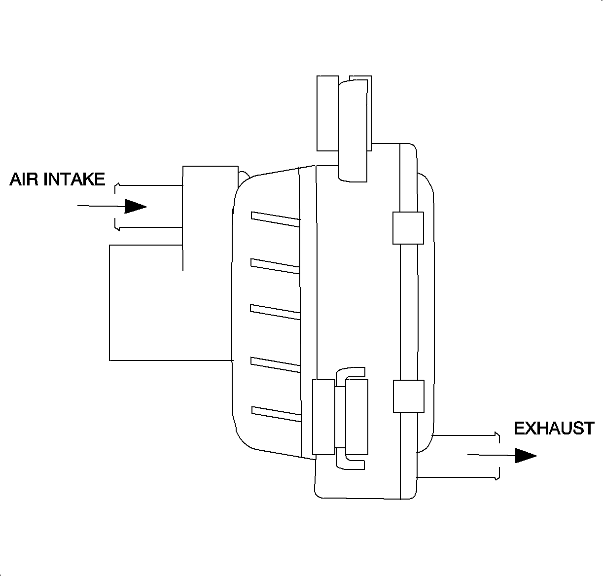
The air pump is located underhood near the right front headlamp. The purpose of the secondary air injection (AIR) system is to inject air into the exhaust manifold to quickly increase the temperature of the catalytic converters. The air pump creates the pressure needed to inject air into the exhaust manifold. The air pump is controlled by the powertrain control module (PCM) through the air pump relay in the underhood fuse block (UHFB).
Air Pump Solenoid
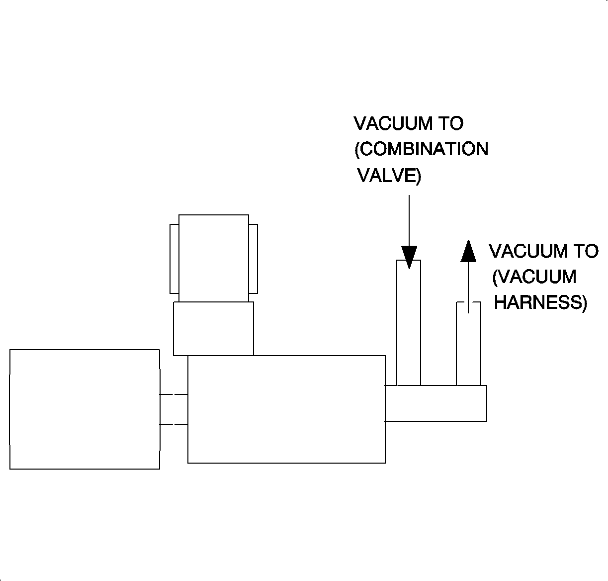
The air pump solenoid is located toward the front of the engine above the exhaust manifold. The air pump solenoid is part of the AIR system and is used to control manifold vacuum to the combination valve. When the air pump solenoid is energized, PCM supplies ground, manifold vacuum will pull the combination valve up and allow air from the air pump to flow into the exhaust manifold.
Combination Valve
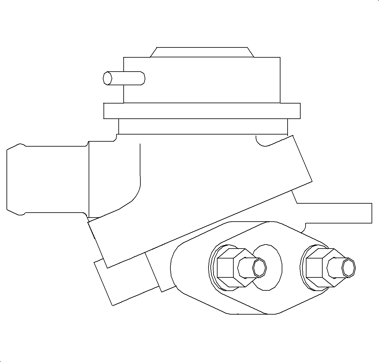
The combination valve is located toward the front of the engine above the exhaust manifold. The combination valve consists of 2 valves. The uppermost valve, a spring loaded diaphragm, is opened by vacuum which is regulated by the air pump solenoid. The lowermost valve, a reed valve, is opened by air pressure from the air pump. The reed valve helps prevent exhaust gas from recirculating back toward the pump. Air from the air pump flows through the diaphragm and reed valve to the exhaust manifold.
Crankshaft Position (CKP) Sensor
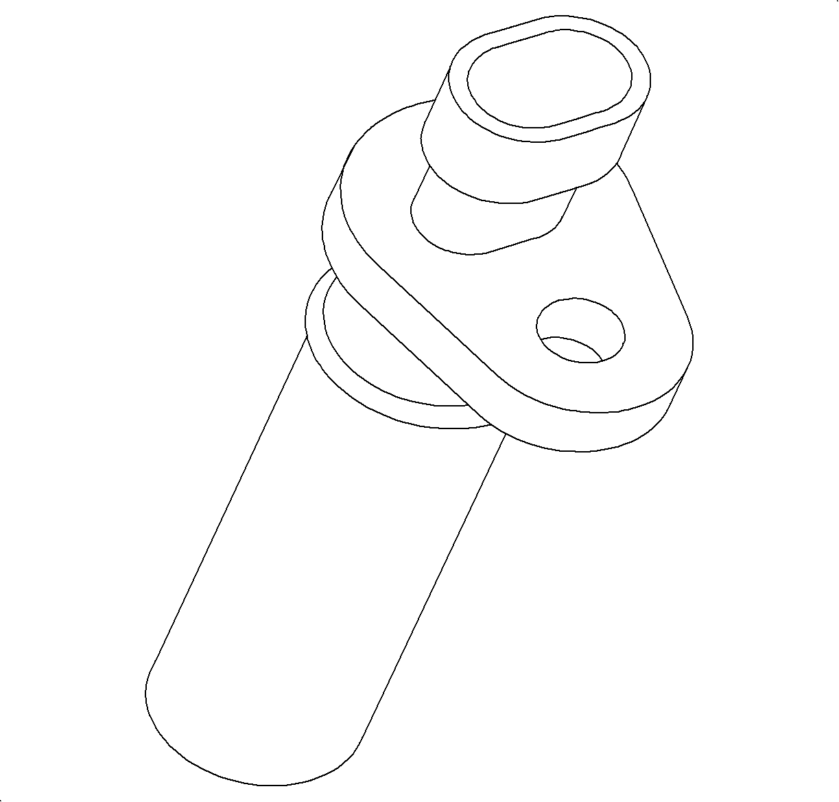
The CKP sensor is located in the back of the engine block near the starter motor. It produces an AC voltage of different amplitude, as high as 125 volts, and frequency depending on the velocity of the crankshaft. The crankshaft has 7 machined notches, 6 of which are spaced 60 degrees apart. The remaining notch is 10 degrees before the #4 cylinder top dead center (TDC) notch. The extra notch is used by the PCM to determine the position of the #4 cylinder and is necessary to synchronize engine position. The CKP sensor is used for fuel delivery, spark timing, misfire diagnostics and tachometer display.
TACHOMETER : The crankshaft position (CKP) sensor is used as an input to the PCM for tachometer information. The PCM uses voltage pulses from the CKP sensor to calculate RPM. The PCM sends an averaged tachometer message to the instrument panel (I/P) cluster over the Class II link every 100 ms. The PCM averages the tachometer information to ensure smooth tachometer fluctuations.UPSHIFT TELLTALE : On manual transaxle vehicles, the PCM optimizes fuel economy by informing the driver when the transaxle should be shifted to the next higher gear. The PCM bases its determination on engine speed and engine load. When the PCM determines that the driver should shift to the next higher gear, it sends a message to the I/P cluster over the class 2 link to turn ON the Upshift telltale.
EI Module and Coil Pack
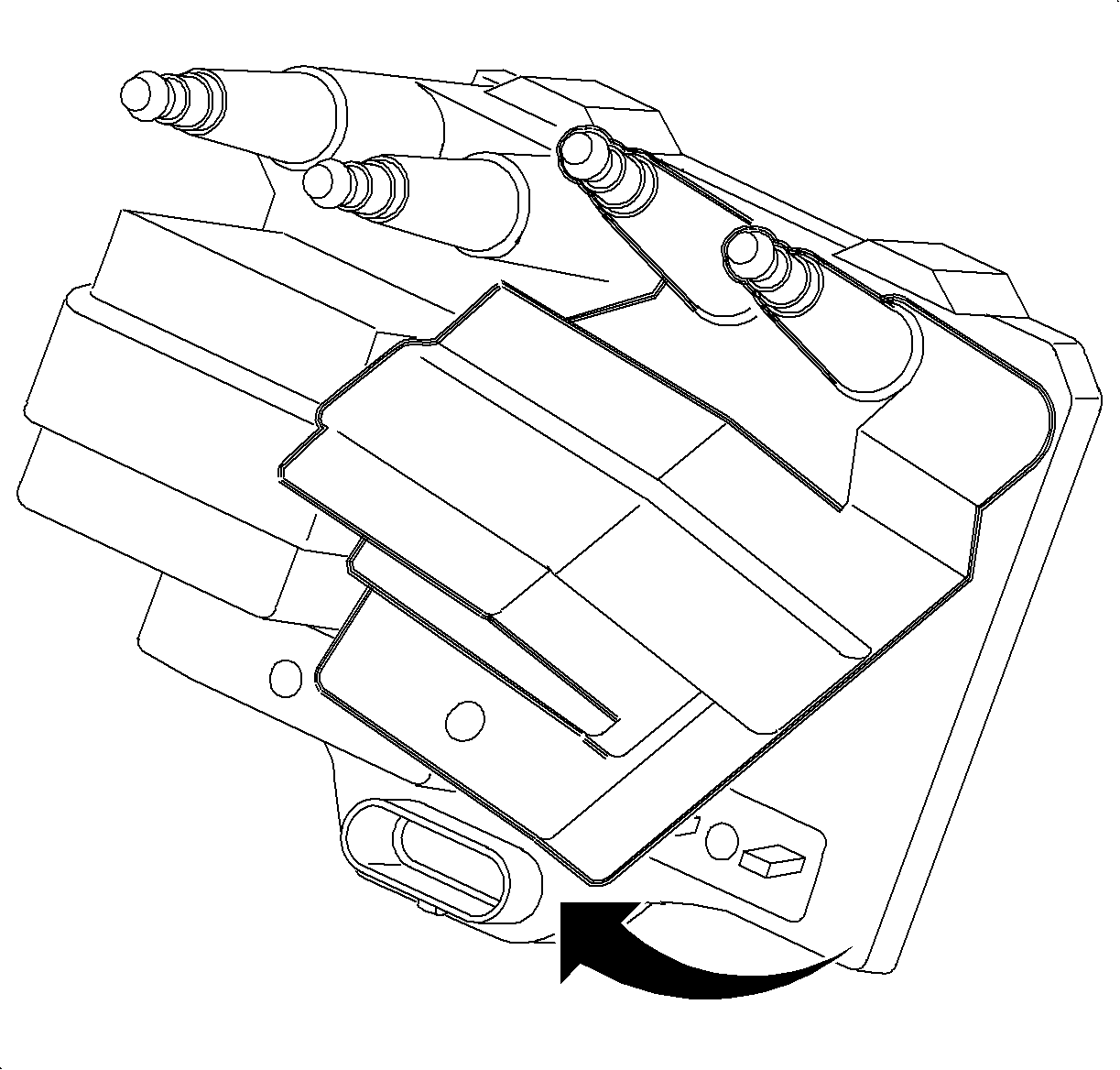
The electronic ignition (EI) module and coil pack is located on the transaxle housing attached to the spark plug wires. The electronic ignition (EI) module charges and discharges the coils based on PCM control. The PCM uses a high control signal of near 5 volts to charge up the coil and a low control signal of near 0 volts to discharge the coil. If the coil is charged and the control signal is low, the coil will fire through its secondary towers. The PCM controls spark timing and dwell (spark On-time) under all engine running conditions.
The EI module also has the ability to determine when #4 cylinder has fired on compression by the use of compression sense ignition circuitry. This eliminates the need for a camshaft position sensor. Refer to Fuel Controls Description .
Engine Coolant Temperature (ECT) Sensor
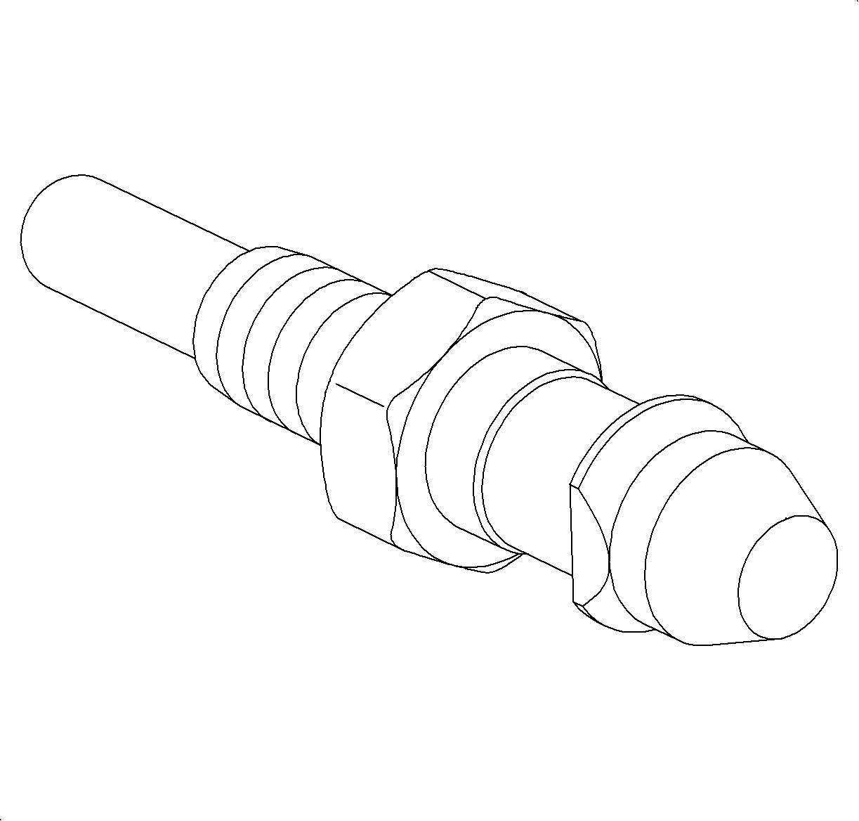
The ECT sensor is located in a coolant passage in the side of the cylinder head near the upper radiator hose. The ECT sensor is a two wire thermistor type sensor that varies resistance according to changes in engine coolant temperature. The PCM supplies a five volt reference through a resistor to the sensor, which is connected to ground. When the sensor is cold it has high resistance, high signal voltage at PCM. As the sensor temperature increases, its resistance decreases, lower signal voltage at PCM. The PCM uses the signal voltage to determine engine coolant temperature.
The ECT sensor is used by the PCM for fuel control, calculation of temperature of air/fuel mixture at the intake valve in conjunction with the IAT sensor temperature, Coolant Temp telltale illumination, coolant temperature gage position and cooling fan relay operation. The PCM also uses the ECT sensor for ignition timing, exhaust gas recirculation (EGR) operation, evaporative emission (EVAP) purge solenoid control, idle speed control and oil life monitoring.
COOLING FAN MOTOR CONTROL: The PCM controls the cooling fan motor by grounding the cooling fan relay. When the relay coil circuit is grounded, the switch side of the relay closes allowing current to flow to the cooling fan motor.The PCM operates the cooling fan relay based on the reading from the ECT sensor. Under normal operating conditions, the cooling fan operates whenever the ECT is greater than 105.5°C (226°F) or the A/C relay is commanded ON below 113 km/h (70 mph). The cooling fan will turn OFF when the temperature drops below 100°C (212°F). If the engine is turned OFF and the ECT is above 107°C (225°F), the cooling fan can run up to 4 minutes or until the ECT drops below 107°C (225°F). If a low/high ECT circuit fault (DTC P0117 or P0118) is set, the PCM will command the cooling fan relay ON to protect the engine and transaxle until the condition is corrected.
Degrees (°C) | Degrees (°F) | Sensor Resistance (ohms) |
|---|---|---|
-40 | -40 | 77k-109k |
-29 | -20 | 39k-53k |
-18 | 0 | 21k-27k |
-7 | 20 | 11k-15k |
4 | 40 | 6.6k-8.4k |
16 | 60 | 3.9k-4.5k |
27 | 80 | 2.4k-2.7k |
38 | 100 | 1.5k-1.7k |
49 | 120 | 0.98k-1.1k |
60 | 140 | 650-730 |
72 | 160 | 430-480 |
83 | 180 | 302-334 |
94 | 200 | 215-235 |
105 | 220 | 159-172 |
120 | 248 | 104-113 |
140 | 284 | 63-68 |
COOLANT TEMP TELLTALE: The Coolant Temp telltale is used to alert the driver that the engine may be in an overheated condition. The PCM controls the Coolant Temp telltale by sending a message to the I/P cluster over the class 2 link. The PCM will send the message when the ECT sensor reading is above 118°C (244°F). If this condition exists, the PCM will set DTC P0217. If a high temp/low voltage fault exists in the ECT sensor circuit, the signal is considered invalid and the Coolant Temp telltale will not be illuminated. The malfunction indicator lamp (MIL) and cooling fan relay will be commanded ON, however.
Engine Oil Pressure (EOP) Switch
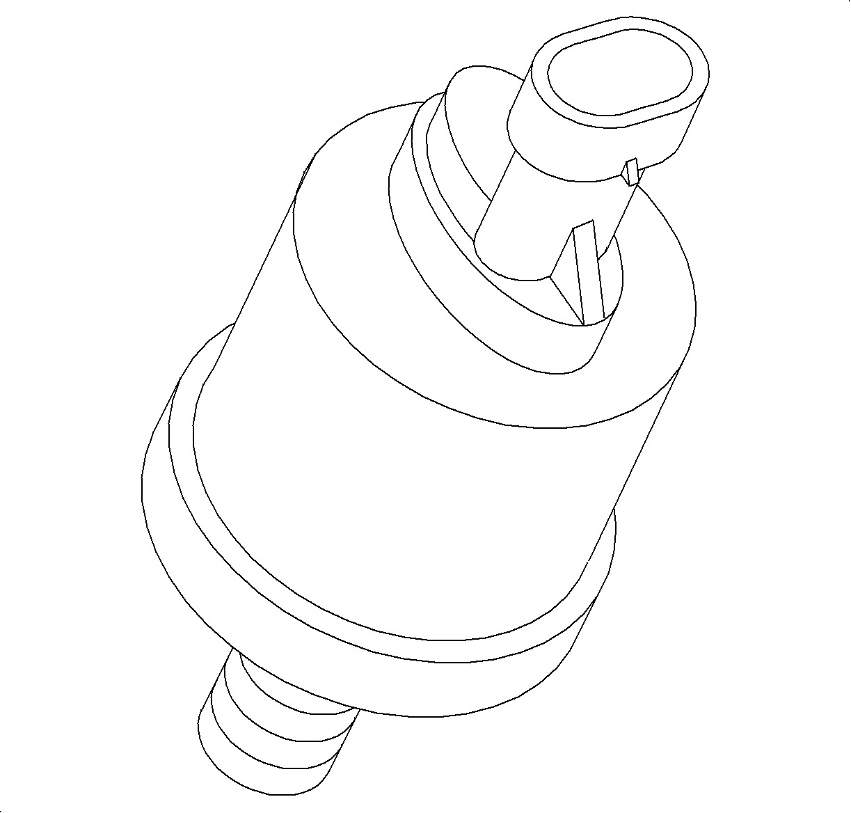
The engine oil pressure (EOP) switch is located in the back of the engine block near the starter motor. The EOP switch is a normally closed switch that opens when engine oil pressure exceeds 3.6 +/- 2.2 psi. The PCM supplies ignition voltage through a resistor to the EOP switch. With ignition ON, engine OFF, the PCM EOP input will be low, near 0 volts, switch closed. When the engine is started and engine oil pressure exceeds 3.6 +/- 2.2 psi, the switch opens and the PCM EOP input goes high, ignition voltage.
OIL PRESSURE TELLTALE: The PCM sends a message to the I/P cluster over the class 2 link to turn ON the Oil Pressure telltale whenever the ignition is ON and the EOP input at the PCM is low.Evaporative Emission (EVAP) Canister
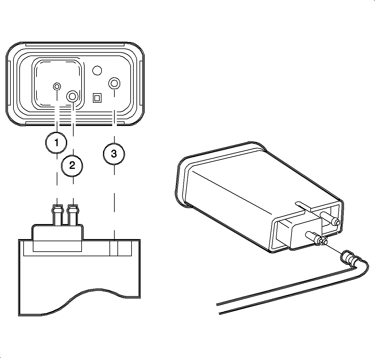
The EVAP canister stores unburned fuel vapors and prevents them from escaping into the atmosphere. The EVAP canister contains a carbon filter bed which holds fuel vapors until they are purged into the intake manifold through the EVAP purge solenoid. Fresh air normally flows though the EVAP vent solenoid to the EVAP canister, then into the fuel tank to keep the fuel tank at atmospheric pressure.
Evaporative Emission (EVAP) Purge Solenoid
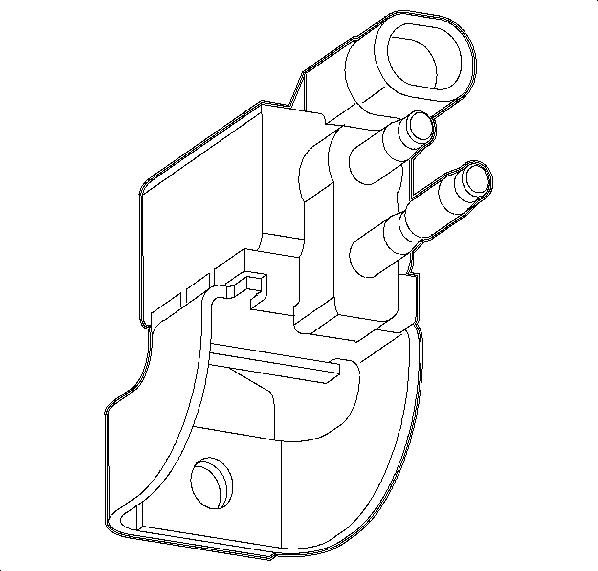
The EVAP purge solenoid is located to the back of the engine block, below the intake manifold just above the starter motor. The EVAP purge solenoid controls the flow of fuel vapors from the EVAP canister to the intake manifold. The EVAP purge solenoid is commanded ON (PWM) when the EVAP system is in purge mode. Fuel vapors can be purged anytime the PCM is in Closed Loop and the vehicle is not decelerating. The PCM controls the EVAP purge solenoid by grounding the solenoid circuit.
Evaporative Emission (EVAP) Service Port
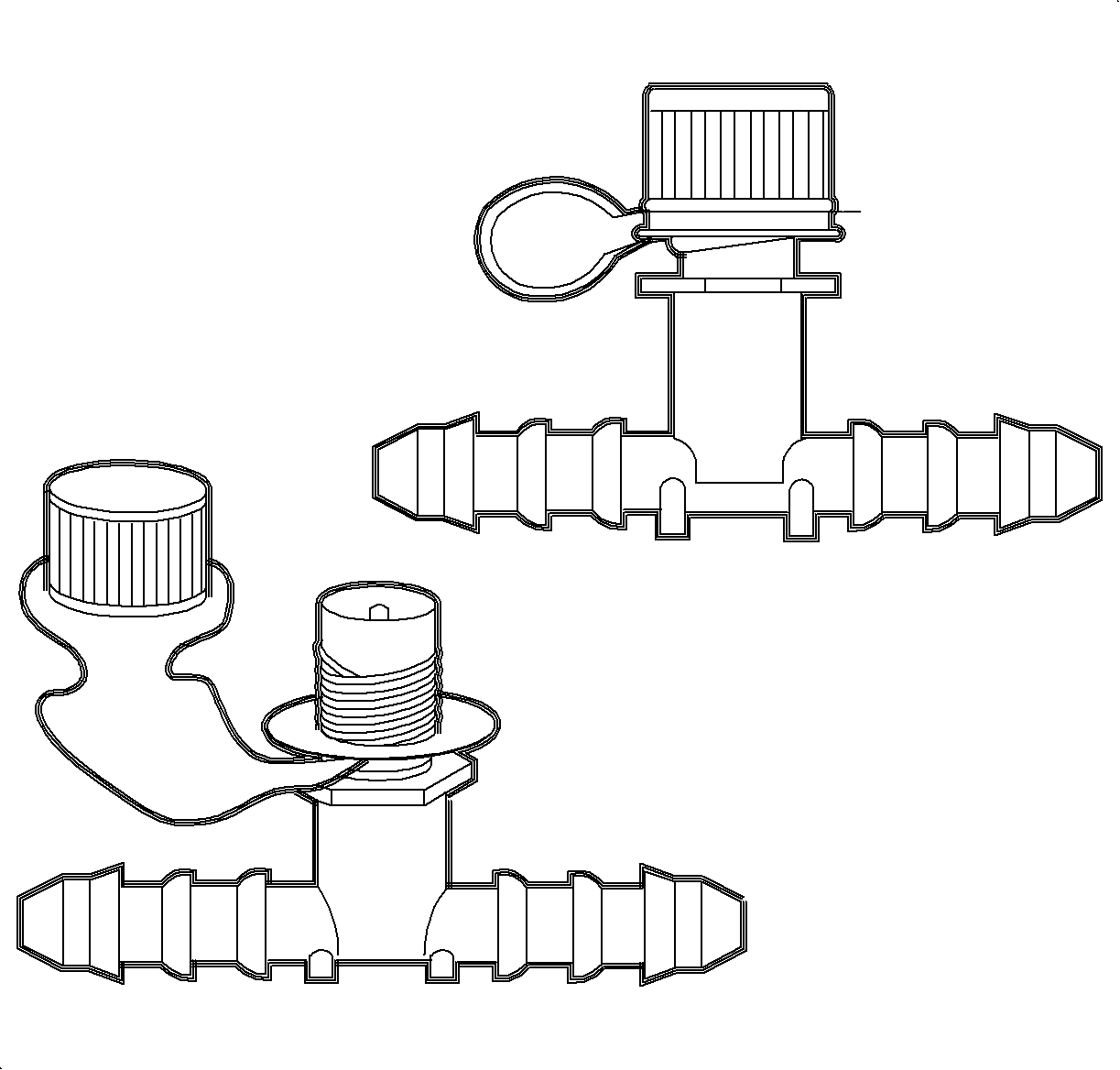
The EVAP service port is located in the EVAP purge line underneath the vehicle left side floor pan. The service port is identified by a green colored cap. The port is between the EVAP purge solenoid and the EVAP canister. The port contains a shrader valve to allow the connection of the service tool kit, Enhanced EVAP Pressure Purge Diagnostic Cart J 41413 .
Evaporative Emission (EVAP) Vent Solenoid
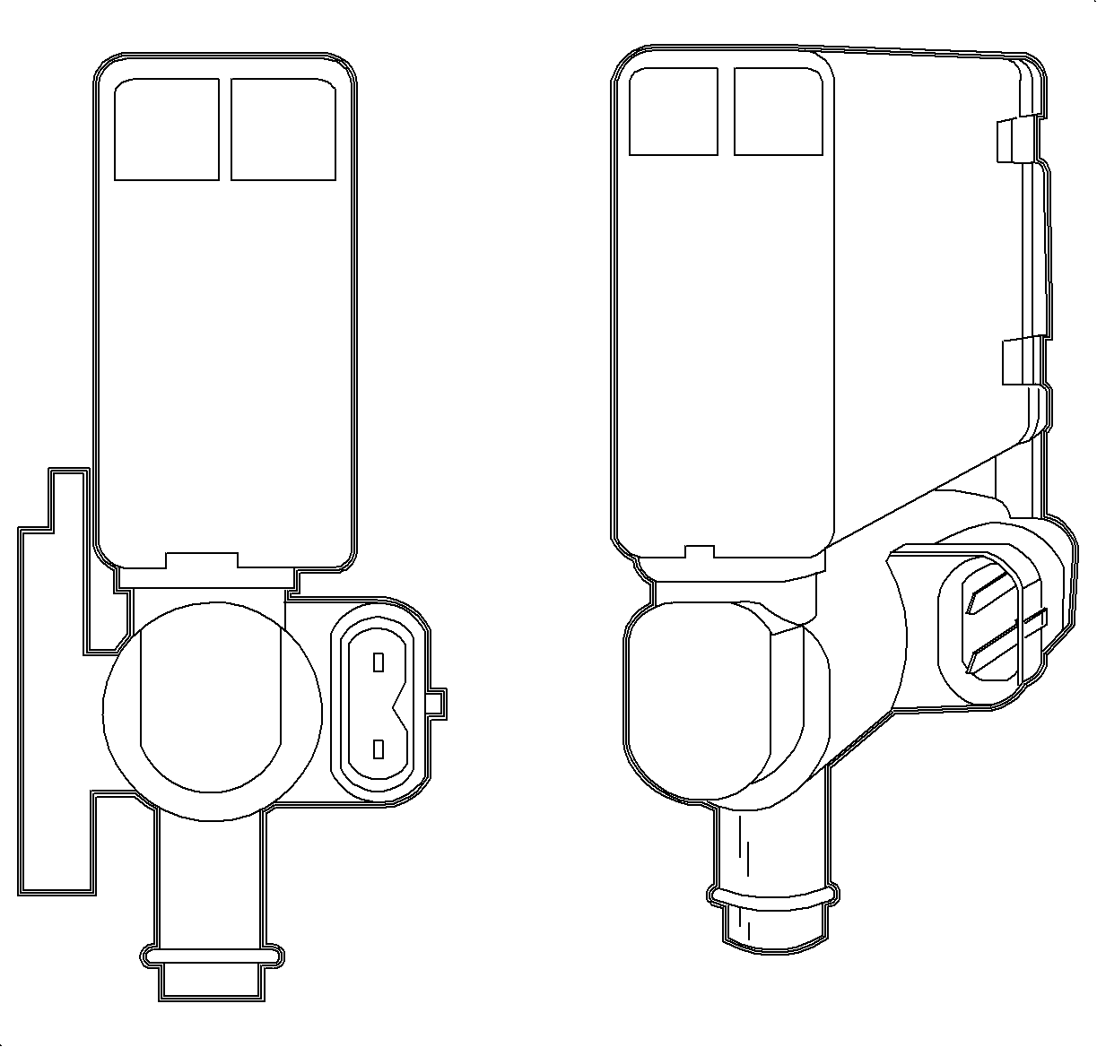
The EVAP vent solenoid is located toward the top of the fuel filler neck tube. The sole function of the EVAP vent solenoid is for EVAP leak diagnostics. Outside air flows around the normally open valve , except during portions of the EVAP diagnostics, through the EVAP canister to the fuel tank. This allows the fuel tank to be at atmospheric pressure (101 kPa). The PCM controls the EVAP vent solenoid by grounding the solenoid circuit, closes valve.
Exhaust Gas Recirculation (EGR) Valve
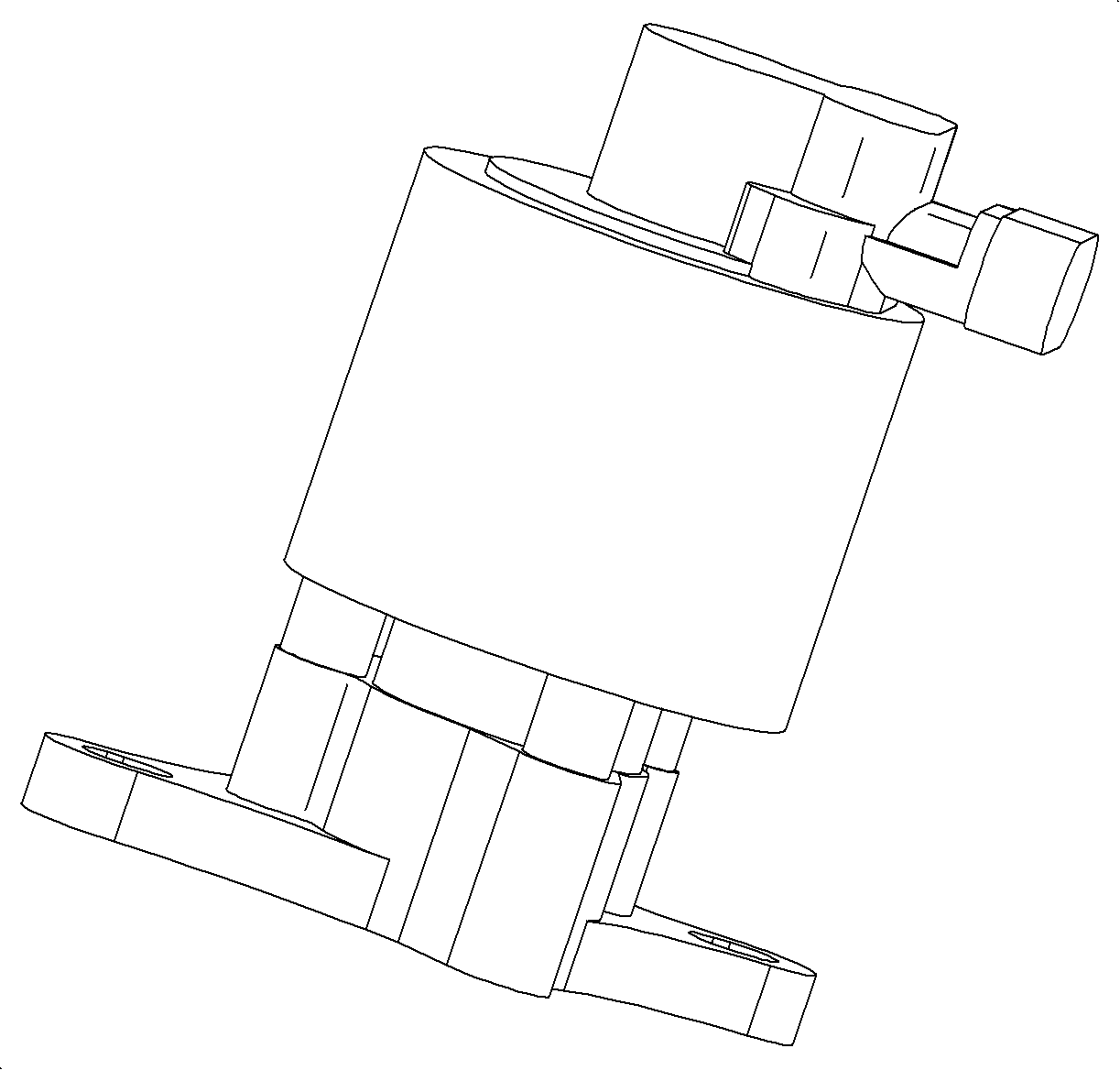
The EGR valve is located on the side of the cylinder head near the upper radiator hose. Exhaust gas is introduced into the intake manifold via the EGR valve to be mixed with the air/fuel during combustion. EGR is used to cool combustion chamber temperatures which reduce oxides of nitrogen (NOx), an emission gas related to combustion temperatures. The EGR valve consists of a pintle valve that moves by the use of an internal solenoid and an internal position sensor (potentiometer) used to determine pintle valve position. The PCM controls the solenoid by supplying ignition voltage whenever exhaust gas needs to be recirculated into the intake manifold. The position sensor works exactly like that of a throttle position (TP) sensor. The PCM supplies the sensor 5 volts and a ground. A sweep arm is used to give the signal voltage level at a certain position of the valve.
Fuel Injector
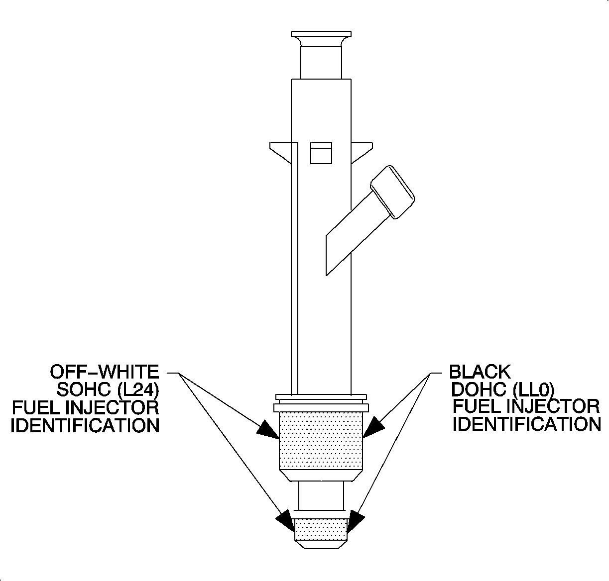
The fuel injection system on both SOHC and DOHC engines utilize sequential fuel injection. The PCM independently controls each fuel injector. The PCM grounds each fuel injector circuit for a certain length of time based on engine operating parameters. The fuel control system is designed to maintain a 14.7:1 air/fuel ratio under all engine running conditions except power enrichment, heavy acceleration/heavy engine load, and deceleration modes. The PCM can turn fuel injectors OFF during deceleration, misfire diagnostics and traction control.
Fuel Pump
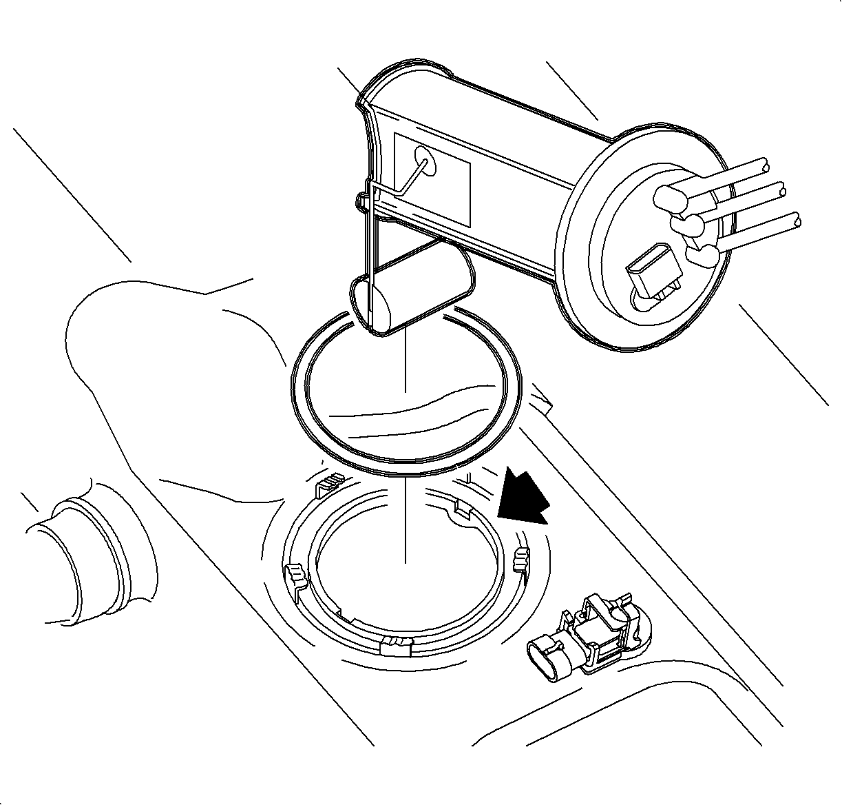
The fuel pump motor, located inside the fuel tank, supplies fuel pressure to the fuel injectors. The PCM controls the fuel pump motor by controlling the fuel pump relay. The fuel pump motor is supplied constant ignition voltage whenever the fuel pump relay is turned ON. The PCM turns ON the fuel pump relay whenever the engine is running or for 2 seconds when the ignition is turned ON and the engine is not running.
Fuel Level Sensor

The fuel tank level sensor is part of the fuel tank sender assembly inside the fuel tank. This sensor varies resistance according to changes in the level of fuel in the fuel tank. The PCM supplies ignition voltage reference to the sensor, which is connected to ground. A resistor circuit in the PCM slightly lowers the voltage supplied to the sensor to approximately 0.2 volts less than ignition voltage. When the level in the fuel tank is high, the sensor resistance is low, low voltage on signal line. As the fuel level decreases, the sensor resistance increases, voltage increases on the signal line. The PCM uses the signal voltage to determine fuel tank level. The fuel level sensor is also used to determine fuel level necessary for EVAP diagnostics.
FUEL GAGE: The PCM sends fuel tank level messages over the class 2 link to the BCM. The BCM averages the information over time then sends the averaged fuel level to the I/P cluster over the link. The I/P cluster then positions the fuel gage.LOW FUEL TELLTALE : If the fuel level is low, the PCM will send a message to the BCM, which sends a message to the I/P cluster over the class 2 link to turn ON the Low Fuel telltale. The Low Fuel Telltale will turn ON when approximately 1.2 gallons (1-1.5 gallon range) of usable fuel remains in the tank.
Fuel Tank Pressure Sensor
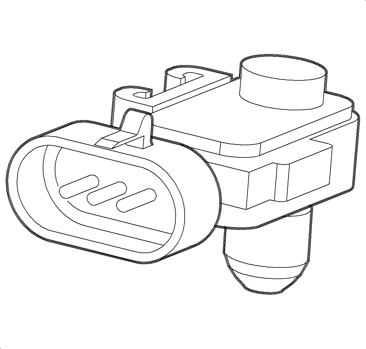
The fuel tank pressure sensor is located on top of the fuel tank. The function of the fuel tank pressure sensor is solely for EVAP leak diagnostics. The fuel tank pressure sensor is a transducer that varies resistance according to changes in fuel tank pressure. The fuel tank pressure sensor works inverse to a MAP sensor. The PCM measures the signal voltage from the fuel tank pressure sensor, which is a reduced value of the PCM 5 volt reference. The signal voltage reads high when the pressure in the fuel tank is low (vacuum) and decreases as the pressure in the tank increases.
Generator
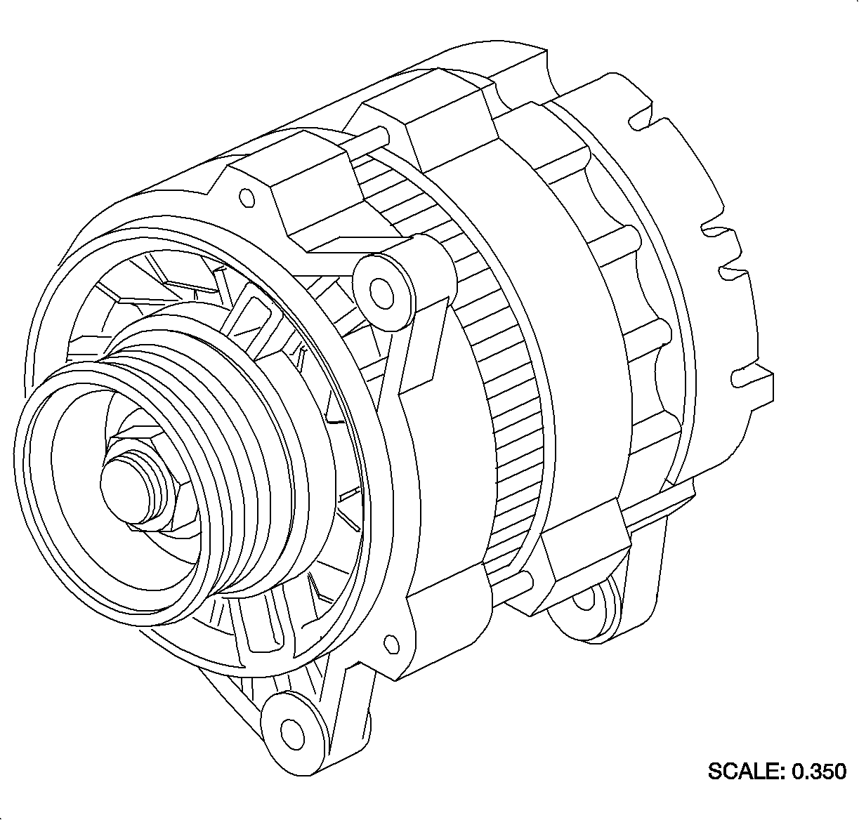
The PCM controls generator charging by supplying 5 volts on the generator L-terminal circuit whenever the ignition is turned ON or the engine is running. This control voltage is necessary for the generator to charge once the generator begins to spin. With the ignition ON, engine OFF, the generator will ground the generator L-terminal circuit through a resistor. When the engine is started and the generator begins to charge, the generator will open the circuit, still using the 5 volt control voltage, signaling to the PCM that the generator is charging.
CHARGE TELLTALE: If the voltage at the PCM generator L-terminal is low or if the circuit is grounded when the engine is running, the PCM will send a message to the I/P cluster over the class 2 link to turn ON the Charge telltale.Heated Oxygen Sensor 2 (HO2S-2)
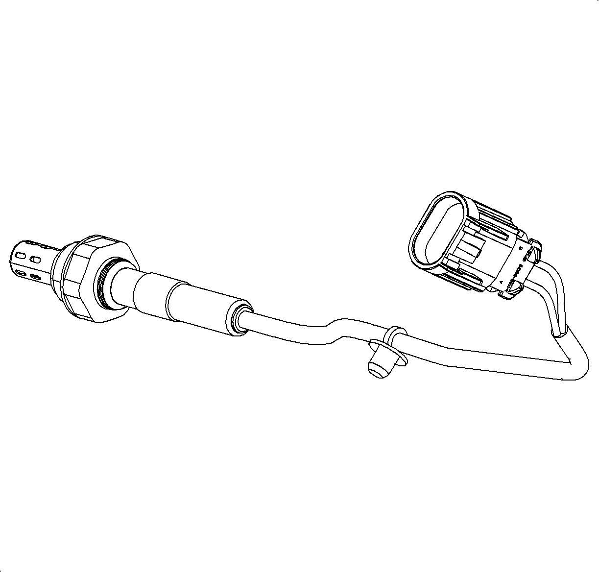
The HO2S-2 is located behind the main catalytic converter. The function of the sensor is to monitor the efficiency of the catalytic converter. The sensor is a four-wire sensor; two are used for the heater and the other 2 are used for the oxygen sensor signal. The HO2S-2 is an electrical source that responds to oxygen content in the catalytic converter. When the sensor reaches approximately 316°C (600°F), it produces a voltage based on the difference in oxygen between the atmosphere and exhaust gas. The PCM sends a bias voltage (391-491 mV) on the signal line which can be read by the scan tool when the sensor is cold. When the HO2S-2 is cold, it produces no voltage and has extremely high internal resistance. However, when the sensor heats up, it produces voltage that overrides the bias voltage. This voltage is read by the PCM to determine the efficiency of the catalytic converter. Under normal conditions, low sensor voltage means high oxygen content/lean air-fuel mixture and vice versa. Normal sensor readings at steady cruise with a properly functioning catalytic converter will be steady around 500-800 mV.
Idle Air Control (IAC) Valve
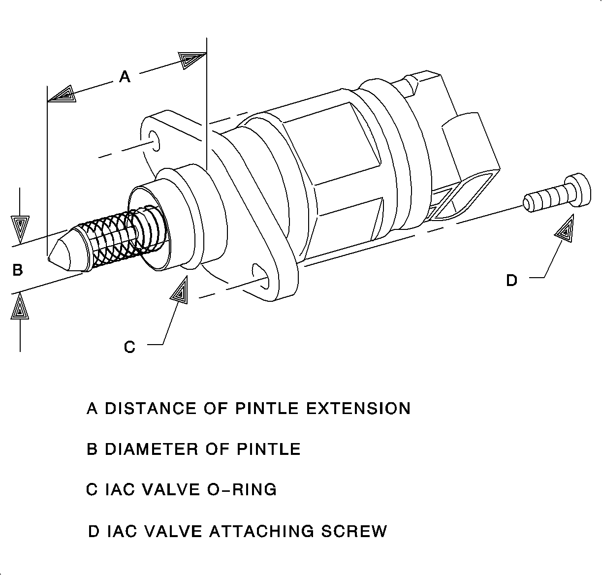
The IAC valve is located in the throttle body on both SOHC and DOHC engines. The idle speed is controlled by the PCM using the IAC valve. The IAC valve consists of a two-coil stepper motor that moves a pintle valve in and out from the seat controlling the amount air bypassing the throttle plate. The PCM controls the IAC valve by supplying ignition voltage or ground to any of the four circuits of coil A or coil B. When one circuit of a coil is supplied ignition voltage the other is supplied ground. Coil A and coil " are independent of each other, however both must be functional for the valve to move correctly. Retracting the IAC valve allows more air to flow into the intake manifold which raises engine speed. Extending the IAC valve allows less air to flow into the intake manifold lowering engine speed. The determination of how much air is allowed into the engine is based on engine speed, A/C relay command, ECT, TP angle, transaxle range switch position and transaxle shifting. Once the PCM learns the IAC position for A/C relay ON and A/C relay OFF, it can retard or advance ignition timing to finely adjust the idle speed without moving the IAC valve.
Intake Air Temperature (IAT) Sensor

The IAT sensor is located in the air induction tubing near the air cleaner element. The IAT sensor is a 2 wire thermistor type sensor that varies resistance according to changes in air induction temperature. The PCM supplies a five volt reference through a resistor to the sensor, which is connected to ground. When the sensor is cold it has high resistance, high signal voltage at PCM. As the sensor temperature increases, its resistance decreases, lower signal voltage at PCM. The PCM uses the signal voltage to determine intake air temperature.
The PCM uses the IAT sensor for fuel control, calculation of air/fuel mixture temperature at the intake valve in conjunction with the ECT sensor temperature, ignition timing and EVAP purge solenoid control.
Knock Sensor
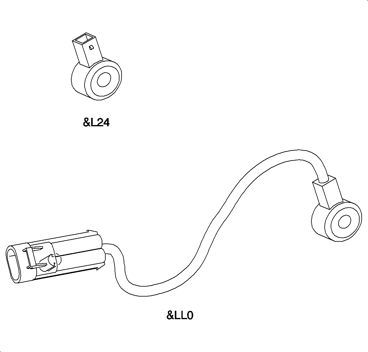
The knock sensor is located behind the engine block near the starter motor. The knock sensor is a piezoelectric flat response, wide resonant band, device that produces an AC voltage of different amplitude and frequency based on engine mechanical vibration. The amplitude and frequency are dependant upon the level of knock the sensor detects. The PCM learns a minimum noise level at idle from the knock sensor and uses stored normal noise level calibration values for the rest of the RPM band. The knock sensor signal is only used during the combustion event of the firing cylinder. When in a combustion event, the PCM filters the knock signal and compares it to the normal calibration noise level for that RPM. If the PCM has determined that knock is present during the combustion event, it will retard timing until the knock is eliminated. The PCM will always try to work back to a zero compensation level or no spark retard.
Low Coolant Level Switch
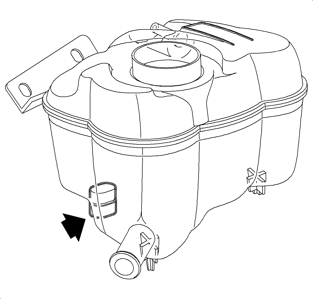
COOLANT LEVEL TELLTALE: The low coolant level switch is located in the bottom of the coolant surge tank. The low coolant level switch is used to detect engine coolant in the coolant surge tank dropping below a certain level. The switch is a normally open switch that closes when the engine coolant in the surge tank is above a certain level. The switch is supplied ignition voltage, which is used as a switch input to the PCM. When the coolant in the coolant surge tank is full, the low coolant level switch closes, ignition voltage at PCM. The PCM turns ON the Coolant Level telltale, with low coolant level, by sending a message to the I/P cluster over the class 2 link.
Manifold Absolute Pressure (MAP) Sensor - (DOHC Shown)
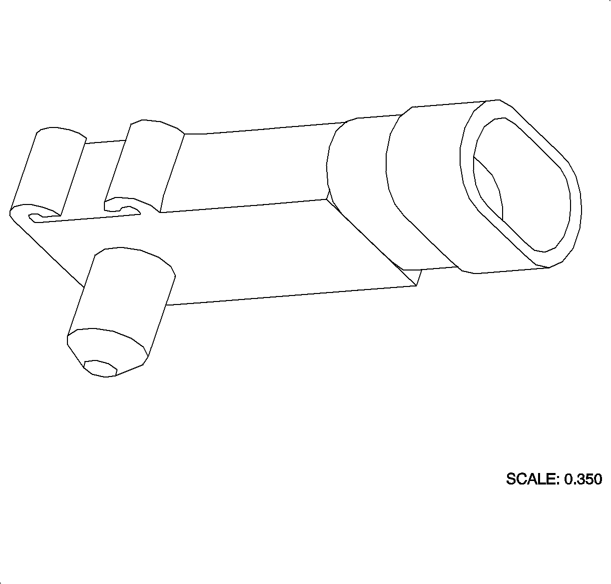
The MAP sensor is located in the intake manifold on both SOHC and DOHC 1.9L engines. The MAP sensor is a transducer that varies resistance according to changes in intake manifold pressure (vacuum). The PCM measures the signal voltage from the MAP sensor, which is a reduced value of the PCM 5 volt reference. The voltage ranges from 1-1.5 volts at idle, low pressure/high vacuum, to 4-4.5 volts at wide open throttle, high pressure/low vacuum).
The MAP sensor is primarily used for fuel control. Low intake manifold pressure indicates low engine RPM or low engine load. The higher the pressure in the intake manifold, the greater the load on the engine. The MAP sensor is also used for ignition timing, EVAP purge solenoid duty cycle, EGR operation and EGR flow diagnostics.
Altitude | Voltage Range | kPa |
|---|---|---|
BELOW 305 m (BELOW 1,000 ft) | 3.8-5.5 V | 98-100 kPa |
305-610 m (1,000-2,000 ft) | 3.6-5.3 V | 98-95 kPa |
610-914 m (2,000-3,000 ft) | 3.5-5.1 V | 95-92 kPa |
914-1219 m (3,000-4,000 ft) | 3.3-5 V | 92-89 kPa |
1219-1524 m (4,000-5,000 ft) | 3.2-4.8 V | 89-86 kPa |
1524-1829 m (5,000-6,000 ft) | 3-4.6 V | 86-83 kPa |
1829-2133 m (6,000-7,000 ft) | 2.9-4.5 V | 83-80 kPa |
2133-2438 m (7,000-8,000 ft) | 2.8-4.3 V | 80-77 kPa |
2438-2743 m (8,000-9,000 ft) | 2.6-4.2 V | 77-74 kPa |
2743-3948 m (9,000-10,000 ft) | 2.5-4 V | 74-71 kPa |
Low Altitude EQUALS High Pressure EQUALS High Voltage
Output Speed Sensor (OSS)
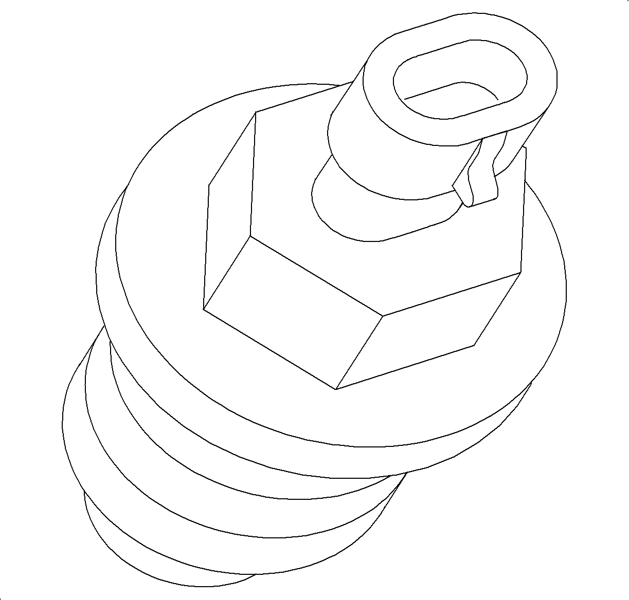
The OSS is threaded in the back of the transaxle case near the differential housing. The OSS produces an AC voltage of different amplitude and frequency depending on the velocity of the output shaft. The OSS produces the signal from 16 evenly spaced notches on the transaxle differential carrier. The OSS produces a readable AC voltage signal when vehicle speed is above 5 km/h (3 mph). The OSS signal is sent to the PCM, which is used to determine the RPM of the output shaft.
ODOMETER: The OSS produces 5,000 readable pulses/mile between 5-161 km/h (3-120 mph), which are sent to the PCM to determine vehicle speed. The vehicle speed input is used to determine the miles the vehicle has traveled. The PCM reads the OSS signal and sends vehicle speed information to the BCM over the class 2 link. The BCM in turn calculates the distance traveled and sends the information to the I/P cluster over the link. The I/P cluster increments the electronic odometer accordingly.SPEEDOMETER: The OSS voltage pulses are sent to the PCM to determine vehicle speed. The PCM averages the vehicle speed calculations over time then sends it to the I/P cluster over the class 2 link every 100 ms.
Averaging the information allows the speedometer to obtain smooth speedometer needle fluctuations.
The OSS signal is also used for many engine emission control calculations, idle speed adjustment and transaxle shift points.
Oxygen Sensor 1 (O2S-1)
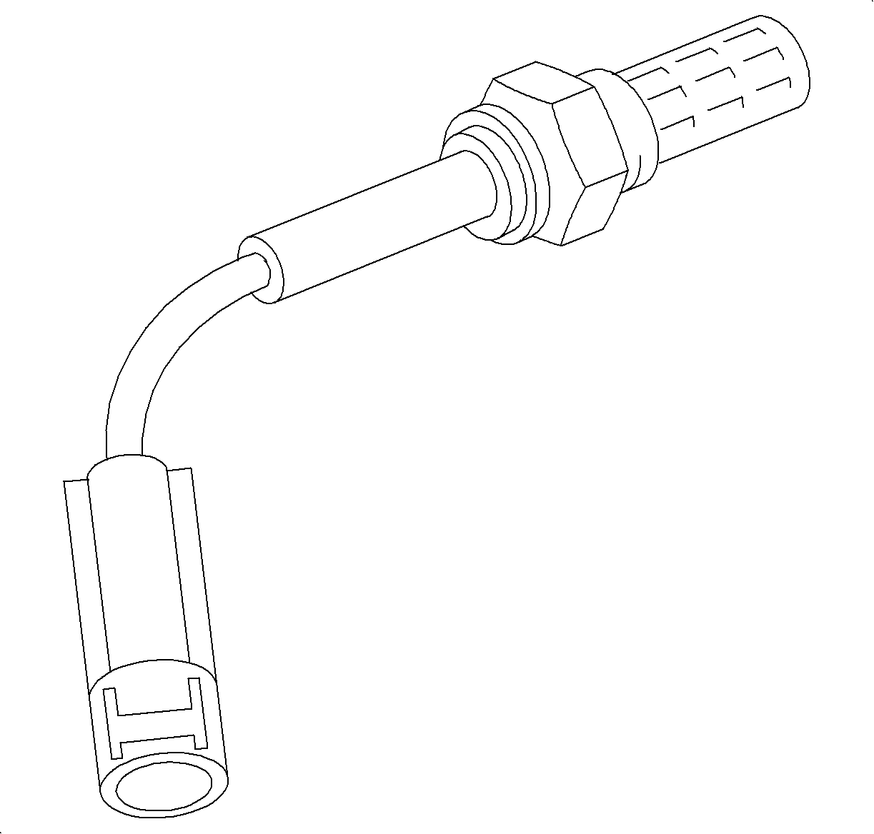
The O2S-1 is located in the exhaust manifold used by the PCM to make fuel control corrections toward a 14.7:1 air/fuel ratio. The O2S-1 is an electrical source that responds to oxygen content in the exhaust manifold. When the sensor reaches approximately 316°C (600°F), it produces a voltage based on the difference in oxygen between the atmosphere and exhaust gas. The PCM sends a bias voltage (391-491 mV) on the signal line which can be read on the scan tool when the sensor is cold. When the O2S-1 is cold, it produces no voltage and has extremely high internal resistance. However, when the sensor heats up, it produces voltage that overrides the bias voltage. This voltage is read by the PCM to determine a rich/lean O2S-1 signal used to adjust injector pulse width. Under normal conditions, low sensor voltage means high oxygen content/lean air-fuel mixture and vice versa. Normal sensor readings will fluctuate between 10-999 mV.
Powertrain Control Module (PCM)
The PCM is located underhood between the battery and power brake booster. The PCM uses one main microprocessor to control the engine and transaxle. The main function of the PCM is to control fuel and spark to the engine and to control transaxle shift points and shift feel. The PCM also controls the following:
| • | The A/C relay |
| • | The cooling fan relay |
| • | The cruise control, if equipped |
| • | The electronic variable steering assist, if equipped |
| • | The generator L-terminal voltage, needed for charging |
The PCM sends messages to the BCM or I/P cluster over the class 2 link to control the following:
| • | The coolant temp gage |
| • | The fuel gage |
| • | The CHANGE OIL SOON telltale |
| • | The charge telltale |
| • | The coolant level telltale |
| • | The coolant temp telltale |
| • | The low fuel telltale |
| • | The malfunction indicator lamp (MIL) |
| • | The oil pressure telltale |
| • | The SERVICE telltale |
| • | The speedometer |
| • | The tachometer |
| • | The upshift telltale |
The PCM uses inputs from various sensors, processes the information and commands output devices. It performs diagnostics on both input and output circuits that have associated diagnostic trouble codes (DTCs). When the circuit has failed after a series of tests, a DTC will be set and the PCM will store Freeze Frame/Failure Record information.
Stop Lamp Switch
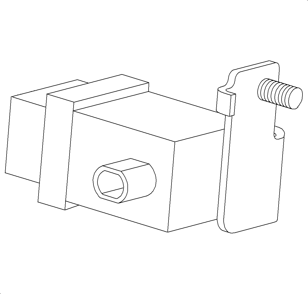
The stop lamp switch is located under the dashboard touching the brake pedal. The stop lamp switch is used to turn ON the stop lamps and to serve as an input to the PCM and cruise control module, if equipped. The stop lamp switch has 2 internal independent switches. One is used for the stop lamps and the other for the PCM/cruise control module inputs. The switch for the PCM/cruise control module is normally closed, (brake pedal released, plunger depressed, and the switch for the stop lamps is normally open, brake pedal released, plunger depressed. Ignition voltage is supplied to the PCM and cruise control module through the stop lamp switch whenever the ignition is turned ON and the brake pedal is released. When the brake pedal is depressed, the PCM/cruise control module inputs go low. The stop lamp switch is also used by the PCM as an input for transaxle downshifting and TCC operation.
Throttle Position (TP) Sensor
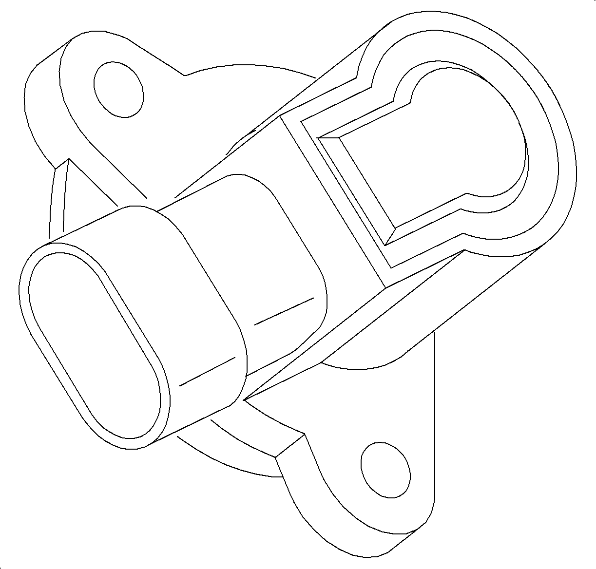
The TP sensor is located on the throttle body connected to the throttle plate shaft. The TP sensor is a potentiometer that varies resistance according to changes in throttle plate position. The PCM measures the signal voltage from the TP sensor, which is a reduced value of the PCM 5-volt reference. The voltage ranges from 0.4 (+/- 0.2) volts at 0 percent throttle position to 4.7 volts at wide open throttle.
The TP sensor is used for the following:
| • | Clear flood mode |
| • | Cruise control operation |
| • | Deceleration enleanment |
| • | IAC valve opening for throttle following |
| • | Idle determination |
| • | Transaxle shifting/TCC operation |
| • | Wide open throttle conditions |
