Park Lock Cable Replacement LHD Vehicles
Removal Procedure
- Disable the SIR System. Refer to
Enabling the SIR System
.
- Remove the console. Refer to
Console Replacement
in
Instrument Panel, Gages, and Console.
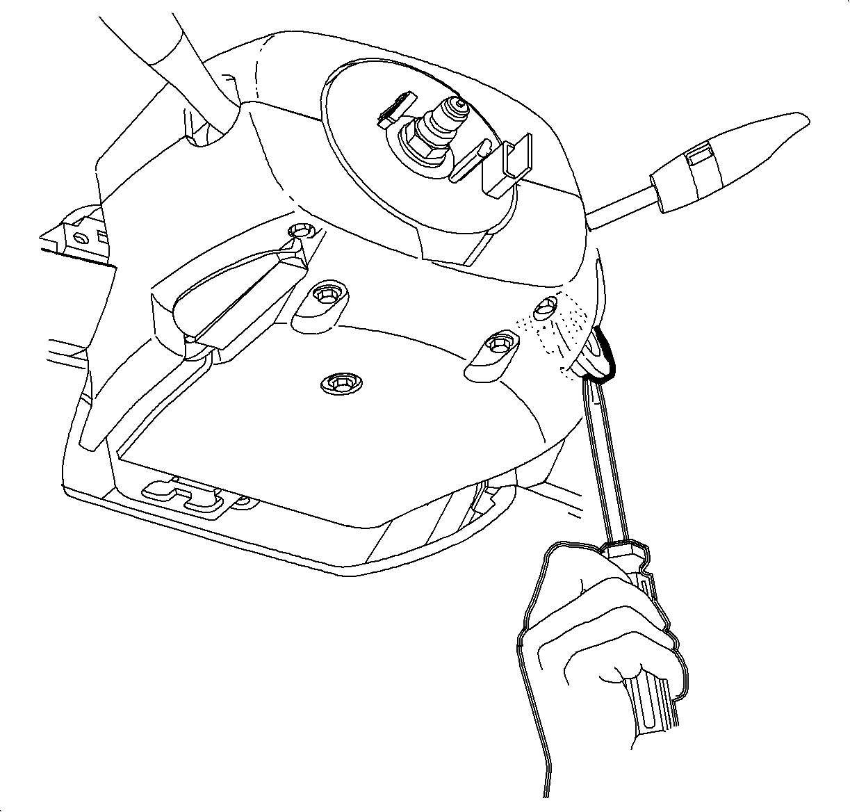
- Use a small screwdriver to gently pry the ignition bezel from the lower
column cover.
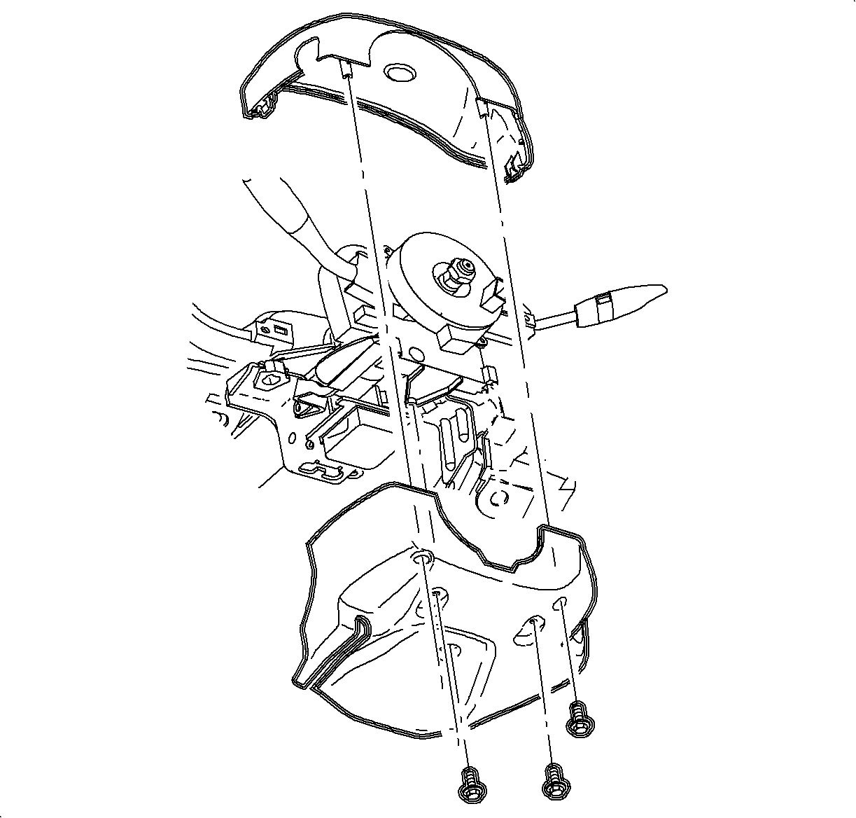
- Remove the lower column cover fasteners, upper cover, and lower cover.
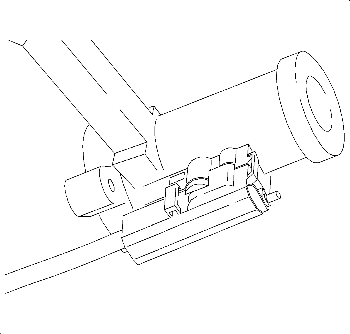
- Disengage the retaining tabs and remove the park lock cable assembly from the
ignition module.
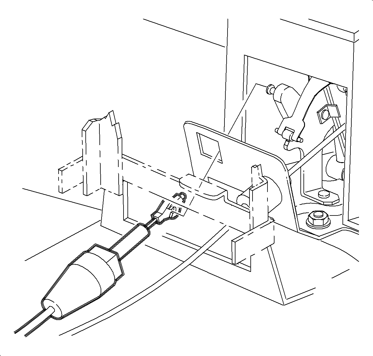
- Disconnect the end terminal of the park lock cable assembly from the plastic
lock-out lever at the control base assembly.
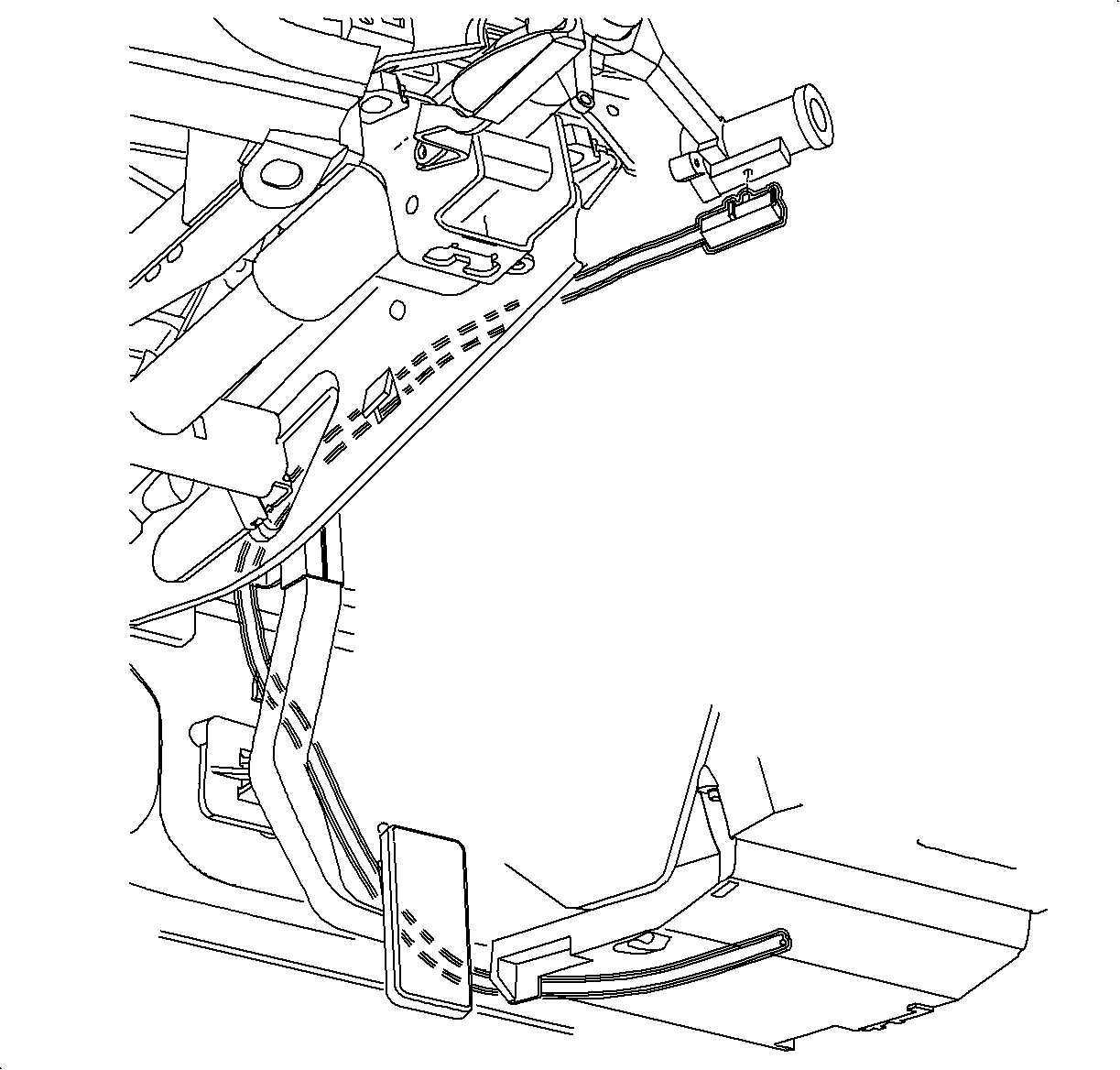
- Remove the park lock cable assembly from the vehicle and note cable routing.
Installation Procedure
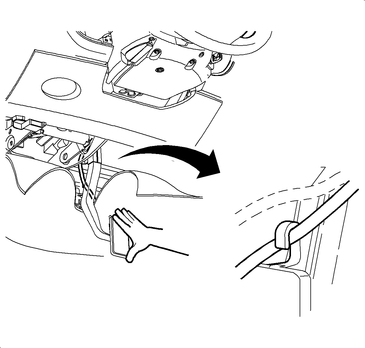
- Install the new park lock cable.
- Route the cable around the HVAC module fin.
- Route the cable through the accelerator pedal bracket retainer clip.

- Install the park lock cable fitting end to control base assembly. Be sure to
seat the fitting completely.
- Attach the park lock cable end terminal to the plastic lock-out lever
on the control assembly.
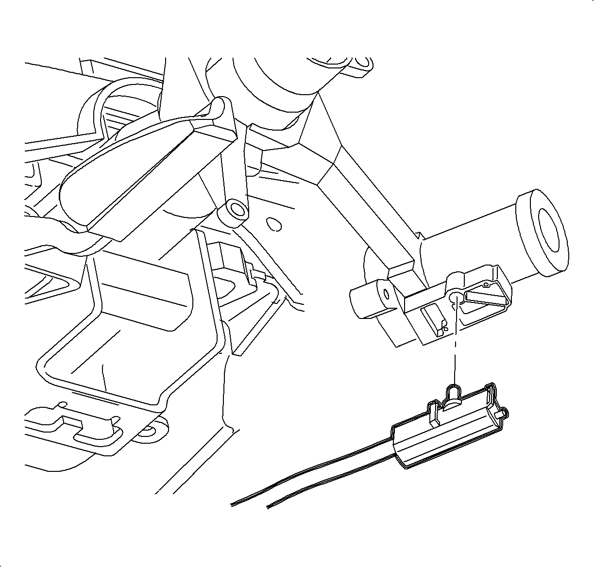
- Snap the park lock cable assembly onto the ignition module.

- Install the lower column cover, top column cover, and the fasteners.
- Install the ignition bezel.
| 8.1. | Align the peg of the ignition bezel with the cut-out in the lower shroud. |
Important: The ignition key must be in the ACC position when installing the ignition cylinder
into the ignition module.
- Adjust the park lock cable assembly. Refer to
Park Lock Cable Adjustment
.
- Install the console. Refer to
Console Replacement
in Instrument Panel, Gages, and Console.
- Enable the SIR system. Refer to
Enabling the SIR System
.
Park Lock Cable Replacement RHD Vehicles
Removal Procedure

- Disable the SIR System. Refer to
Enabling the SIR System
.
- Remove the console. Refer to
Console Replacement
in
Instrument Panel, Gages, and Console.
- Use a small screwdriver to gently pry the ignition bezel from the lower
column cover.

- Remove the lower column cover fasteners, upper cover, and lower cover.

- Disengage the retaining tabs and remove the park lock cable assembly from the
ignition module.

- Disconnect the end terminal of the park lock cable assembly from the plastic
lock-out lever at the control base assembly.
- Depress the two tabs on the end fitting of the park lock cable assembly
and remove the park lock cable assembly from the control base assembly.

- Remove the park lock cable assembly from the vehicle and note the cable routing.
Installation Procedure

- Install the new park lock cable.
- Route cable around HVAC module fin.
- Install the park lock cable fitting end to the control base assembly.
Be sure to seat the fitting completely.
- Attach the park lock cable end terminal to the plastic lock-out lever
on the control assembly.

- Snap the park lock cable assembly onto the ignition module.

- Install the lower column cover, top column cover, and the fasteners.
- Install the ignition bezel.
| 7.1. | Align the peg of the ignition bezel with the cut-out in the lower shroud. |
Important: The ignition key must be in the ACC position when installing the ignition cylinder
into the ignition module.
- Adjust the park lock cable assembly. Refer to
Park Lock Cable Adjustment
.
- Install the console. Refer to
Console Replacement
in Instrument Panel, Gages, and Console.
- Enable the SIR system. Refer to
Enabling the SIR System
.


