For 1990-2009 cars only
Removal Procedure
- Disable the SIR System. Refer to Enabling the SIR System in SIR.
- Turn the ignition to OFF.
- Remove the console. Refer to Console Replacement in Instrument Panel, Gages, and Console.
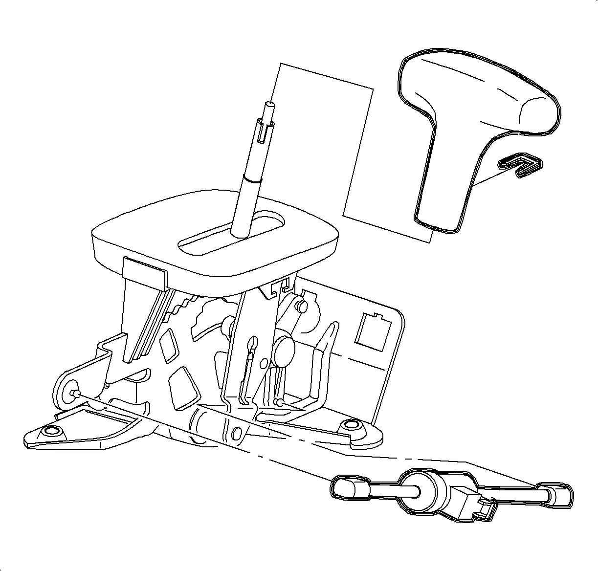
- Using a screwdriver, disconnect the control cable from the control base assembly lever.
- Depress 2 tabs on the control cable assembly and remove.
- Disconnect the park lock cable assembly from the control base assembly.
- Depress the 2 tabs on the end fitting of the park lock cable assembly and remove from the control base assembly.
- Disconnect the brake transaxle shift interlock (BTSI) harness connector.
- Remove the control indicator assembly (PRND32) bulb.
- Disconnect the 2 wiring harness retainers from the control base assembly.
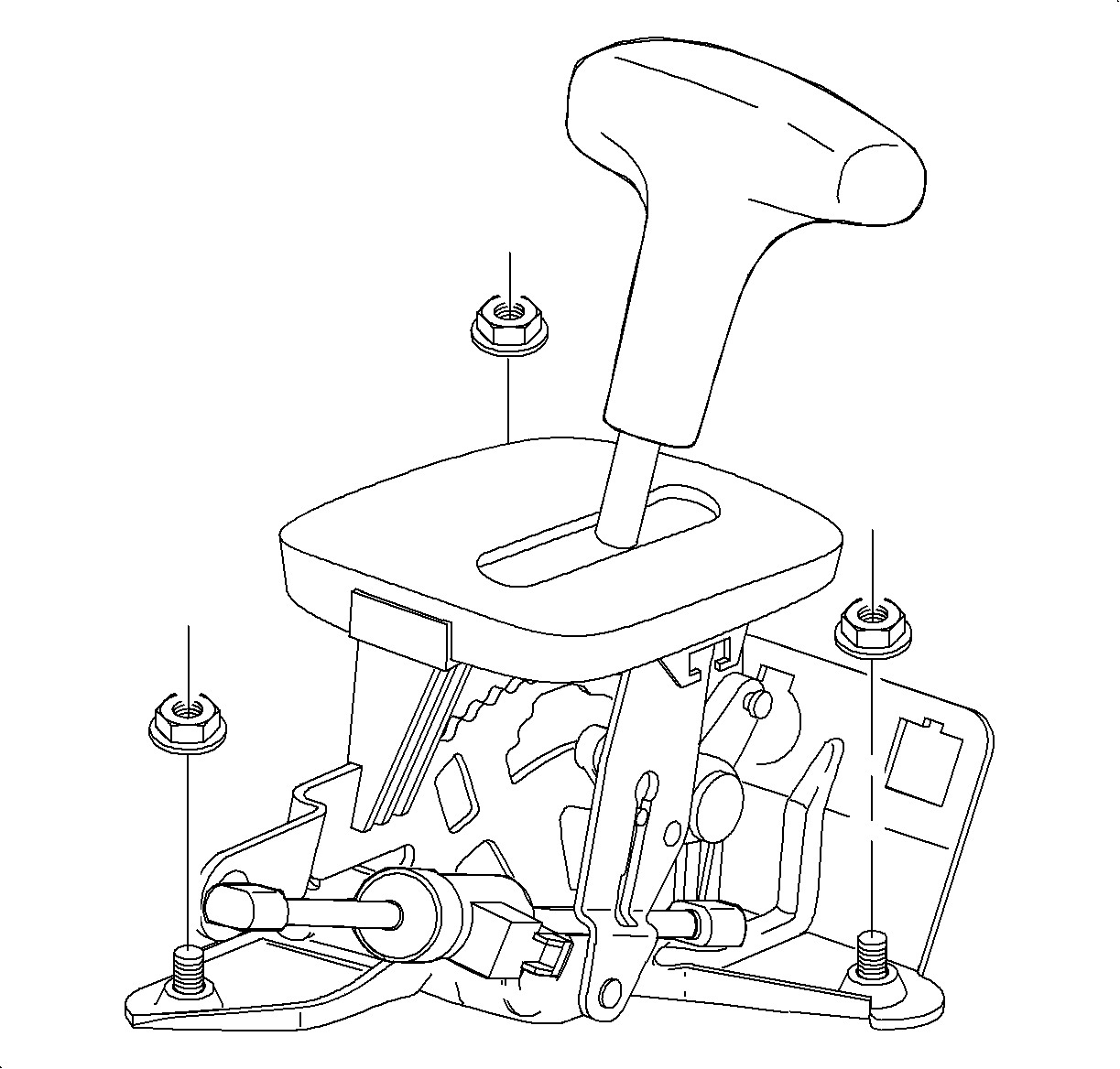
- Remove the 3 control base assembly to floor pan nuts and remove the assembly.
- With the control base assembly out of the vehicle, use a screwdriver to disconnect the BTSI solenoid plastic retainers and remove the BTSI solenoid from the control base assembly.
- Using a screwdriver, remove the control lever knob assembly retainer. Remove the control lever knob assembly.
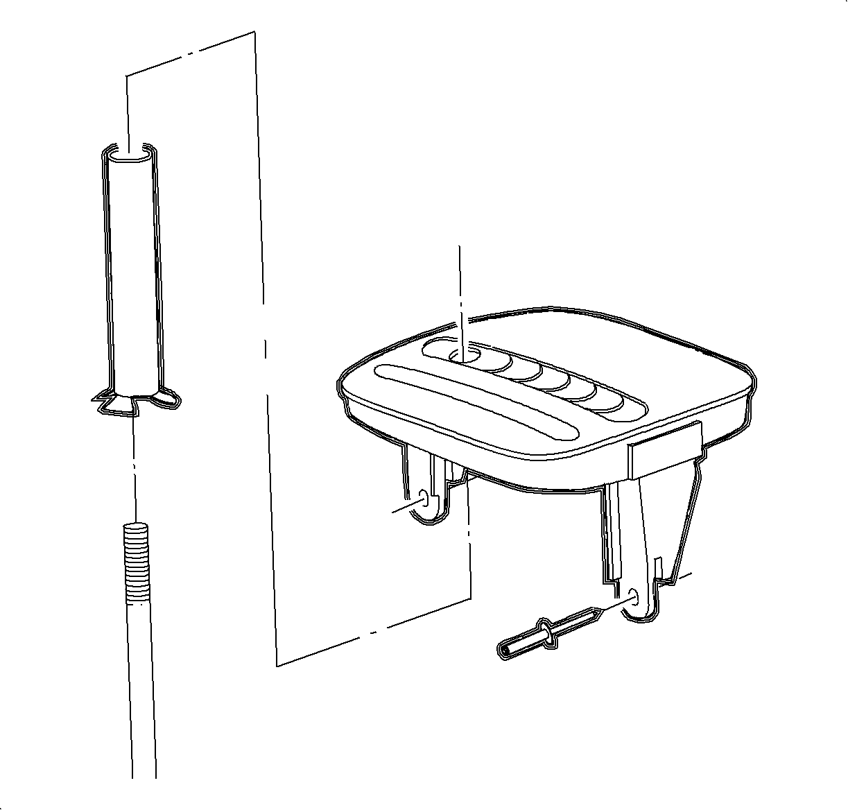
- Using a 4.75 mm (3/16 in) drill bit, drill out 2 control indicator assembly (PRND32) rivets attaching the control indicator assembly to the control shift assembly.
- Remove the control indicator assembly (PRND32) from the control base assembly of the car.
- Remove the control tube.
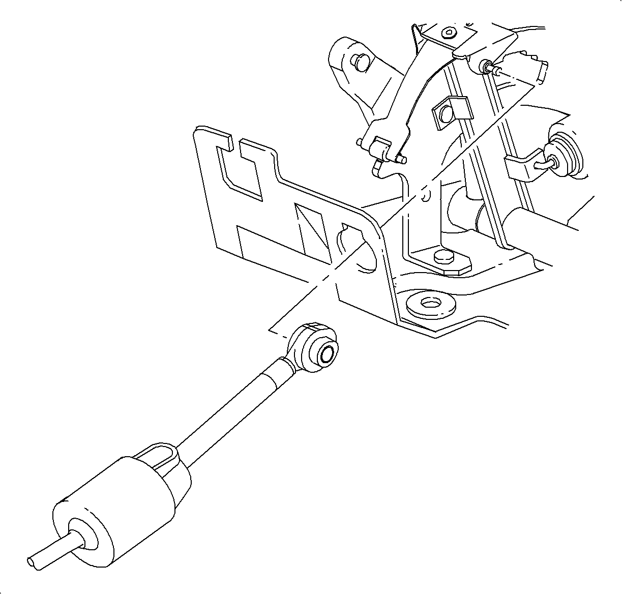
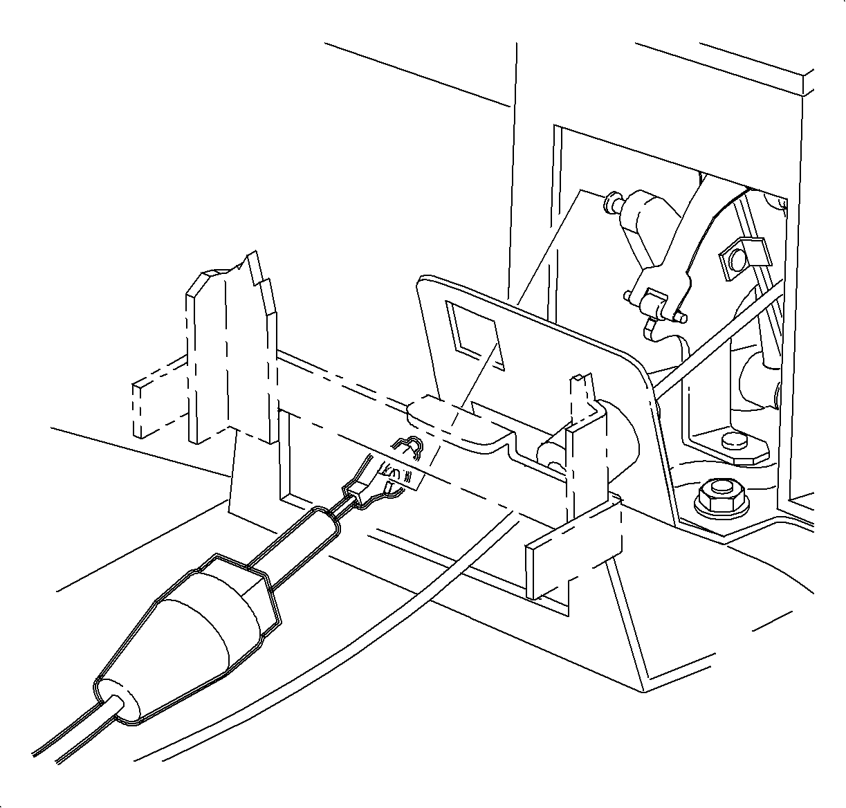
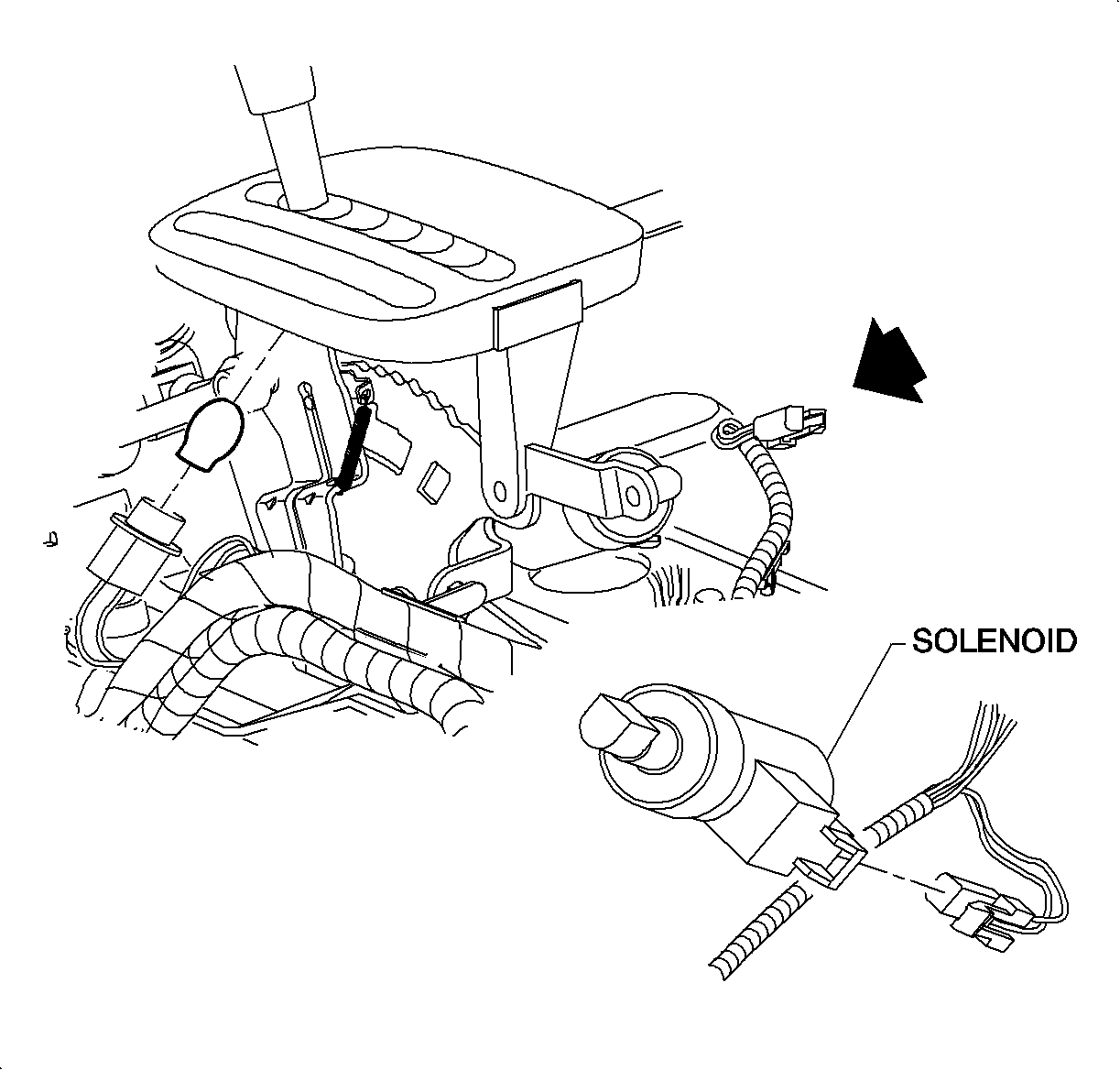
Important: For step 8, LHD illustration shown first, RHD domestic illustration shown second.

Installation Procedure
- Install the control tube on the new control base assembly.
- Position the control indicator assembly (PRND32) on the control base assembly and install 2 shift indicator pop rivets with a rivet gun.
- Install the BTSI solenoid into the control base assembly. Connect the 2 plastic retainers to the control base assembly.
- Install the control lever knob assembly and retainer.
- Position the control base assembly in the vehicle and install the 3 nuts.
- Install the control indicator assembly (PRND32) bulb.
- Connect BTSI harness connector.
- Connect 2 wiring harness retainers to the control base assembly.
- Install the park lock cable assembly into the control base assembly by completely seating the 2 tabs.
- Connect the park lock cable assembly to the control base assembly lever.
- Install the control cable assembly into the control base assembly by completely seating the 2 tabs.
- Connect the control cable assembly to the control base assembly lever, and adjust the control cable. Refer to Control Cable Adjustment.
- Verify the adjustment of the park lock cable assembly. Refer to Park Lock Cable Adjustment .
- Install the console. Refer to Console Replacement in Instrument Panel, Gages and Console.
- Enable the SIR system. Refer to Enabling the SIR System in SIR.


Tighten
Tighten the control base assembly nuts to 25 N·m (19 lb ft).

Important: For step 6, LHD illustration shown first, RHD Domestic illustration shown second.


