HVAC Module Assembly Replacement LHD Only
Removal Procedure
- Disable the SIR system. Refer to
Disabling the SIR System
in SIR.
- Record the pre-set radio stations.
Caution: Refer to Battery Disconnect Caution in the Preface section.
- Disconnect the negative battery cable.
- Recover the refrigerant using an approved refrigerant recovery system.
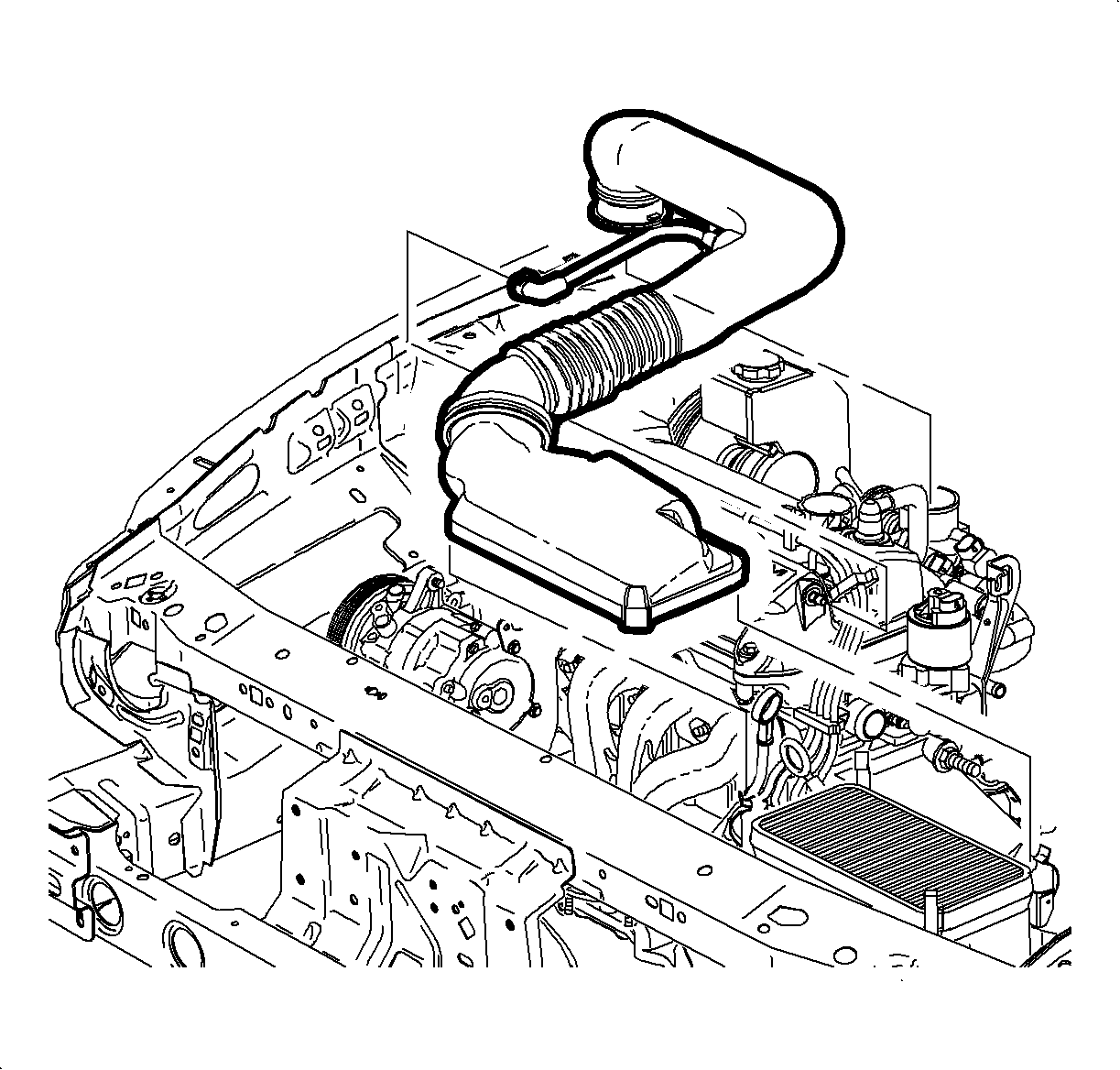
- Remove the air cleaner housing cover and the air induction hose at the
intake manifold.
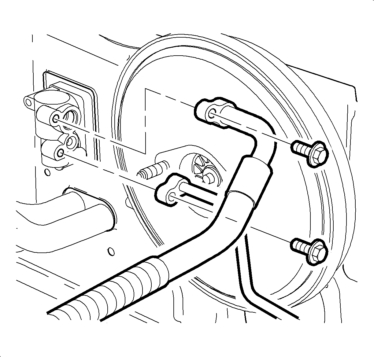
- Remove the suction hose and the liquid line from the thermal expansion valve.
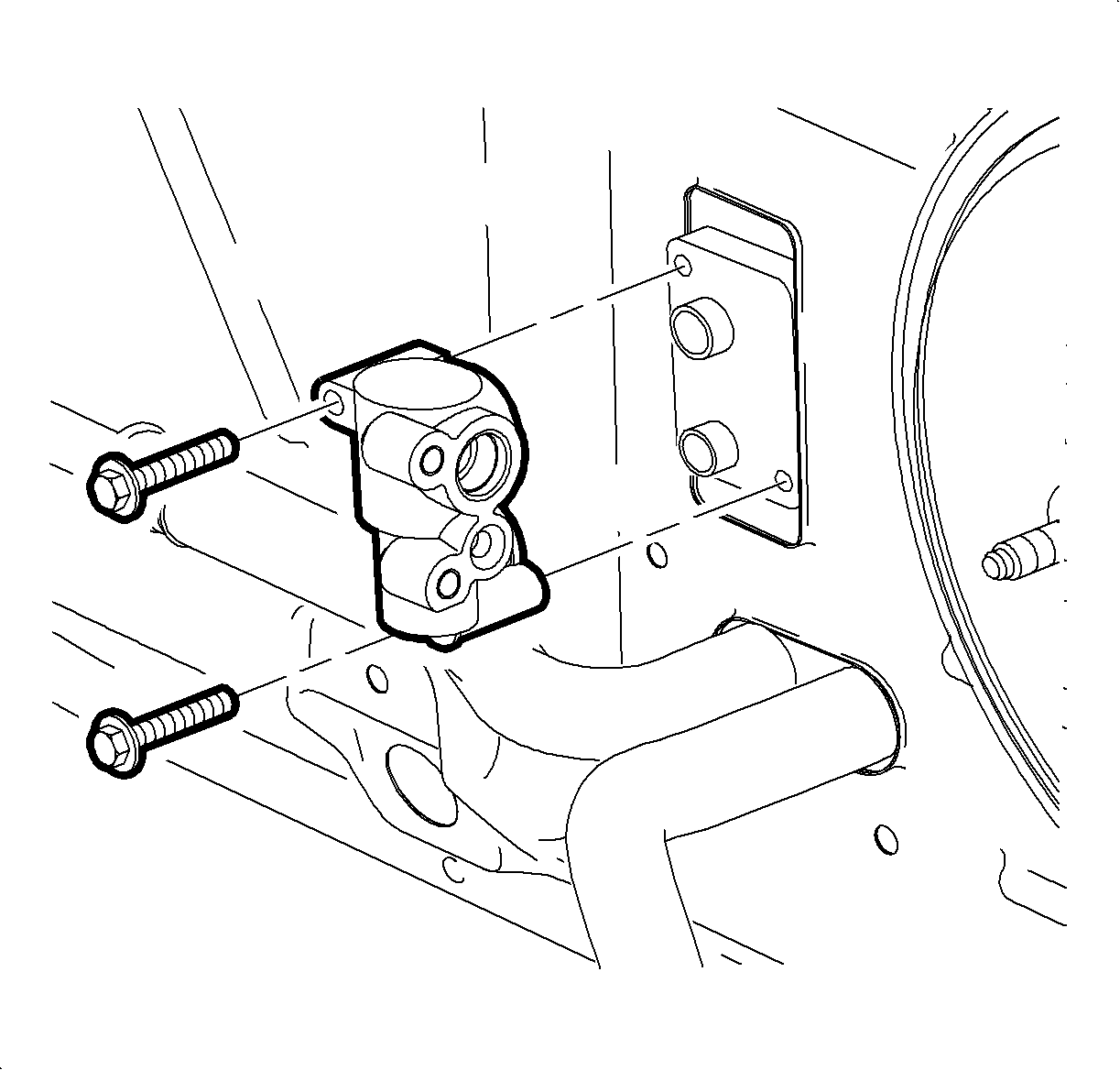
- Remove the thermal
expansion valve from the evaporator.
Notice: Place protective covers over A/C hoses, lines, TXV, and HVAC module to prevent
contamination of A/C system.
- Remove the coolant reservoir cap.
- Drain the cooling system.
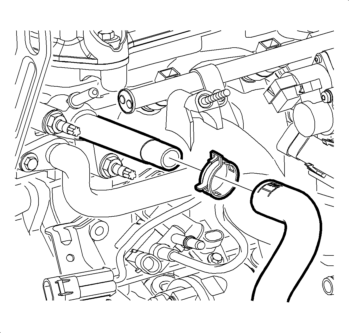
- Remove the heater inlet hose from the engine outlet and blow the remainder of
the coolant out of the heater core with an air hose in order to prevent coolant
from spilling on the vehicle interior when removing the HVAC module.
- Install the heater inlet hose on the engine outlet and position the clamp
at the 4 o'clock position as viewed from the left side of the vehicle.
Caution: Refer to Vehicle Lifting Caution in the Preface section.
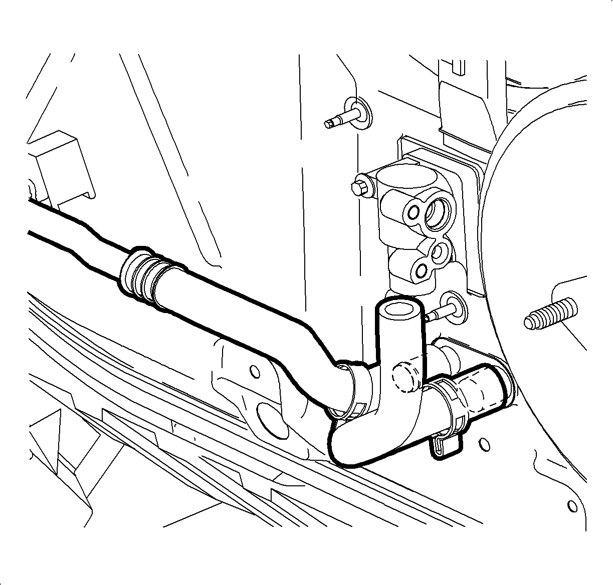
- Raise the vehicle. Refer to
Lifting and Jacking the Vehicle
in General Information.
- Move the clamps up the heater core inlet and outlet hoses.
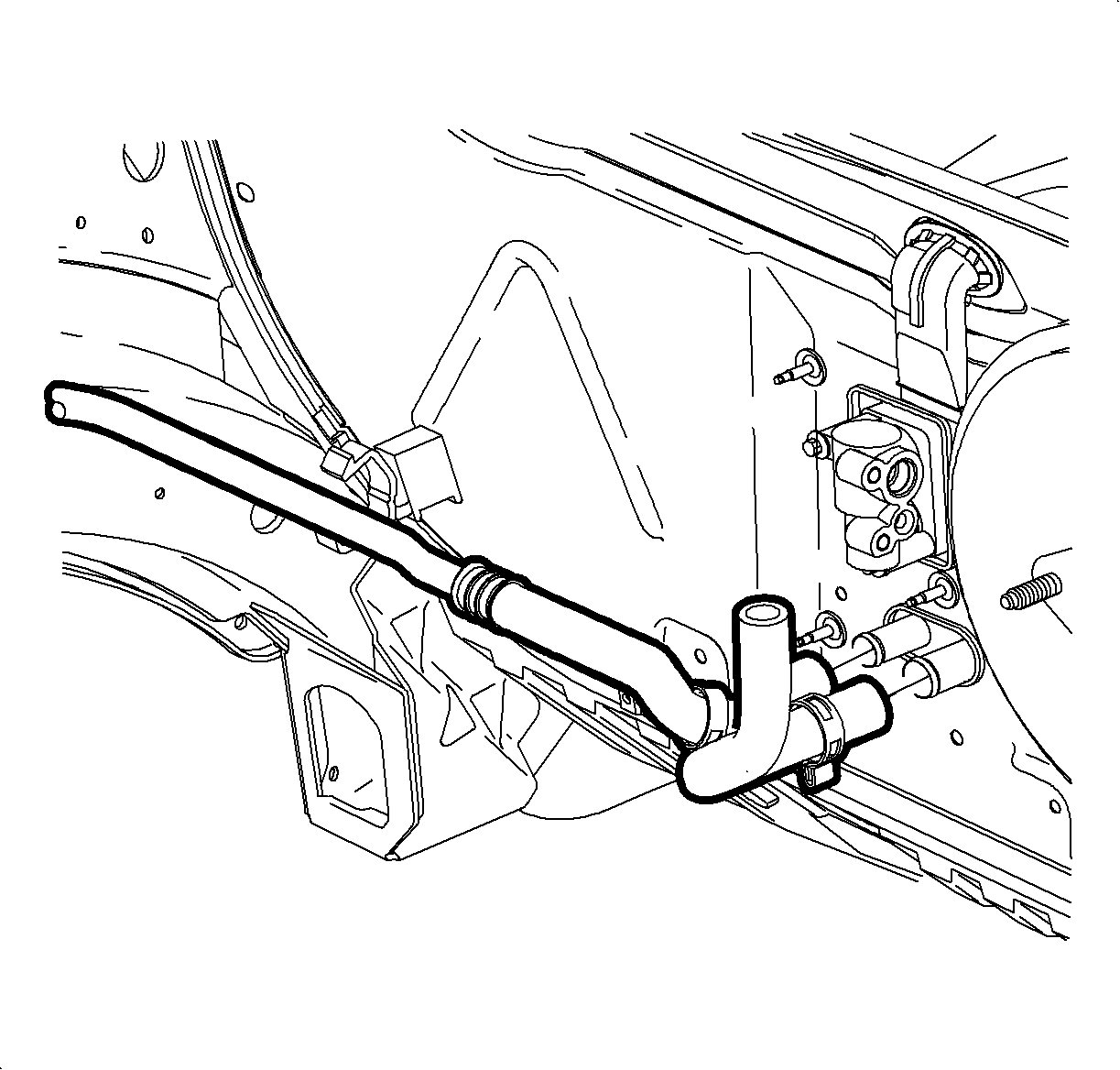
- Remove the hoses from the heater core.
- Lower the vehicle.
- Apply the parking brake lever.
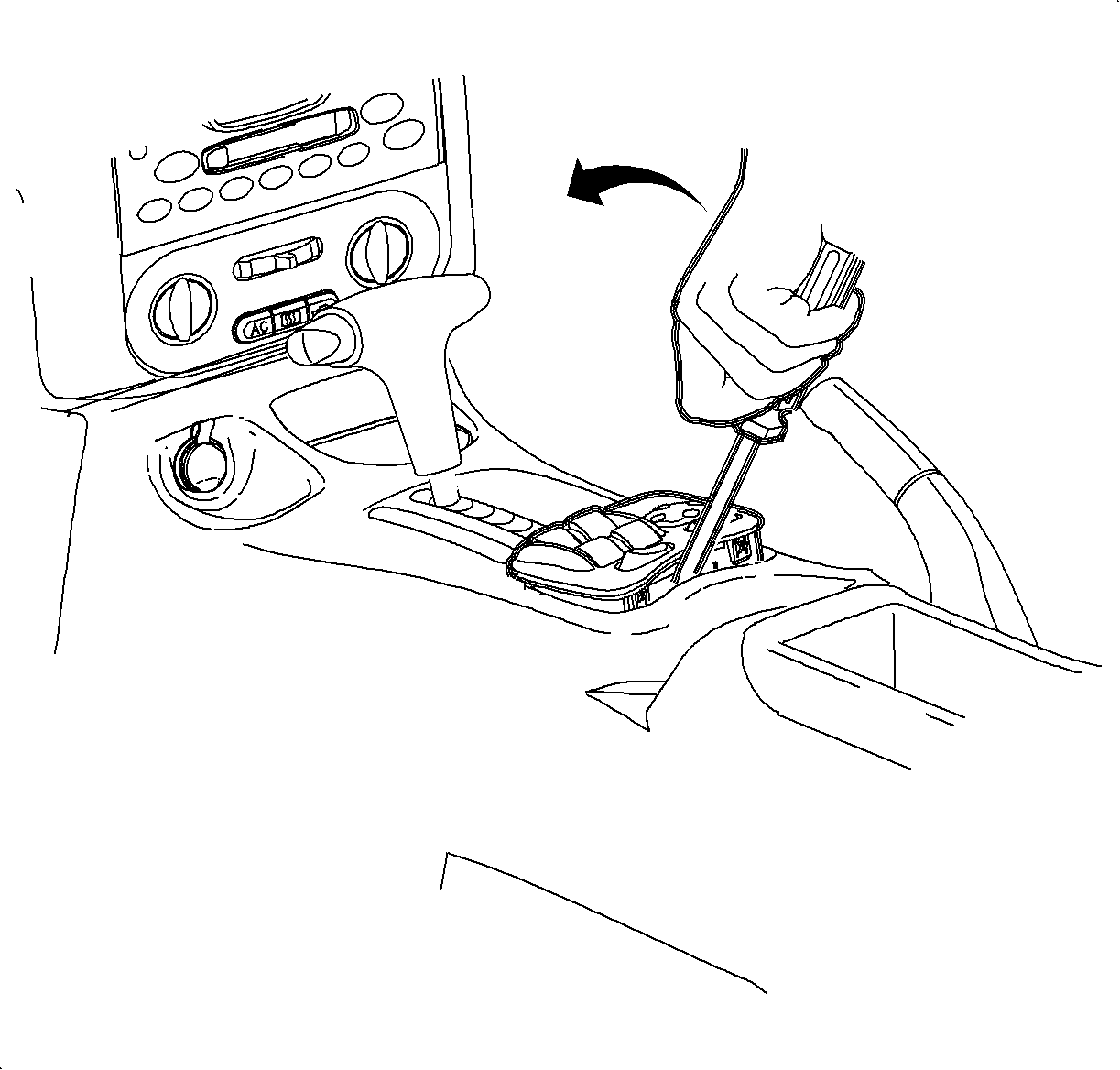
- Remove the window/mirror switch, if equipped.
| 17.1. | Using a small flat blade screwdriver, carefully lift the switch. |
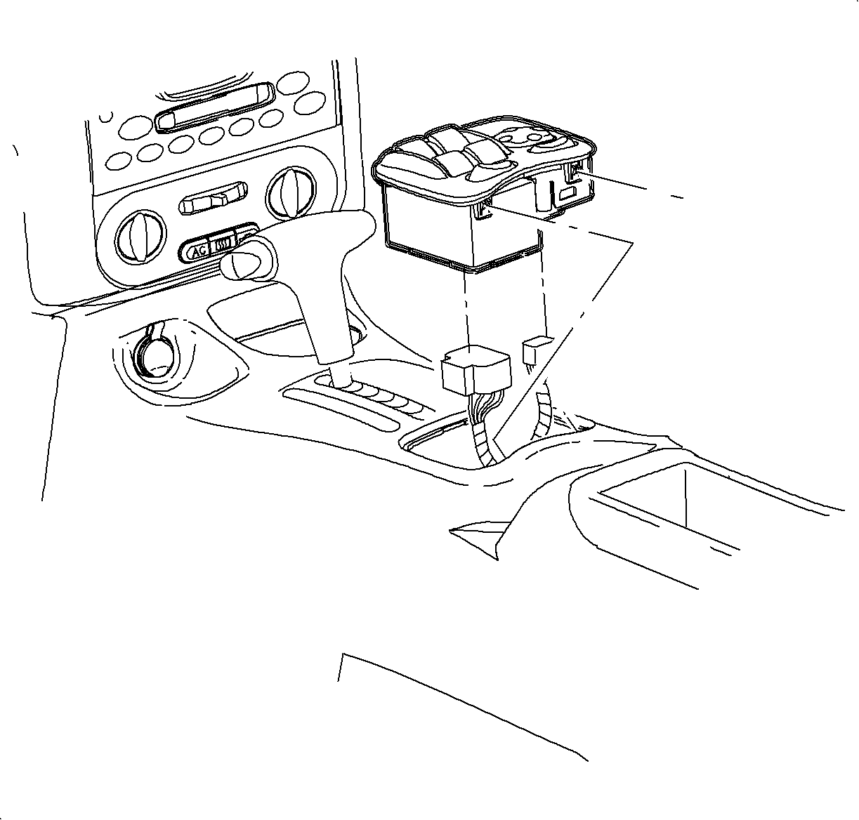
| 17.3. | Disconnect the electrical connectors by locating the retention tabs and
disengaging the connections. |
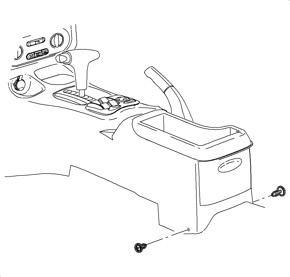
- Remove the console:
| 18.1. | Select neutral for the transaxle gear, on automatic transaxles. |
| 18.2. | Adjust the front seats to the most forward position. |
| 18.3. | Remove the rear console screws. |
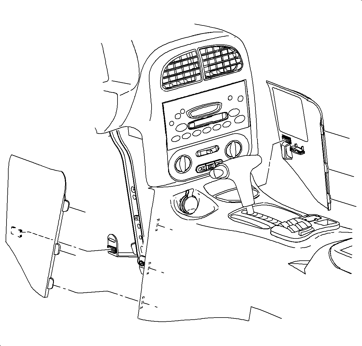
| 18.4. | Adjust the front seats to most rearward position. |
| 18.5. | Remove the left and right lower trim panel extensions by pulling outward
at the dual lock locations. |
| 18.6. | Rotate the panels outward to disengage the hinges from the console. |
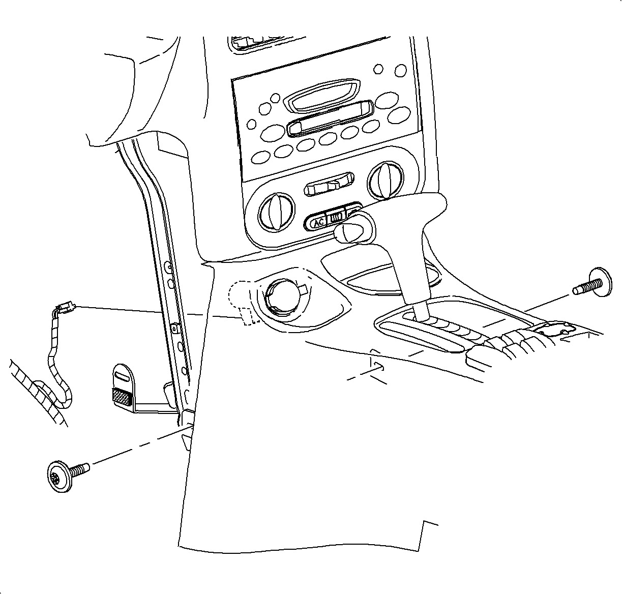
| 18.7. | Remove the front console screws. |
| 18.8. | Move the console rearward. |
| 18.9. | Disengage the retaining tabs and disconnect the power outlet connector. |
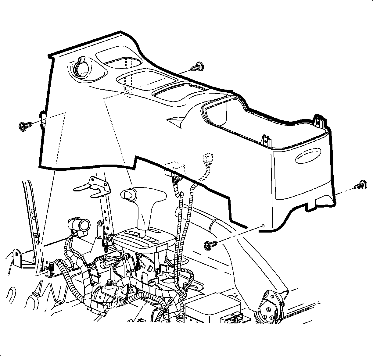
| 18.10. | On automatic equipped vehicles, press and tape the gear selector button into
the clear shifter opening. |
| 18.11. | Maneuver the console beyond the gear selector and parking brake by lifting
the rear of the console. |
| 18.12. | Remove the console from the vehicle. |
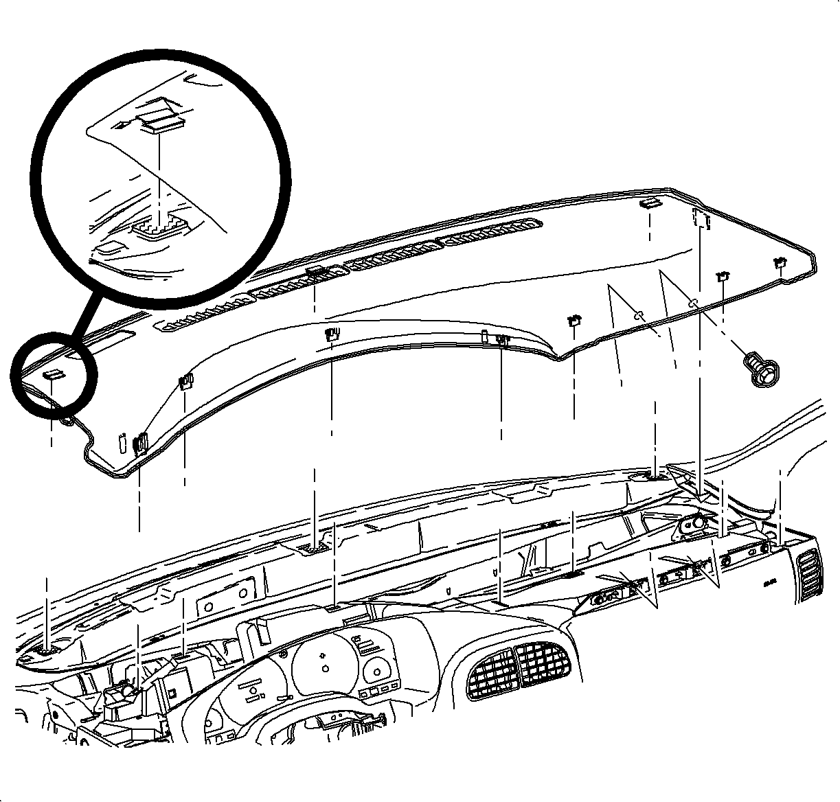
- Remove the I/P top cover:
| 19.1. | Remove the 2 screws located under the upper trim panel on the passenger's
side of the vehicle. |
| | Notice: Be careful not to damage the VIN plate when removing or replacing the upper
trim panel.
|
| 19.2. | Disengage the clips at the locations by grasping the edges of
the instrument panel upper trim and lifting up. |
| 19.3. | Disengage the hook-and-loop attachments at the rear of the instrument
panel upper trim by reaching under the panel and lifting straight up. |
| 19.4. | Raise the instrument panel upper trim enough to clear the VIN plate. |
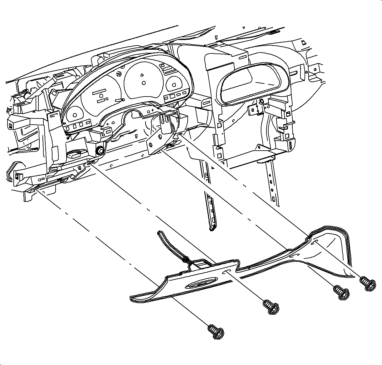
- Remove the steering column filler panel screws.
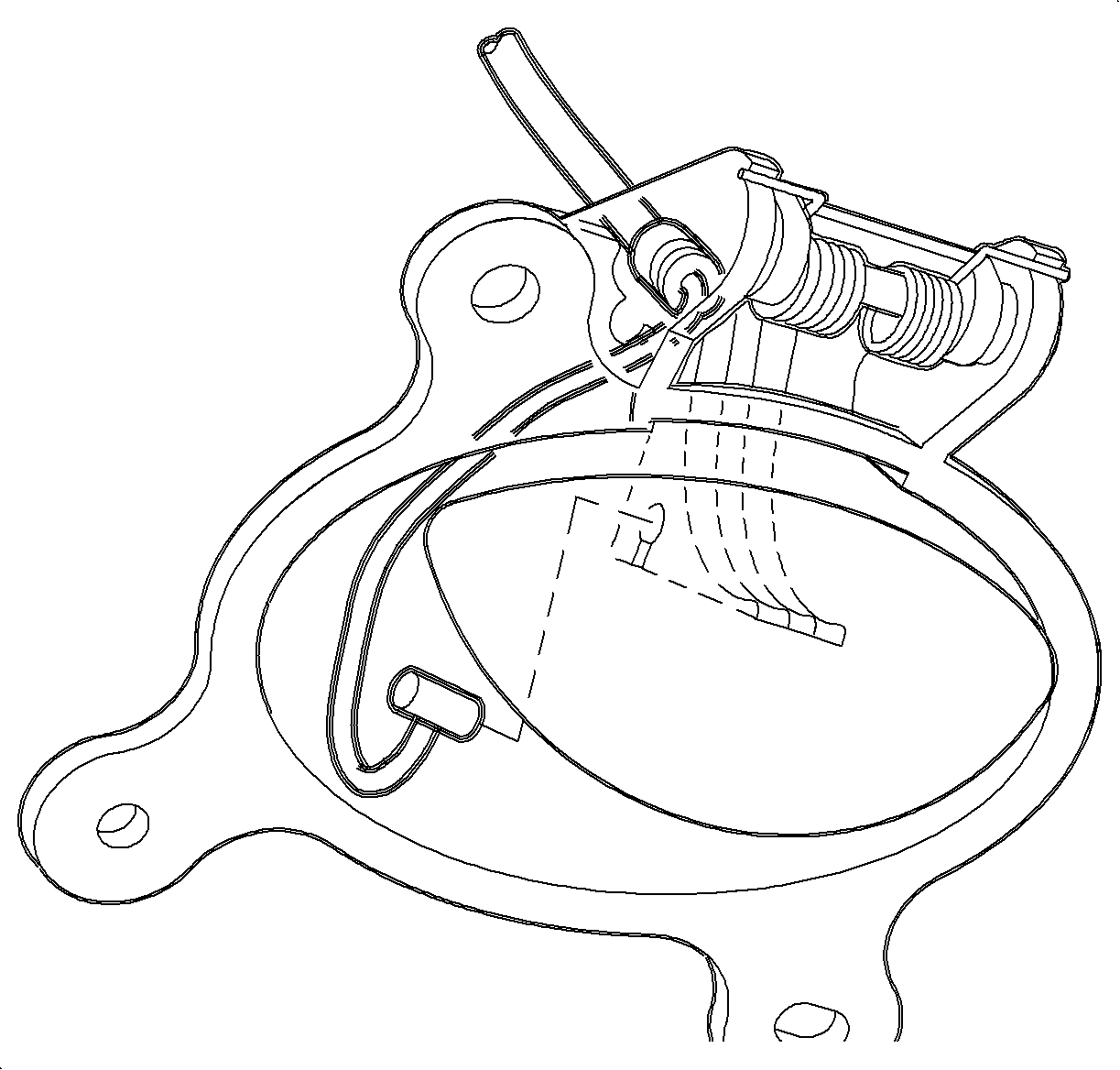
- Remove the hood release cable from the lever by releasing the cable housing,
then rotating the cable downward to the cutout.
- Remove the steering column filler panel.
Notice: Do not remove weatherstrips. Adhesion will be lost if removed.
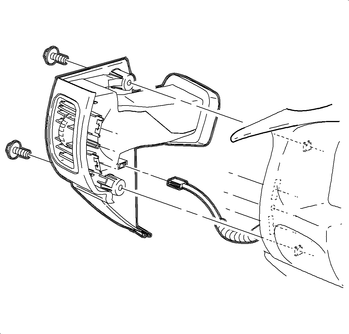
- Remove the left endcap assembly:
| 23.2. | Carefully disengage the clips at the I/P retainer assembly locations.
Use of a blunt tool will aid in disengaging the clips. |
| 23.3. | Maneuver the assemblies past the inner I/P retainer assembly and weatherstrips. |
- Remove the wiring harness from the door jamb switch.
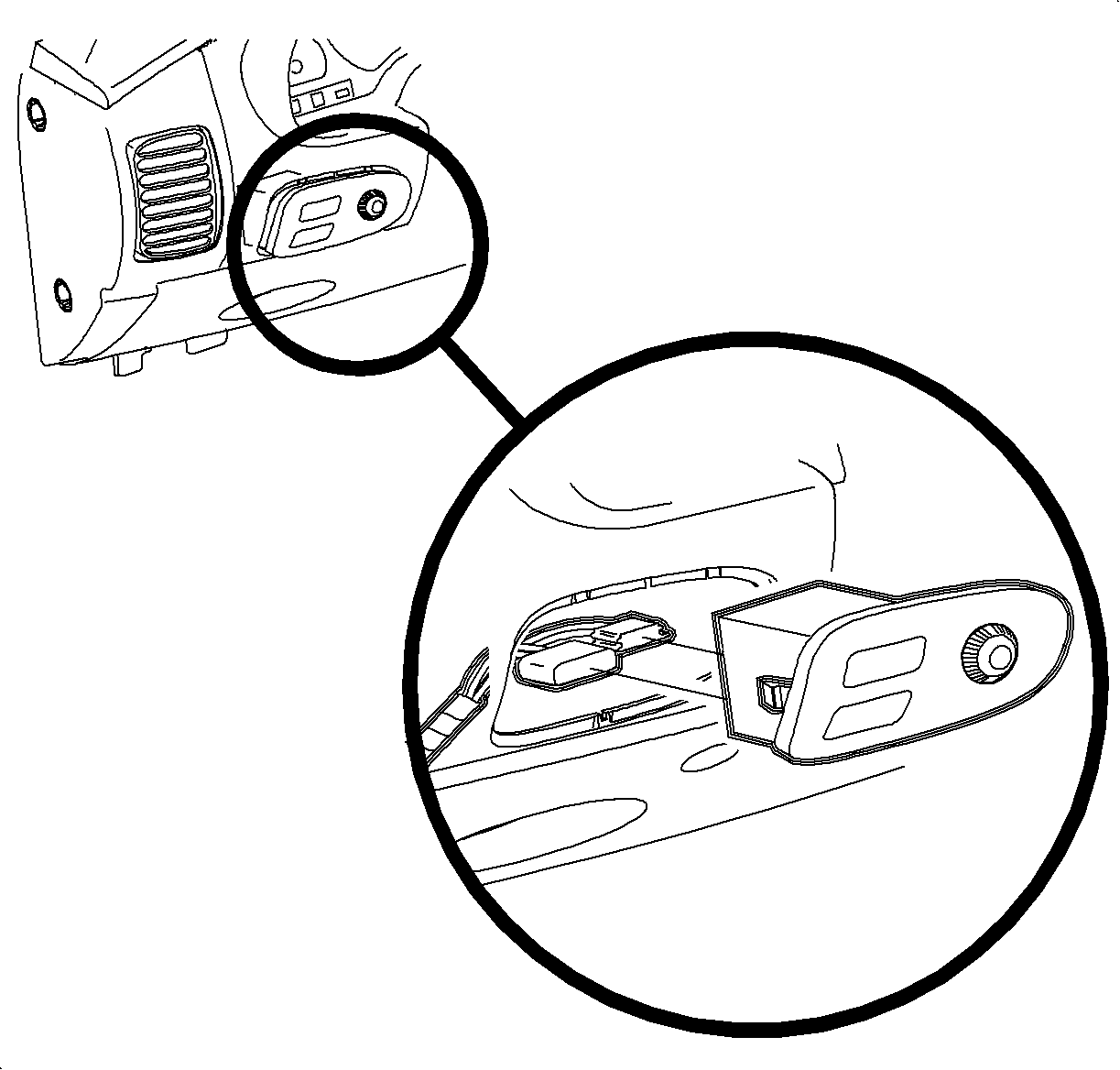
- Remove the dimmer/traction switch assembly:
| 25.1. | Use a blunt tool to pry and depress the retaining tab on the left side
of the switch housing. |
| 25.2. | Depress the wiring connector tabs and remove the harnesses from the switch. |
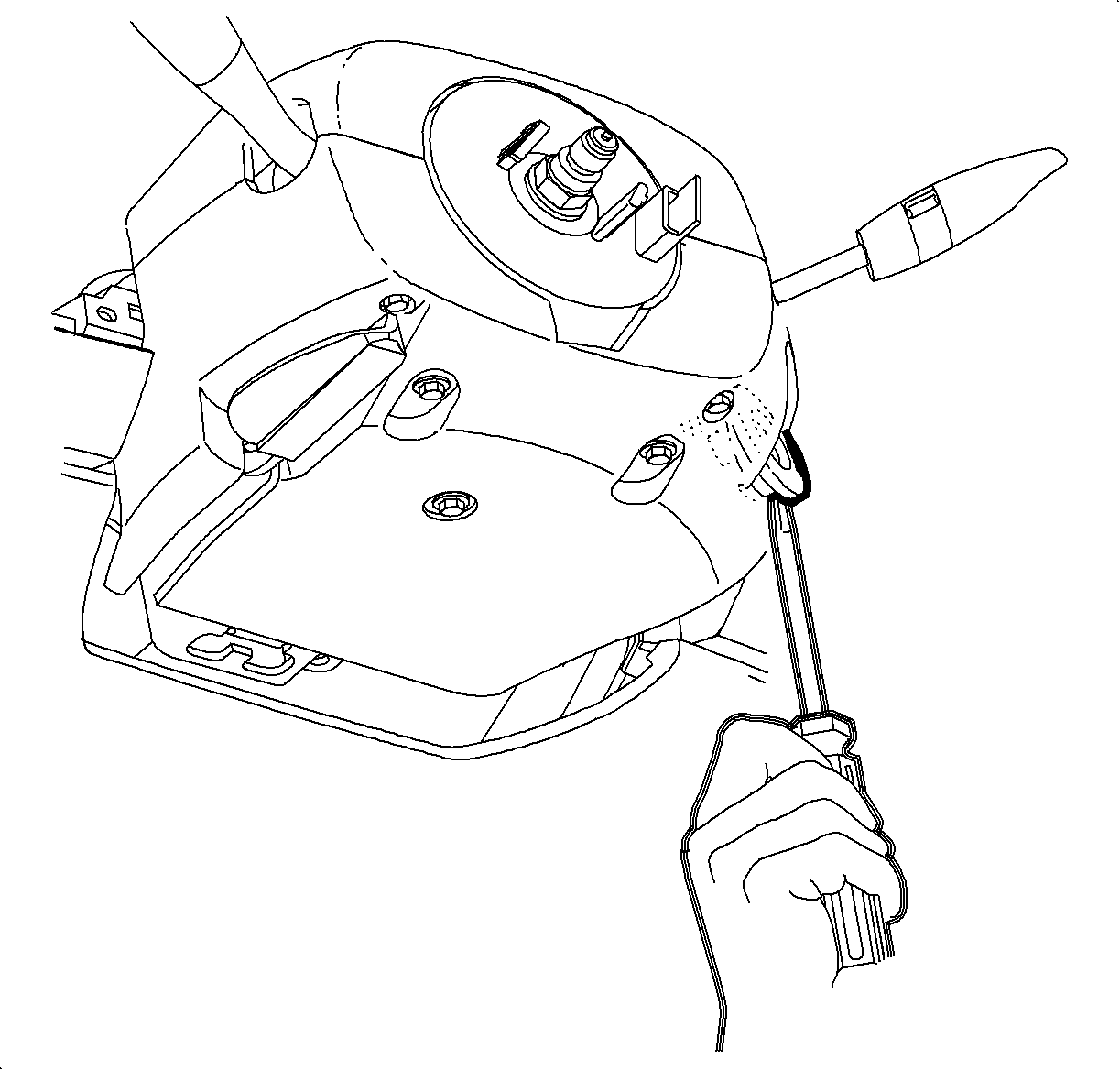
- Gently pry the edges of the ignition lock bezel with a blunt tool and separate
from the lower shroud.
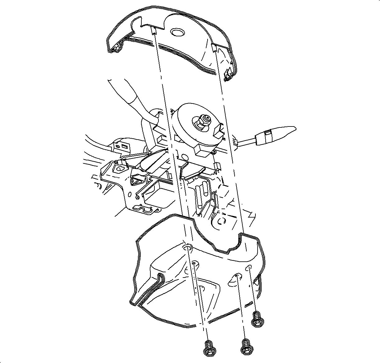
- Remove the screws and the lower steering column shroud.
- Lower the steering column by pushing down on the steering column adjusting
handle.
- Lift and remove the upper shroud from the steering column.
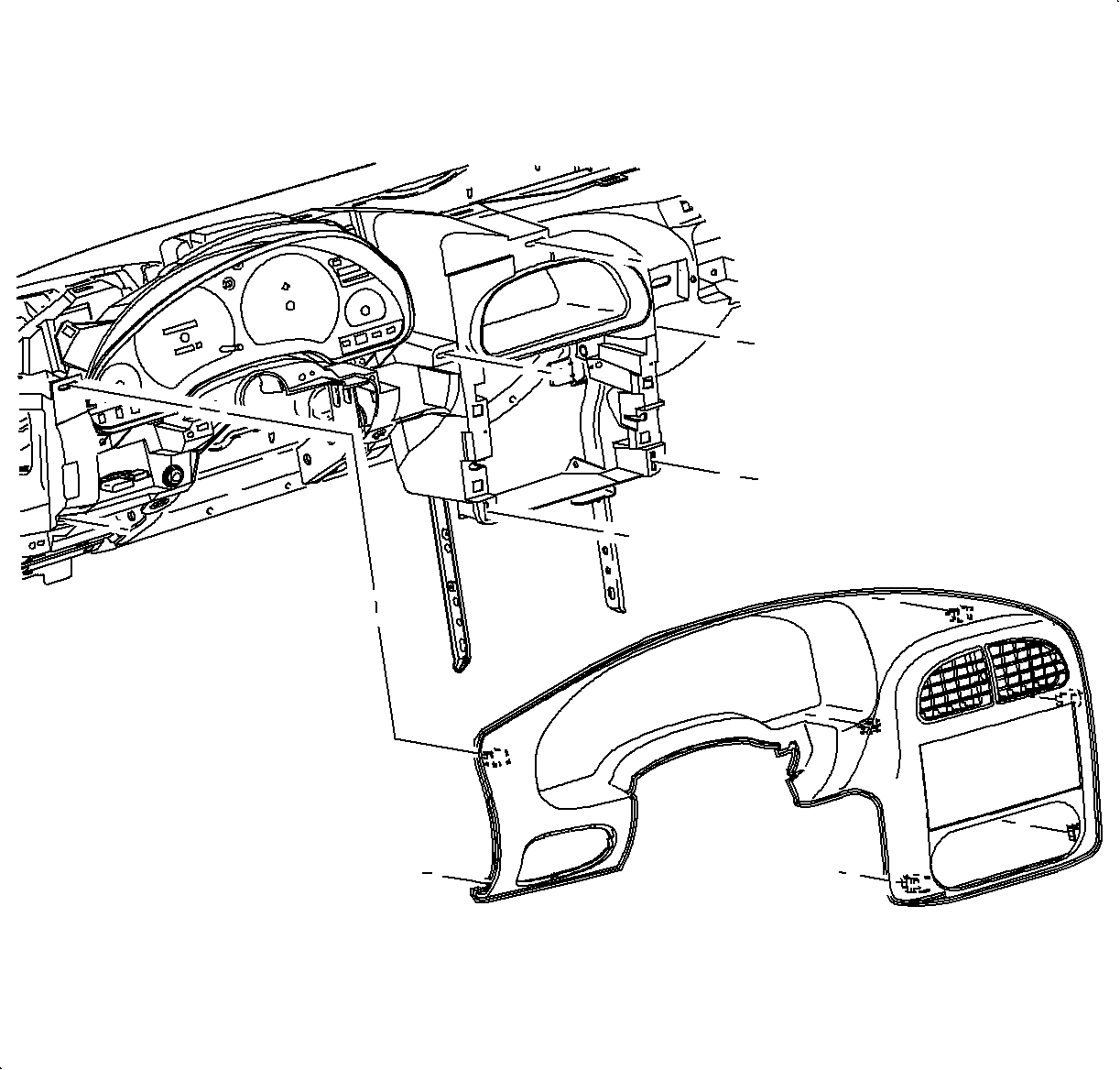
- Remove the I/P cluster bezel:
Disengage the clips from the retainer assembly by grasping the edges of the
bezel near the clip locations and pull outward.
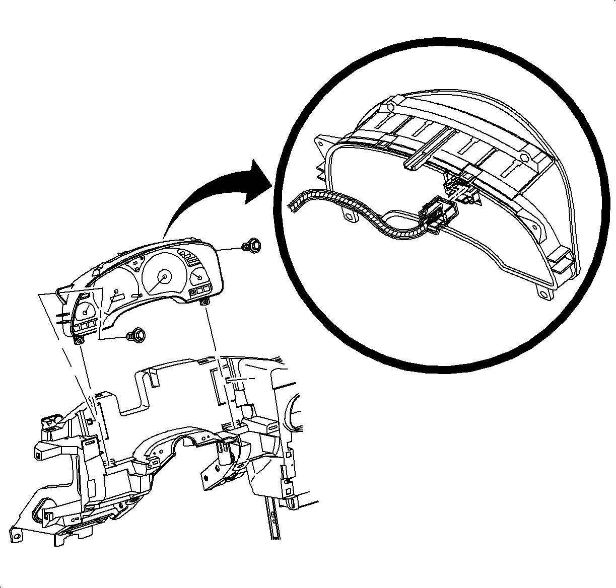
- Remove the I/P cluster:
| 31.2. | Disconnect the electrical connector from the I/P cluster by squeezing
the tabs on each side of the connector. |
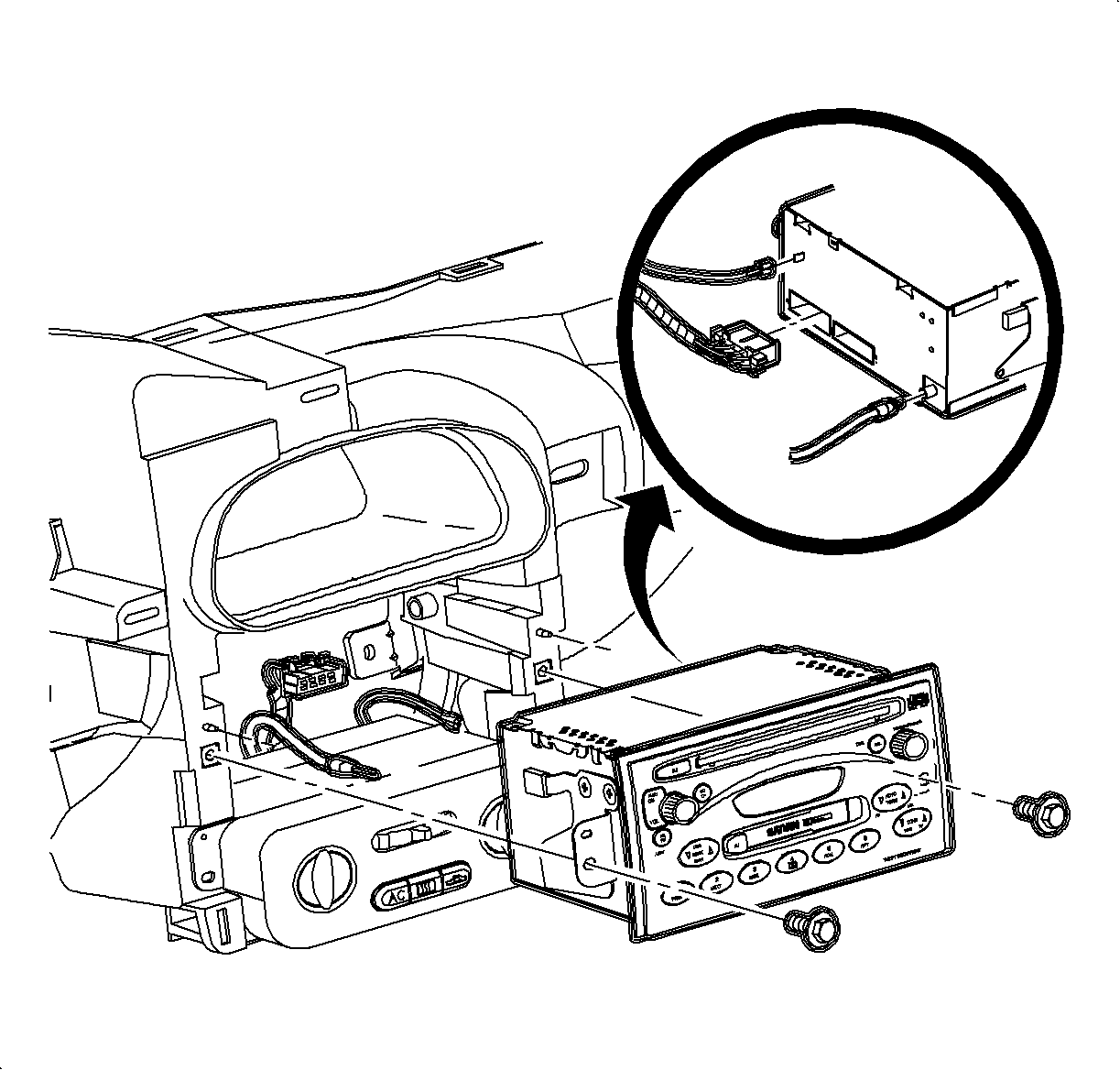
- Remove the radio:
| 32.1. | Remove the radio screws. |
| 32.2. | Pull the radio out slightly to access the rear. |
| 32.3. | Disconnect the electrical connector, antenna, and ground strap connector. |
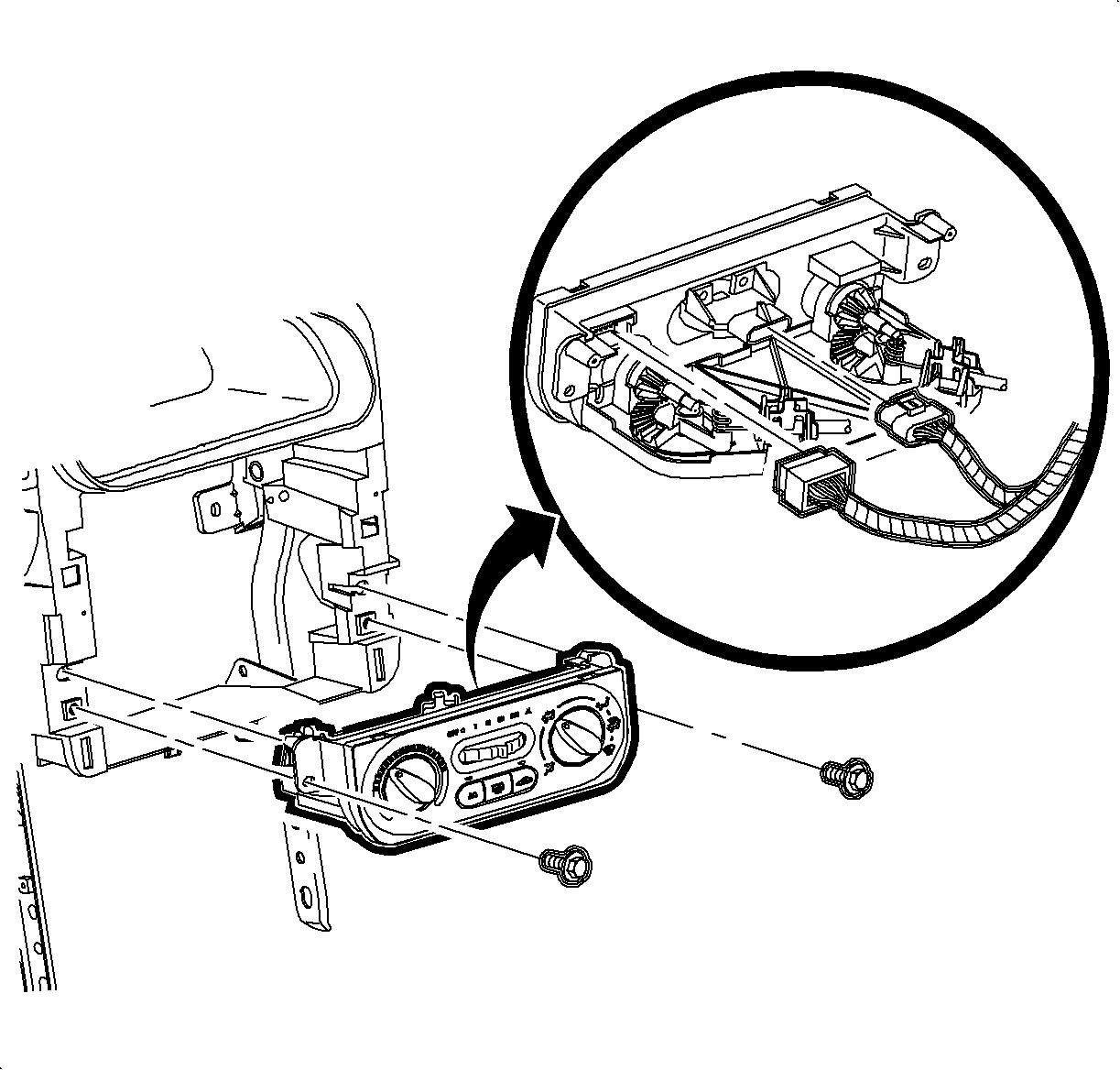
- Remove the HVAC Controller:
| 33.2. | Disconnect the HVAC blower switch connector. |
| 33.3. | Disconnect the HVAC control head connector. |
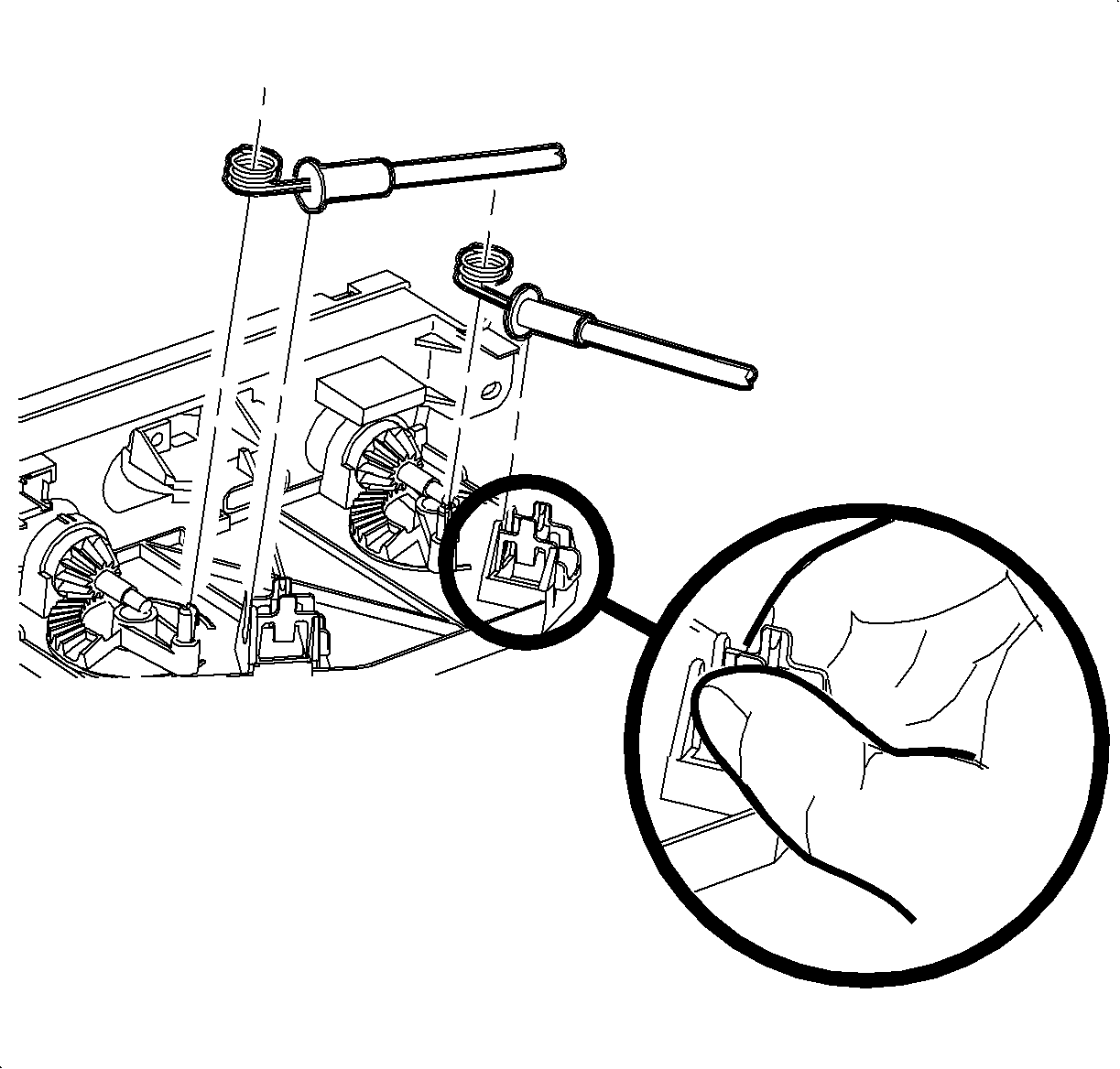
| 33.4. | Remove the temperature cable by squeezing the lock tabs together while pulling
the coiled end cable straight up beyond the retaining tabs. |
| 33.5. | Remove the mode cable by squeezing the lock tabs together while pulling
the coiled end cable straight up beyond the retaining tabs. |
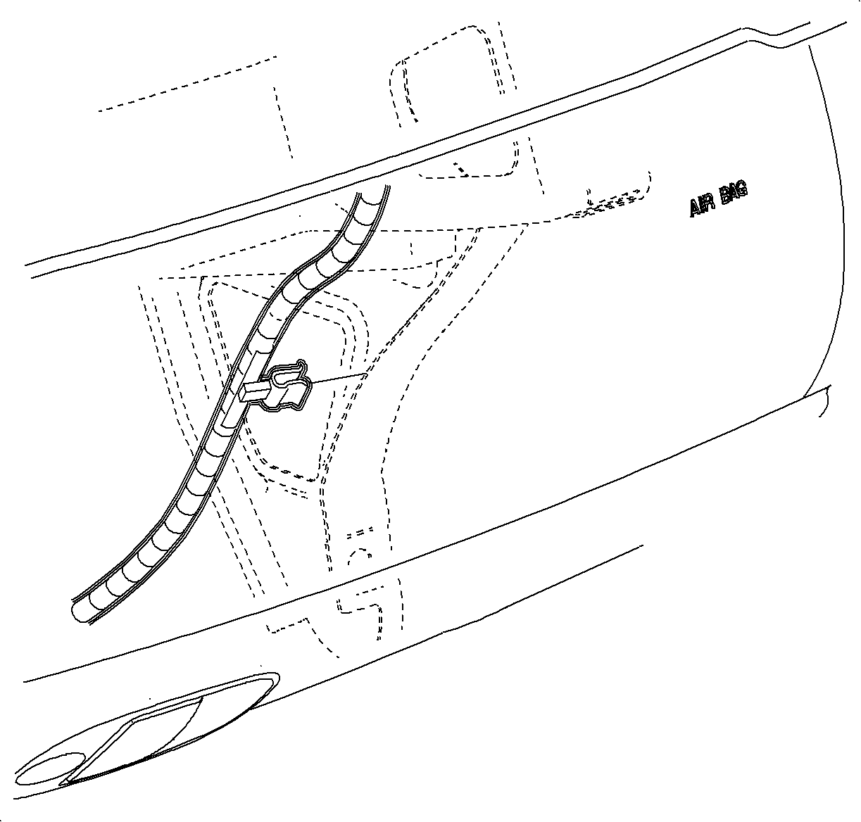
- Disengage the door jamb switch wiring harness retainer, metal clip. Remove the
left and right harnesses from the I/P retainer assembly.
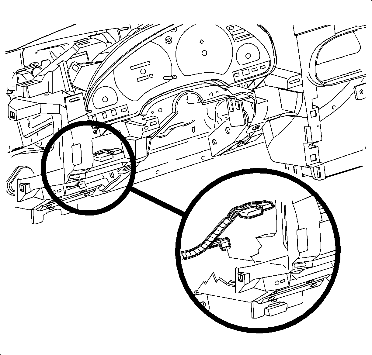
- Disengage the dimmer/traction control switch wiring harness from the retainer
assembly.
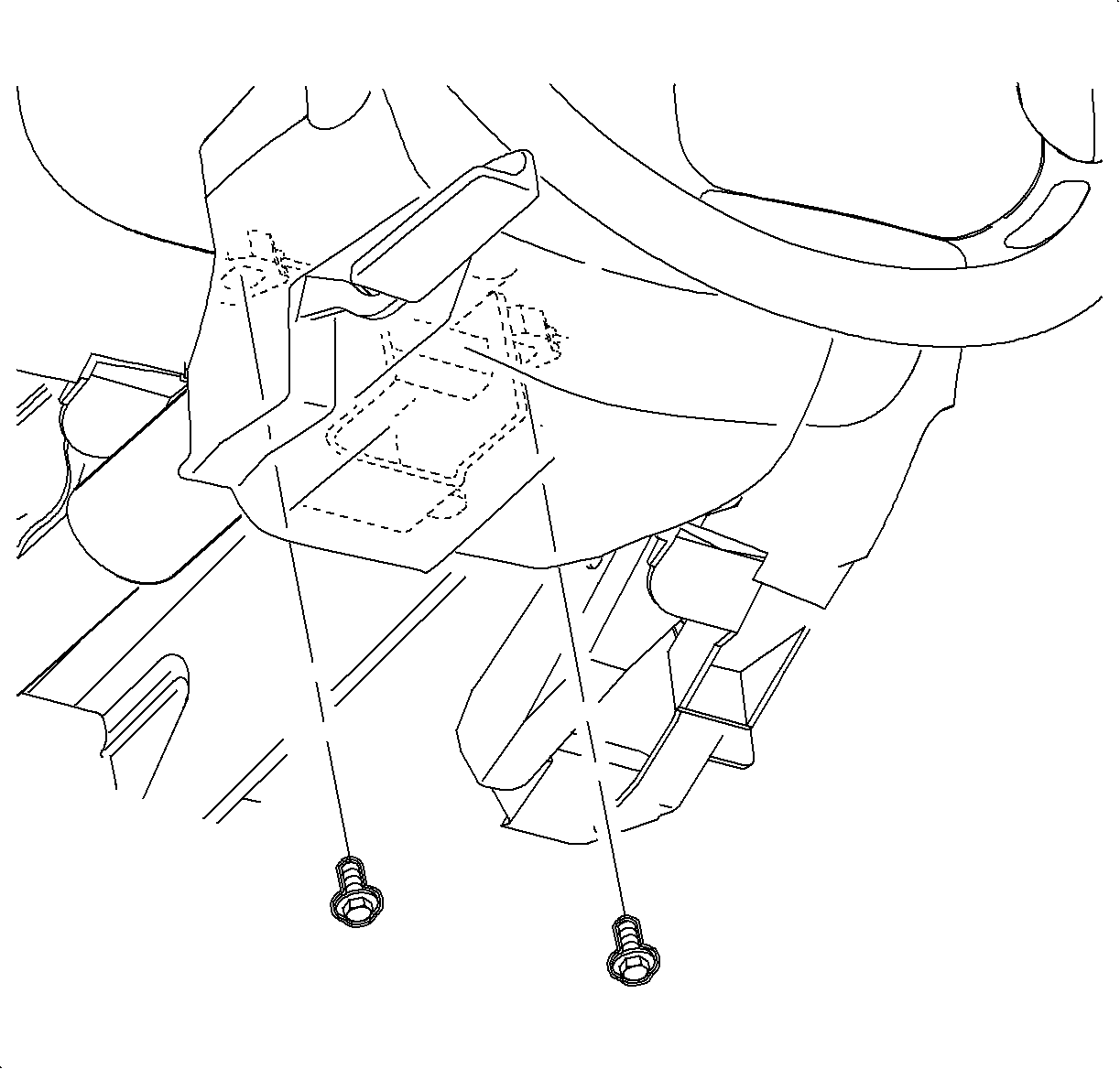
- Remove the steering column bolts and lower the column on the front seat.
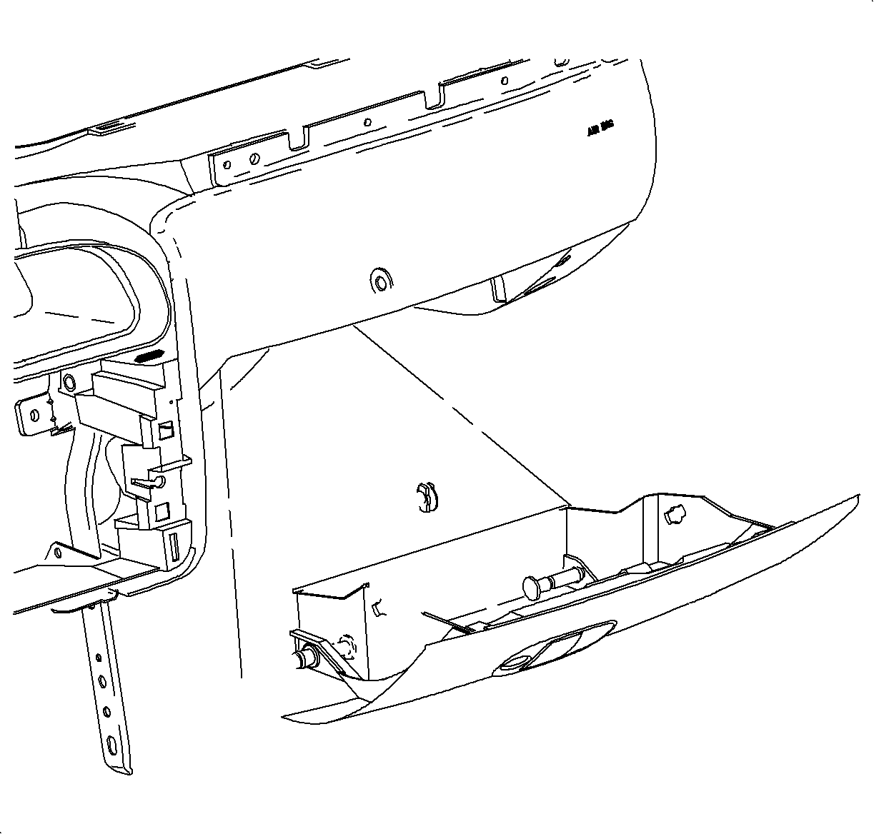
- Remove the I/P compartment:
| 37.1. | Open the I/P compartment door. |
| 37.2. | Turn the right and left I/P compartment door stop assemblies to release
the door and the compartment assembly from the I/P retainer assembly. |
| | Important: Lower I/P door pins are on the right and left outside edges at the base of the
compartment.
|
| 37.3. | Push the lower I/P door pins from the outside of the door to inside the I/P
compartment. |
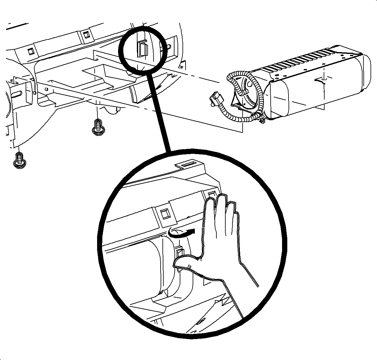
- Remove the screws
and the passenger side inflatable restraint cover.
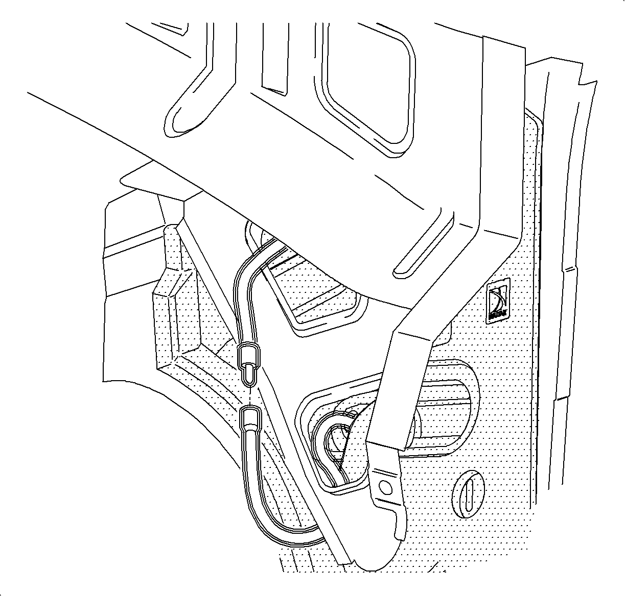
- Disengage the antenna lead.
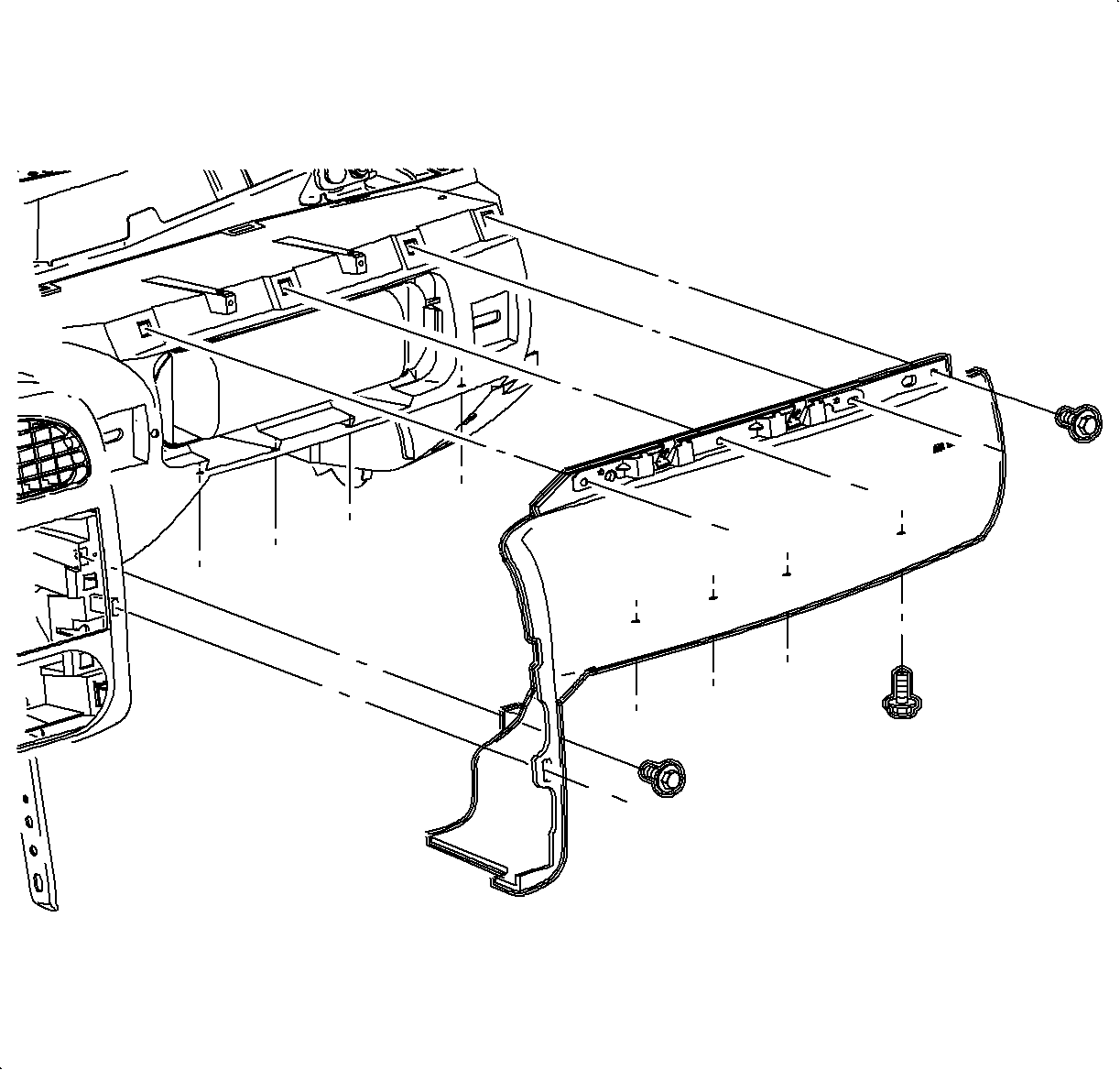
- Remove the H-brace to the front floor bracket assembly bolts.
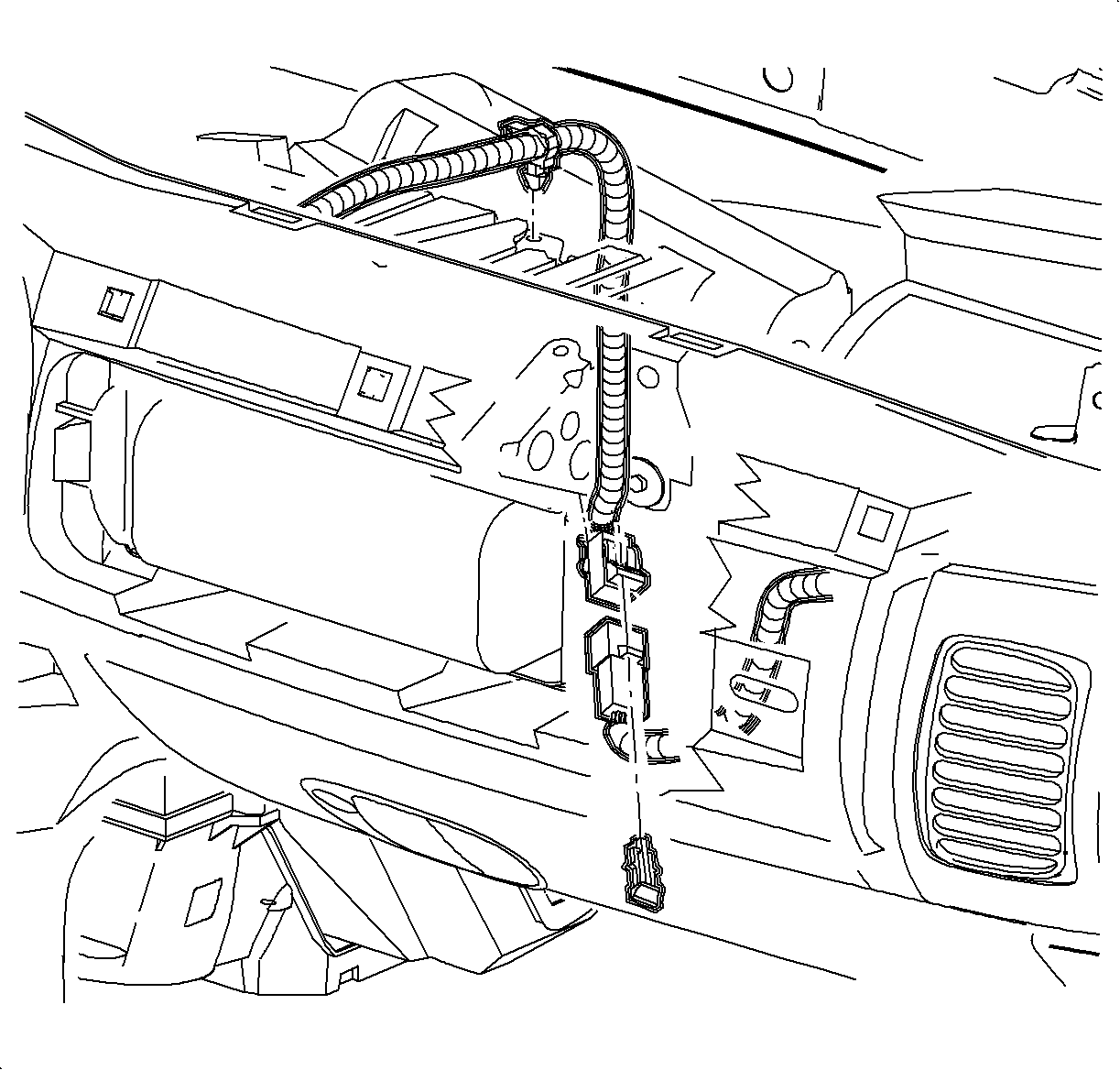
- Remove the passenger side inflator module.
| 41.1. | Unclip the plastic retainer and lift the inflator module harness out of
the energy absorber. |
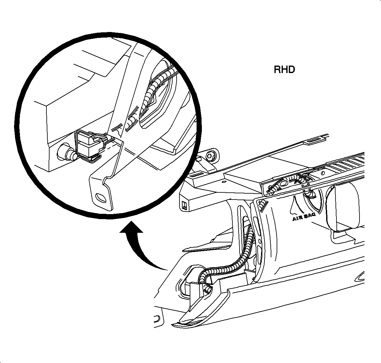
| 41.2. | For RHD domestic
vehicles: |
Remove the clip from the retaining assembly.

| 41.3. | Remove the screws located underneath the inflator module. |
| 41.4. | Pry the retaining tabs outward that retain the inflator module to the
I/P retainer assembly. |
| 41.5. | Remove the inflator module from the opening. |
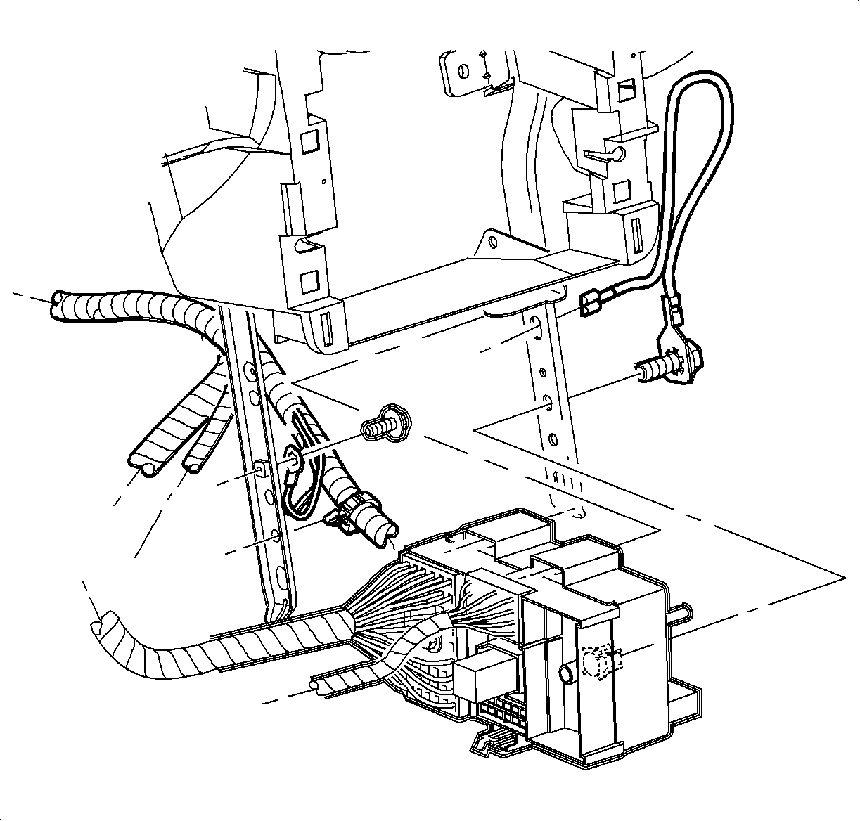
- Remove the I/P harness plastic retainer from the H-brace
- Remove the screw and the ground wires from the H-brace.
- Remove the radio ground strap from the H-brace.
- Remove the junction block.
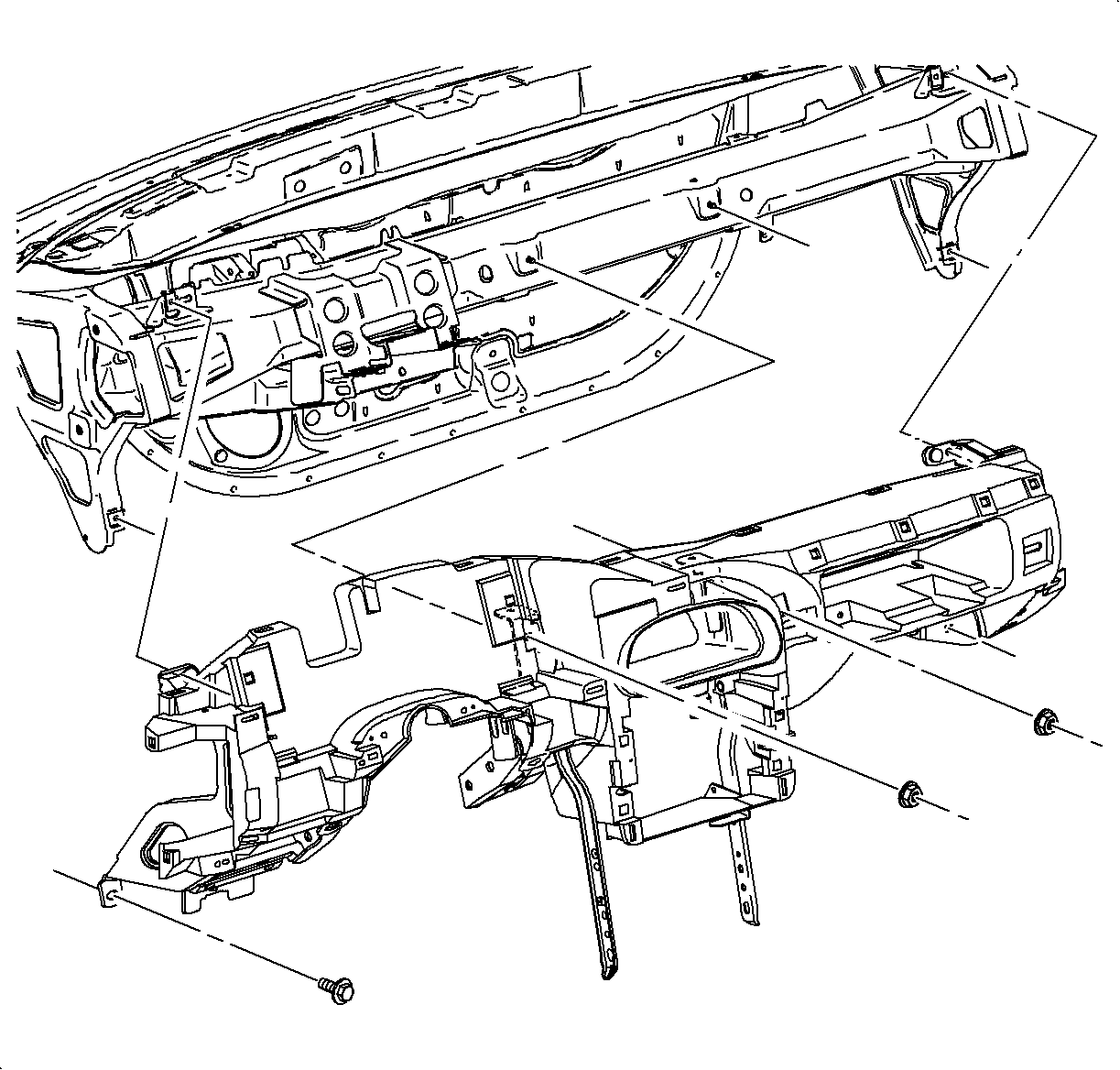
Important: Use the illustration to determine the fastener location and the direction of
removal.
- Remove the I/P screws and nuts.
Notice: Put I/P retainer assembly on a clean surface so that the assembly surface does
not become damaged.
- Remove the I/P retainer assembly from the vehicle.
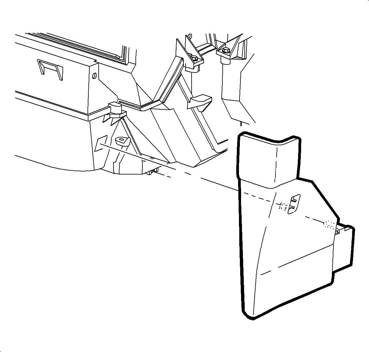
- Remove the I/P lower closeout panel by pulling out at the top edge, and then
rotating the top downward.
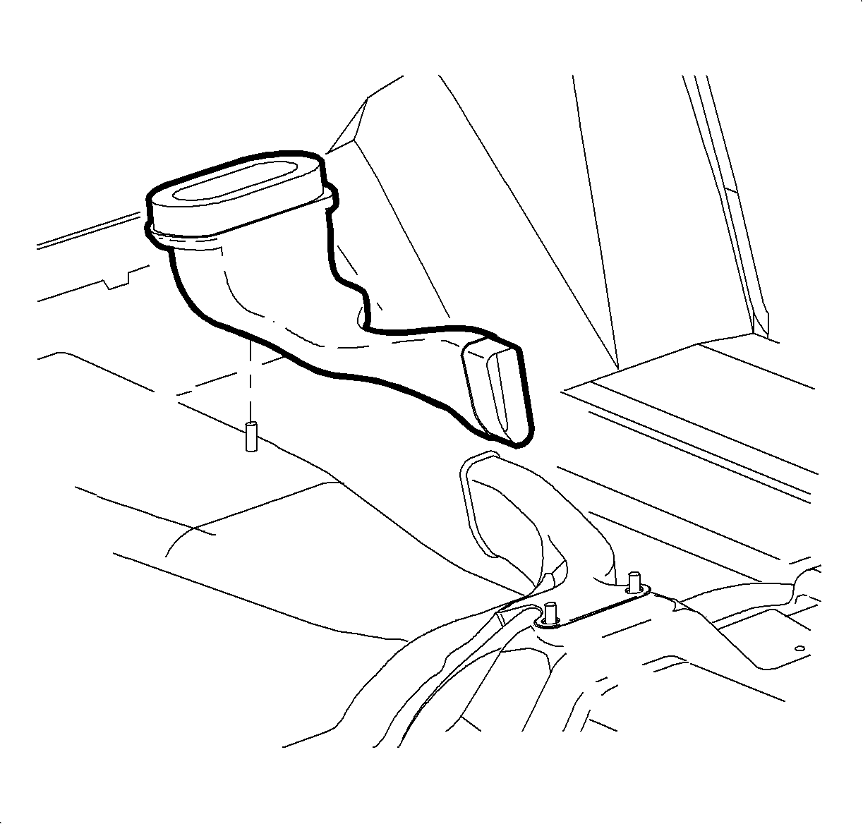
- For Sedans and Wagons, remove the lower heater duct. Refer to
Auxiliary Heater Core Replacement
.
Notice: Be careful not to damage foam seal.
- Lift the rear floor heater duct off of the mounting bolt and remove.
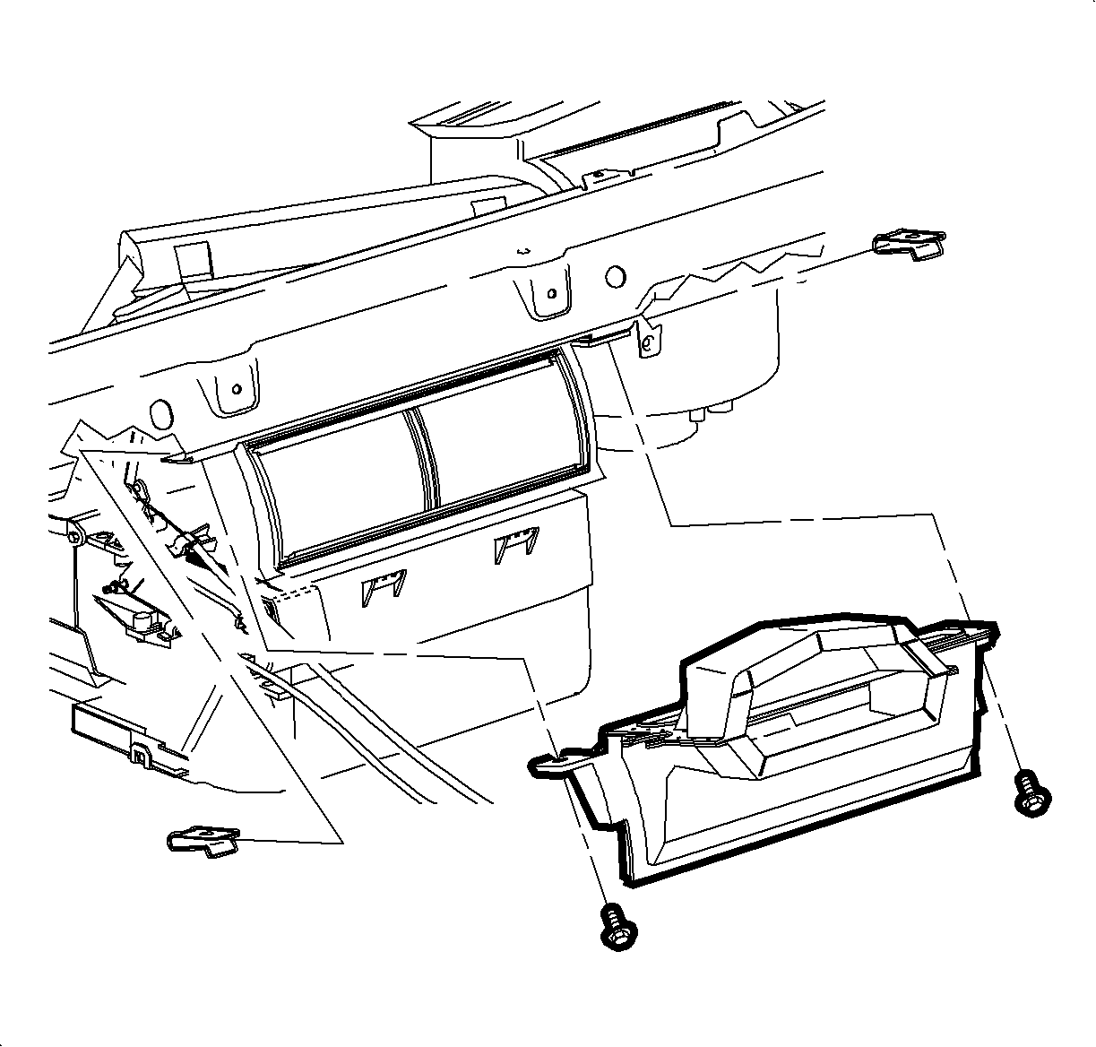
- Remove the screws and center air outlet duct.
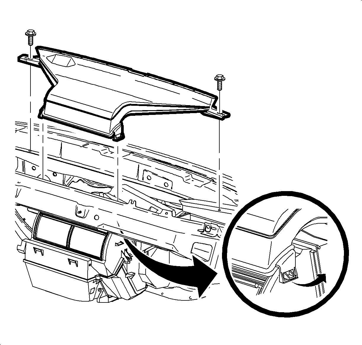
- Remove the screws and unsnap the windshield defroster nozzle from the mode valve
assembly.
Important: For SC1 and SC2 vehicles, leave the defroster nozzle in place after disconnecting.
The nozzle cannot be removed because of the windshield rake angle.
- Remove the defroster nozzle by rotating the front of the nozzle up and away
from the windshield.
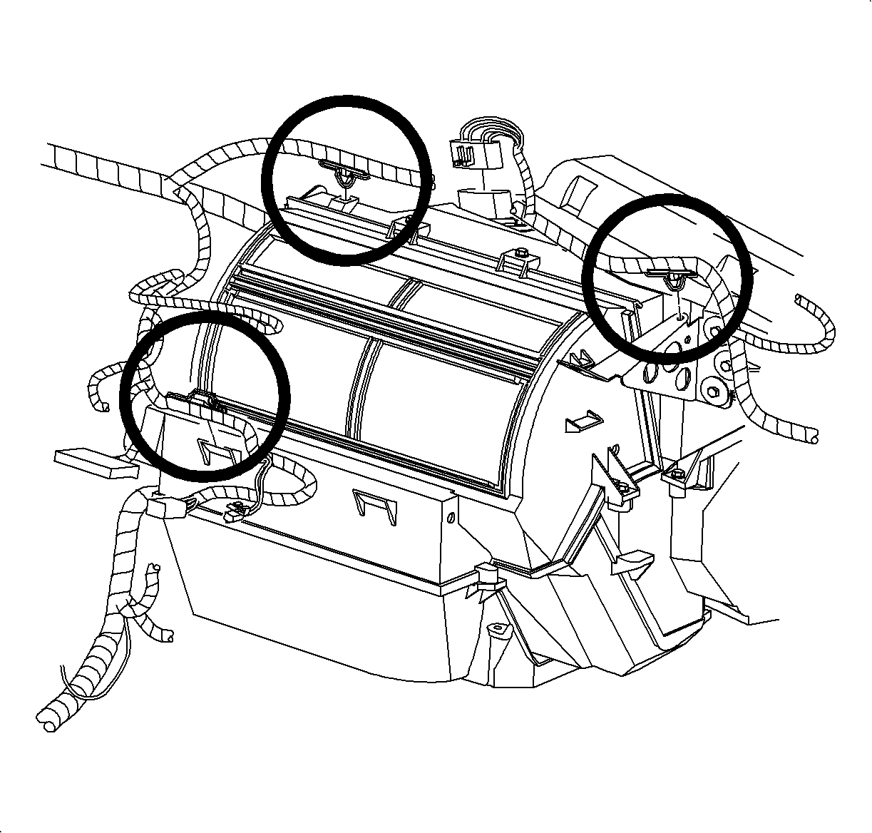
- Disconnect the blower motor resistor connector.
- Remove the wire harness and hold down the clips from the HVAC module.
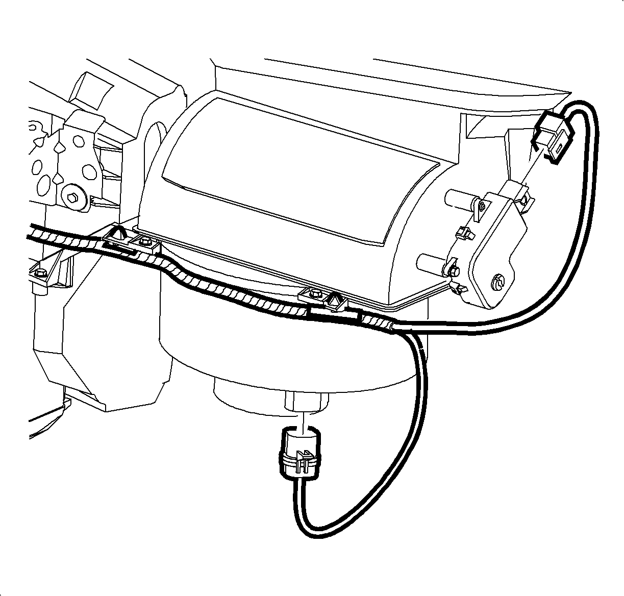
- Disconnect the blower motor and recirc motor electrical connectors.
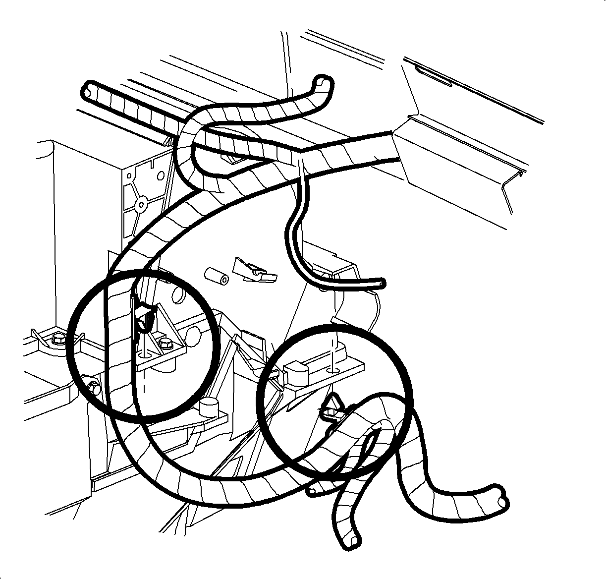
- Remove the wiring harness and hold down the clips from the HVAC module.
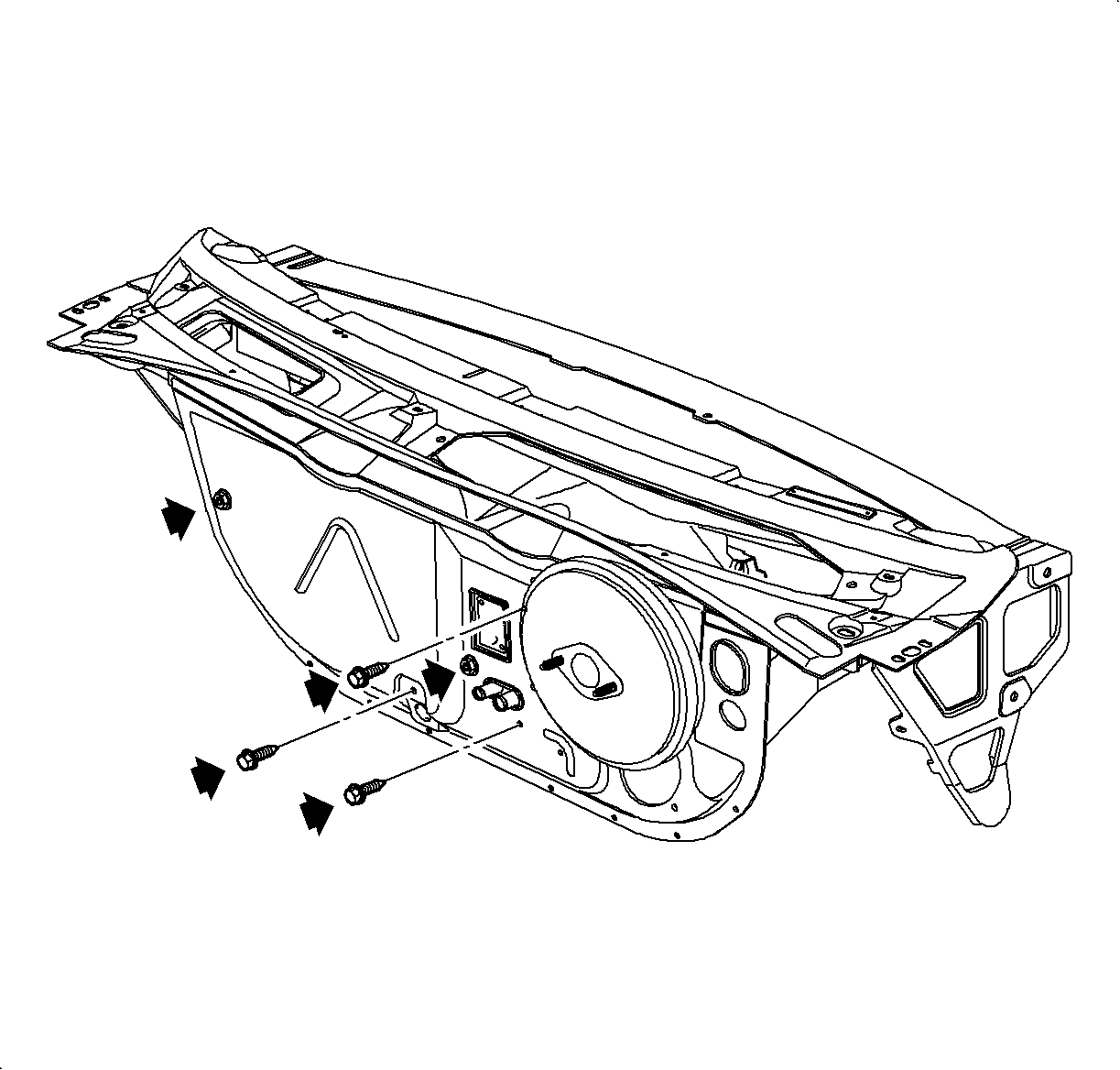
- Remove the fuel vapor line and the clip from the HVAC module stud to gain access
to the nut.
Important: Lower fasteners may be easier to access by raising the vehicle.
- Remove the 3 screws and 2 nuts holding the HVAC module to the
cowl.
Fastener Locations:
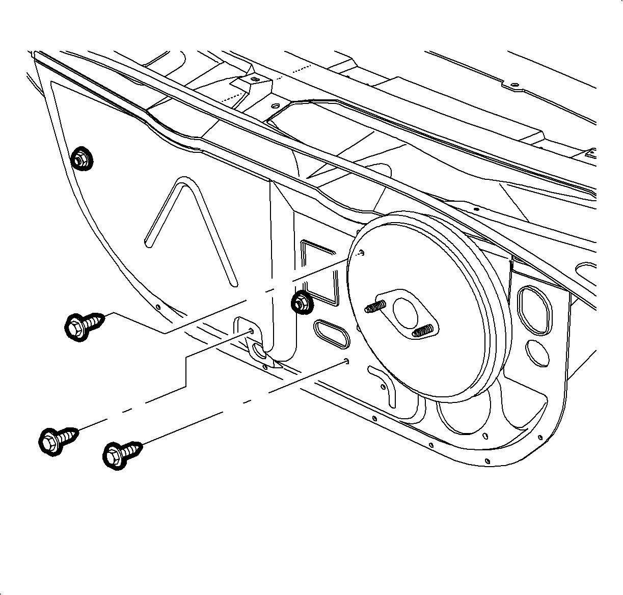
| • | Screw to the upper right side of the TXV. |
| • | Screw below the heater core outlet pipe. |
| • | Screw just above the HVAC module case drain. |
| • | Nut to the upper left of the heater core inlet pipe, below the TXV. |
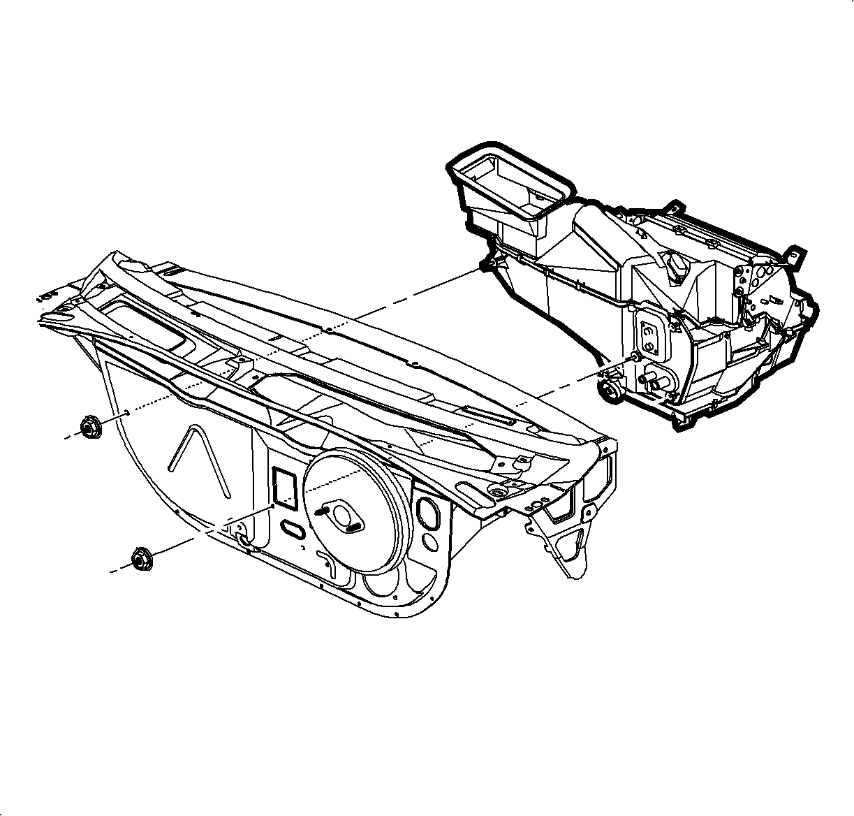
- Remove the HVAC module from the vehicle. Remove the nut on the left side of
the cowl.
Installation Procedure
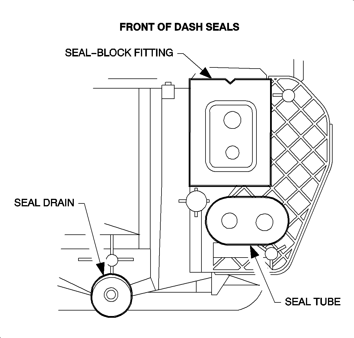
- Install the new
cowl panel seals on the heater core pipes, the case drain, and the evaporator block.
Notice: Refer to Fastener Notice in the Preface section.
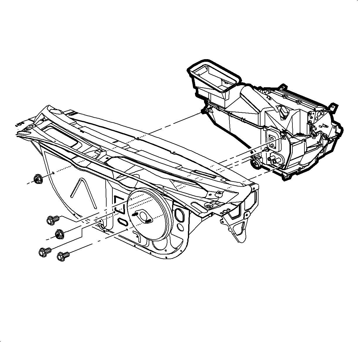
- Install the HVAC module through the cowl. Install the screws and nuts.
Tighten
Tighten the clutch coil-to-compressor screws to 5 N·m (44 lb in).
- Install the fuel vapor line and the clip to the stud below the TXV.

- Connect the blower motor and the recirc motor electrical connectors.
- Install the wire harness hold down clips on the HVAC module.

- Connect the blower motor resistor electrical connector.
- Install the wire harness hold down clips on the HVAC module.
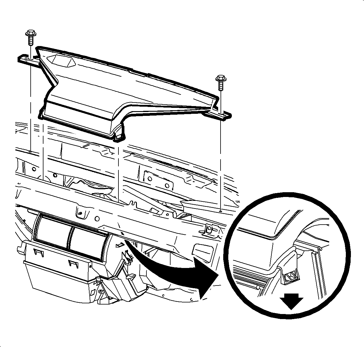
- Rotate the windshield defroster nozzle onto the mode valve assembly and install
the screws. Make sure the duct is snapped on both sides of the HVAC module.
Tighten
Tighten the windshield defroster nozzle to 2.2 N·m (20 lb in).

Important: Make sure that the plastic right mounting tab is between the knee beam and the
mounting bracket.
- Install the center air outlet duct and screws.
Tighten
Tighten the center air outlet duct to 10 N·m (89 lb in).

- For SL and SW only, install the rear floor heater duct and place on the mounting
stud.
Notice: Be careful not to damage foam seal.
- Install the lower heater duct.

- Install the I/P retainer assembly.
- Install the I/P retainer assembly to the dash panel assembly bolts and
nuts, but do not tighten the bolts and nuts.

- Install the junction block to the H-brace.
- Install the ground wires with a screw to the H-brace.
Tighten
Tighten the ground wires-to-H-brace to 2.2 N·m (20 lb in).
- Install the radio ground strap and screw through the H-brace to the junction
block.
Tighten
Tighten the radio ground strap-to-H-brace to 2.2 N·m (20 lb in).
- Return the I/P harness plastic retainer to the H-brace.

- Install the H-brace bolts to the front floor bracket.
Tighten
Tighten the H-brace-to-front floor bracket to 25 N·m (19 lb ft).

Important: Do not connect the passenger side inflator restraint harness connectors at this
time.
- Route the passenger side inflator module harness through the retainer assembly.
Close the harness retainer assembly clip.

- For RHD domestic vehicles:
Route the harness through the retainer assembly and clip the electrical connector
to the retainer assembly.

- Position the inflator module in the opening in the I/P retainer assembly.
- Install the inflator module ensuring the retaining tabs are engaged to
the I/P reinforcement assembly.
- Install the 2 inflator module bolts and tighten.
Tighten
Tighten the inflator module bolts to 10 N·m (89 lb in).

- Tighten the I/P retainer assembly bolts and nuts.
Tighten
Tighten the I/P retainer assembly fasteners to 10 N·m (89 lb in).

- Connect the antenna cable and secure to the lower right side of the instrument
panel retainer assembly.

- Install the inflator
module cover.
Tighten
Tighten the inflator module cover fasteners to 2.2 N·m (20 lb in).

- Install the I/P compartment:
| 26.1. | Position the I/P compartment door assembly to the retainer assembly. |
| 26.2. | Install the I/P compartment door pins into the instrument panel retainer
assembly. |
| 26.3. | Lift the I/P compartment enough to install the I/P compartment door stop
assemblies. |
| 26.4. | Close the I/P compartment door. |

- Raise the steering column into position.
- Install and tighten the bolts.
Tighten
Tighten the steering column bolts to 35 N·m (26 lb ft).
Cable identification:

| • | Temperature cable - white |
Important: Make sure the wiring harnesses do not interfere with the control lever movement.
- Install the HVAC controller:
| 29.1. | Install the mode valve cable onto the mode valve pin. |
| 29.2. | Snap the slot on the cable into the HVAC controller base. |
| 29.3. | Repeat the steps for the temperature cable. |

| 29.4. | Install the blower switch connector. |
| 29.5. | Install the HVAC controller harness. |
| 29.6. | Install and tighten the screws. |
Tighten
Tighten the HVAC controller-to-I/P retainer to 2.5 N·m (22 lb in).

- Install the radio:
| 30.1. | Connect the radio ground strap spade terminal. |
| 30.2. | Connect the electrical connectors. |
| 30.3. | Connect the antenna lead. |
| 30.4. | Install the radio by sliding it into the guides on the instrument panel. |
| 30.5. | Install and tighten the screws. |
Tighten
Tighten the radio-to-I/P retainer to 2.5 N·m (22 lb in).

- Install the I/P cluster:
| 31.1. | Place the tabs on the bottom of the I/P cluster into the retainer assembly. |
| 31.2. | Install the screws. |
| 31.3. | Connect the electrical connector to the instrument panel cluster. |
Tighten
Tighten the I/P cluster retaining screws to 3 N·m (27 lb in).

- Install the I/P cluster bezel:
| 32.1. | Pull the dimmer/traction control switch harness through the I/P cluster
bezel opening. |
| 32.2. | Position the I/P cluster bezel by lining up the clip location. |
| 32.3. | Snap the I/P cluster bezel in place by pushing at the clip locations. |

- Position the upper steering column shroud.
- Position the lower steering column shroud and install the screws.
Tighten
Tighten the steering column shroud fasteners to 1.5 N·m (13 lb in).
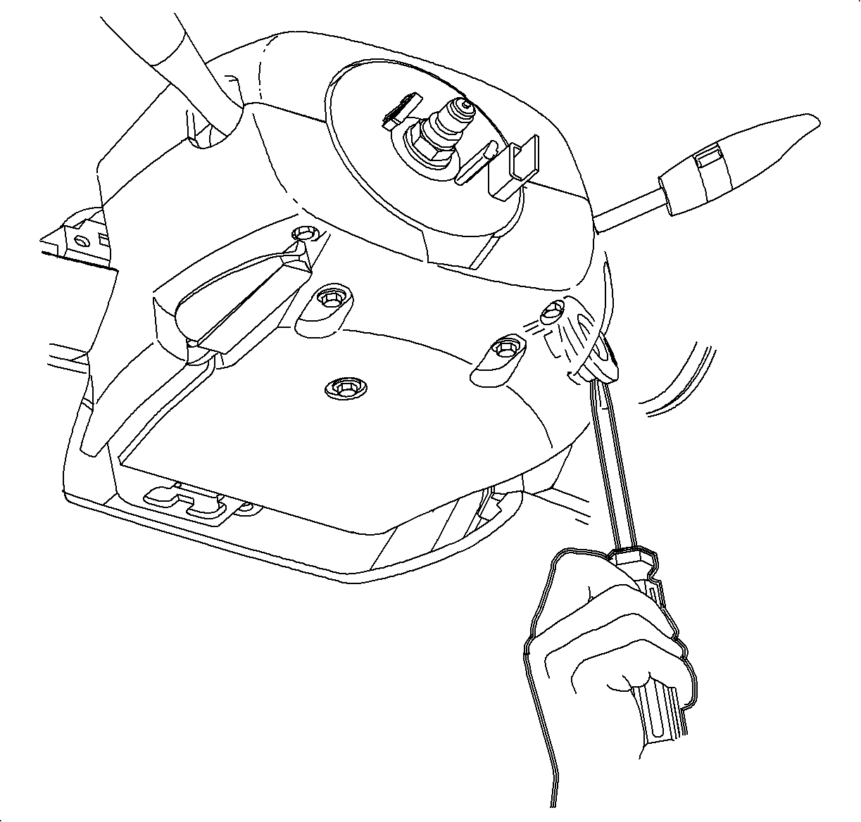
- Install the ignition bezel:
| 35.1. | Align the peg of the ignition bezel with the cut out in the lower shroud. |

- Connect the traction control and the dimmer switch wiring harness, if equipped.
- Install traction control/dimmer switch.

- Connect the left and the right door jamb switch connectors.
Important: Ensure that the endcap bottom portions are inside of the filler panel and the
glovebox assemblies.
- Install the left and right endcap assembly:
| 39.1. | Maneuver the assemblies past the inner I/P retainer assembly and weatherstrips. |
| 39.2. | Snap the clips into the I/P retainer assembly locations. |
| 39.3. | Install the screws. |
Tighten
Tighten the I/P endcap retaining screws to 2.5 N·m (22 lb in).

- Install the data link connector.
- Route the hood release cable through the I/P and then install the cable
to the lever.
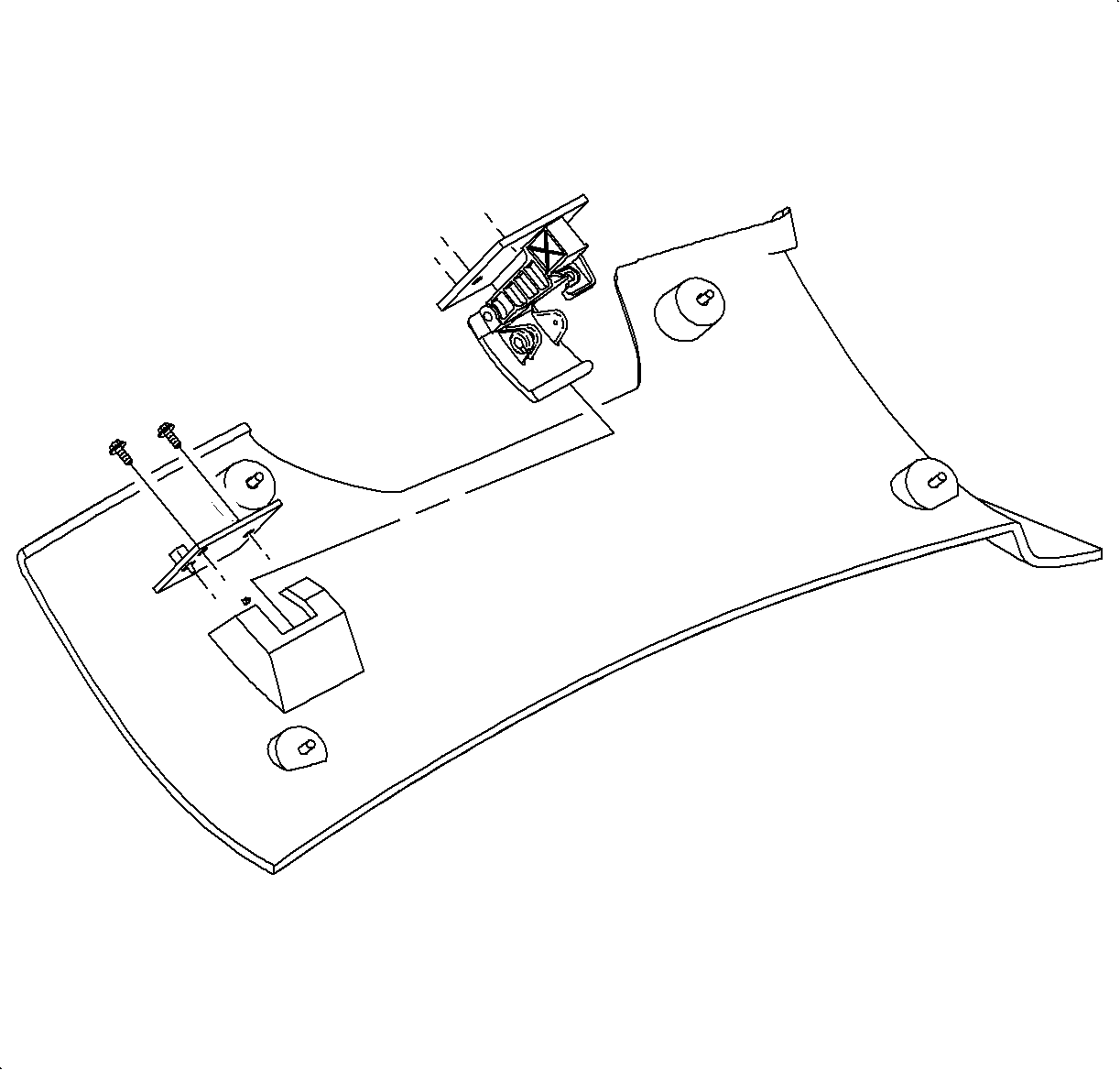
- For RHD domestic vehicles:
Install the hood release handle assembly. Install the hood release handle screws.

- Install the steering column filler panel.
Tighten
Tighten the steering column filler panel fasteners to 2.5 N·m (22 lb in).

Notice: Be careful not to damage the VIN plate when removing or replacing the upper
trim panel.
Important: Be sure the upper trim panel seal is correctly seated on the forward edge before
installing the upper trim panel.
- Install the upper trim panel.
| 43.1. | Ensure the hook-and-loop fasteners on the upper trim panel are correctly
inserted. |
| 43.2. | Position the upper trim panel on the retainer assembly. |
| 43.3. | Align the tabs on the sides of the upper trim panel with the openings
in the windshield garnish molding. |
| 43.4. | Align the clips and the clip location. |
| 43.5. | Firmly snap in the clips at the clip locations. |
| 43.6. | Install the screws on the underside of the upper trim panel on the passenger's
side of the vehicle. |
Tighten
Tighten the I/P upper trim panel fastener to 6 N·m (53 lb in).

- Install the console:
| 44.1. | Apply the park brake. |
| 44.2. | Adjust the front seats to the most rearward position. |
| 44.3. | Recline the driver's and passenger's seatbacks as far down as possible. |
| 44.4. | Select neutral for the transaxle gear, on automatic transaxles. |
| 44.5. | Hold the front end of the console down and the rear end up. |
| 44.6. | Position all the harnesses so they can be accessed. |
| 44.7. | Maneuver the console over the gear selector lever and past the brake lever. |
| 44.8. | Connect the power outlet electrical connector. |

| 44.9. | On automatic transaxle equipped vehicles, remove the tape from the gear selector. |
| 44.10. | Install the screws at the rear of the console. |
Tighten
Tighten the rear console screws to 2.5 N·m (22 lb in).

| 44.11. | Install and tighten the front console screws. |
Tighten
Tighten the front console screws to 2.5 N·m (22 lb in).

| 44.12. | Install the left and right extension panels by inserting the hinges into the
console. |
| 44.13. | Rotate the closed, and push in at the dual lock locations. |

- Connect the window switch assembly connector, if equipped.
- Install the window switch assembly or the storage tray, depending on the
equipment.
Caution: Refer to Vehicle Lifting Caution in the Preface section.
- Raise the vehicle. Refer to
Lifting and Jacking the Vehicle
in General Information.
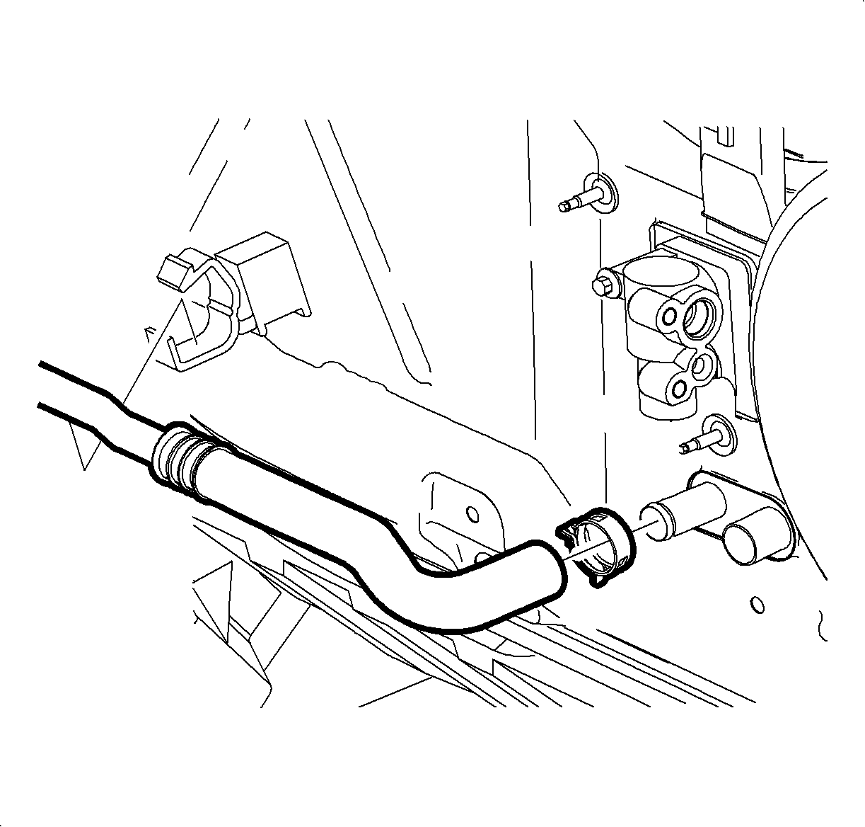
Important: Be careful not to push the hoses onto the heater core so far that the foam seal
is unseated.
- Install the hose and the clamp on the heater core outlet. Position the clamp
at a 7-8 o'clock position.
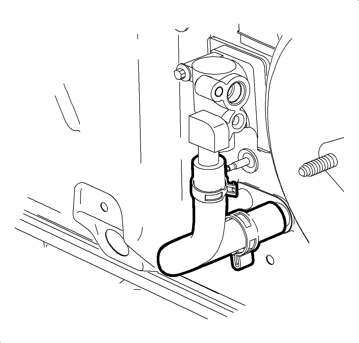
- Install the hose and the clamp on the heater core inlet. Position the clamp
at a 6 o'clock position.
- Lower the vehicle.
Notice: Use only Polyalkylene Glycol Synthetic Refrigerant Oil (PAG) for internal
circulation through the R-134a A/C system and only 525 viscosity mineral oil
on fitting threads and O-rings. If lubricants other than those specified are
used, compressor failure and/or fitting seizure may result.
- Remove the protective covers. Lubricate with R-12 Refrigerant
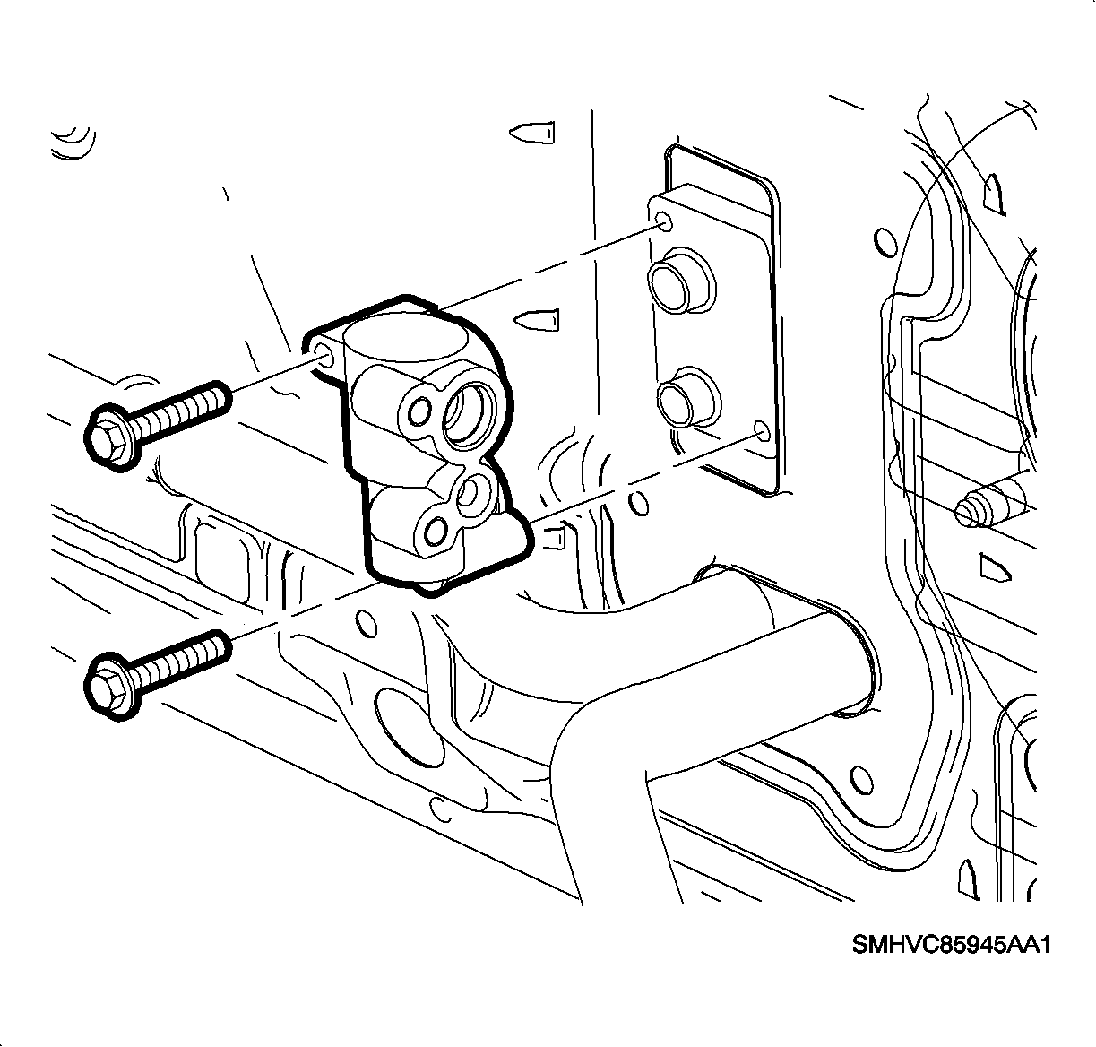
oil (mineral) and install the new O-rings on the evaporator pipes.
- Install the thermal expansion valve (TXV) on the evaporator.
Tighten
Tighten the receiver-dehydrator mounting nut to 10 N·m (89 lb in).
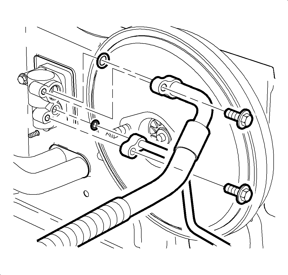
- Lubricate the O-rings with R-12 Refrigerant oil (mineral) and install
the new O-rings on the suction hose and the liquid line.
- Install the liquid line on the TXV.
Tighten
Tighten the liquid line-to-thermal expansion valve to 25 N·m (19 lb ft).
- Install the suction hose on the TXV.
Tighten
Tighten the suction hose-to-compressor to 25 N·m (19 lb ft).

- Install the air cleaner housing cover and the air induction hose.
- Fill and pressure test the cooling system.
- Evacuate, charge, and leak test the A/C system. Perform the A/C Performance
Test.
- Connect the negative battery cable.
Tighten
Tighten the negative battery cable to 17 N·m (13 lb ft).
- Set the clock to the proper time, if equipped.
- Enable the SIR system. Refer to
Enabling the SIR System
in SIR
- Reset the radio stations.
HVAC Module Assembly Replacement RHD Domestic Only
Removal Procedure

- Disable the SIR system. Refer to
Disabling the SIR System
in SIR
- Record the pre-set radio stations.
Caution: Refer to Battery Disconnect Caution in the Preface section.
- Disconnect the negative battery cable.
- Recover the refrigerant using an approved refrigerant recovery system.
- Remove the air cleaner housing cover and the air induction hose at the
intake manifold.

- Remove the suction hose and the liquid line from the thermal expansion valve
(TXV).
Notice: Place protective covers over A/C hoses, lines, TXV, and HVAC module to prevent
contamination of A/C system.

- Remove the coolant
reservoir cap.
- Drain the cooling system.

- Remove the heater inlet hose from the engine outlet and blow the remainder of
coolant out of the heater core with an air hose in order to prevent coolant from
spilling on the vehicle interior when removing the HVAC module.
- Install the heater inlet hose on the engine outlet and position the clamp
at the 4 o'clock position as viewed from the left side of the vehicle.
Caution: Refer to Vehicle Lifting Caution in the Preface section.

- Raise the vehicle.
Refer to
Lifting and Jacking the Vehicle
in General Information.
- Move the clamps up the heater core inlet and outlet hoses.

- Remove the hoses from the heater core.
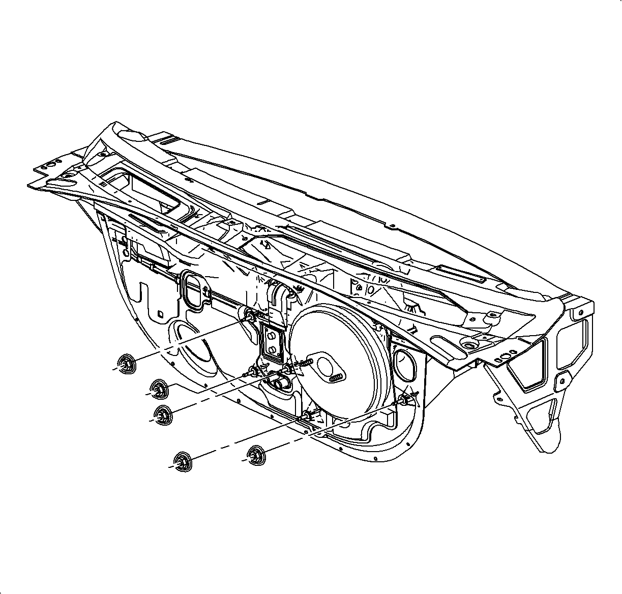
- Remove the 4 nuts holding the lower HVAC module and blower unit to the
cowl.
Fastener locations:
| • | Left upper side of the TXV. |
| • | Lower right side of the TXV. |
| • | Left of the module drain. |
| • | Lower left side of the brake booster. |
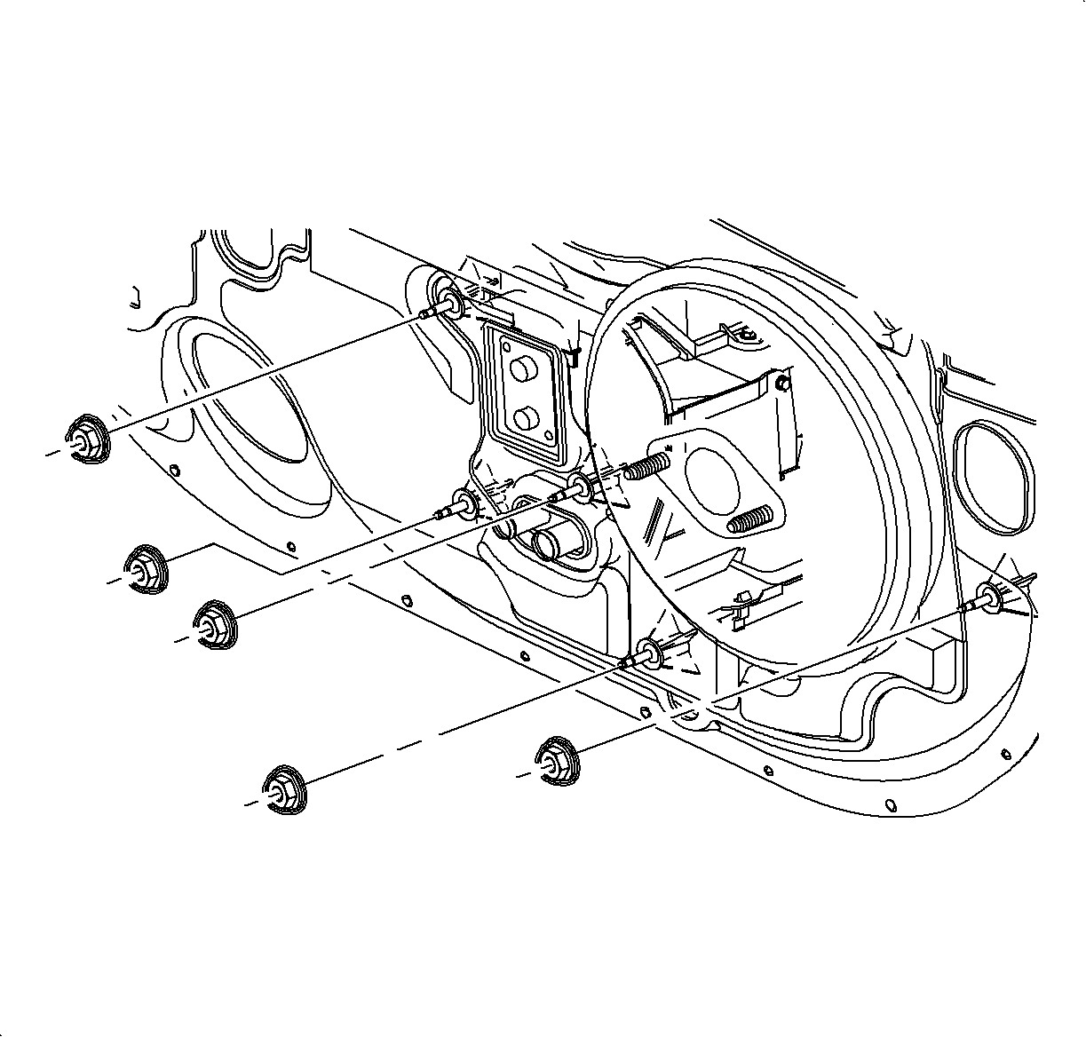
- Lower the vehicle.
- Remove the nut holding the blower unit to the cowl at the right center
of the brake booster.

- Apply the parking brake lever.
- Remove the window/mirror switch, if equipped.
| 18.1. | Using a small flat blade screwdriver, carefully lift the switch. |

| 18.3. | Disconnect the electrical connectors by locating the retention tabs and
disengaging the connections. |

- Remove the console:
| 19.1. | Select neutral for the transaxle gear, on automatic transaxles. |
| 19.2. | Adjust the front seats to the most forward position. |
| 19.3. | Remove the rear console screws. |

| 19.4. | Adjust the front seats to the most rearward position. |
| 19.5. | Remove the left and right lower trim panel extensions by pulling outward
at the dual lock locations. |
| 19.6. | Rotate the panels outward to disengage the hinges from the console. |

| 19.7. | Remove the front console screws. |
| 19.8. | Move the console rearward. |
| 19.9. | Disengage the retaining tabs and disconnect the power outlet connector. |

| 19.10. | On automatic equipped vehicles, press and tape the gear selector button in to
the clear shifter opening. |
| 19.11. | Maneuver the console beyond the gear selector and parking brake by lifting
the rear of the console. |
| 19.12. | Remove the console from the vehicle. |
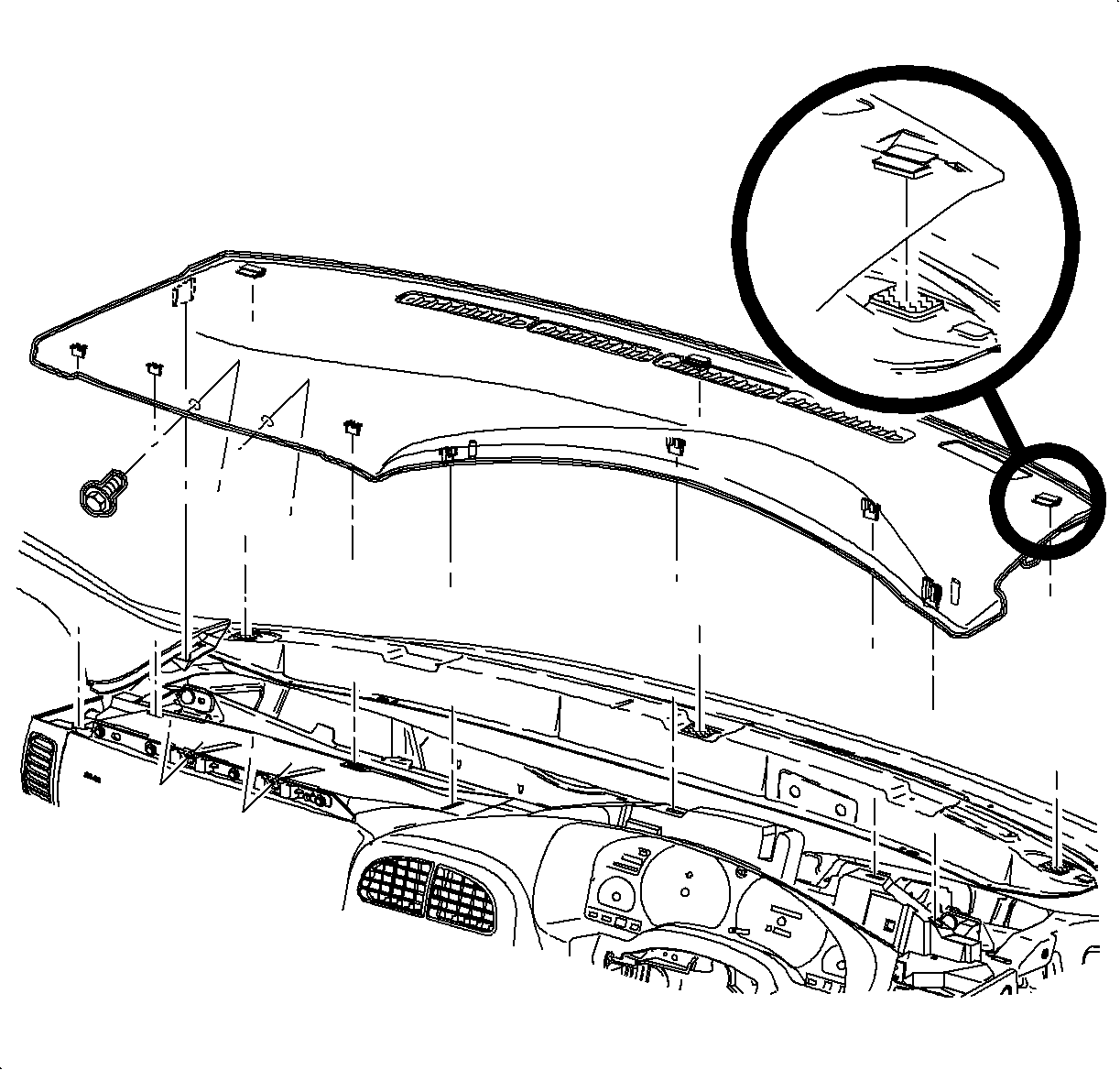
- Remove the I/P top cover:
| 20.1. | Remove the screws located under the upper trim panel on the passenger's
side of the vehicle. |
| | Notice: Be careful not to damage the VIN plate when removing or replacing the upper
trim panel.
|
| 20.2. | Disengage the clips at the locations by grasping the edges of
the instrument panel upper trim and lifting up. |
| 20.3. | Disengage the hook-and-loop attachments at the rear of the instrument
panel upper trim by reaching under the panel and lifting straight up. |
| 20.4. | Raise the instrument panel upper trim enough to clear the VIN plate. |
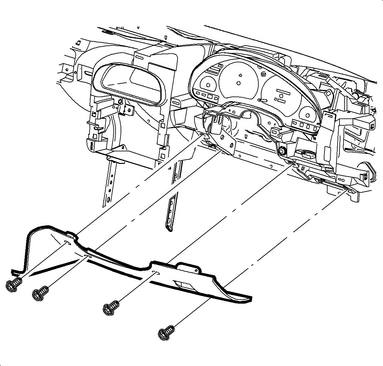
- Remove the steering column filler panel screws.
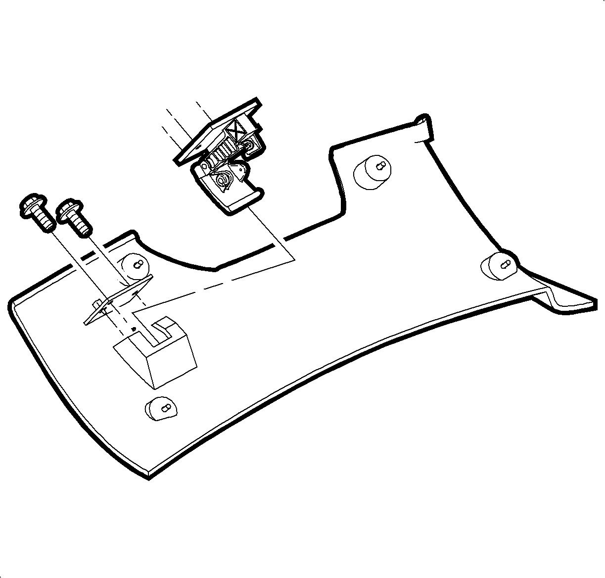
- Remove the hood release handle assembly.
- Remove the steering column filler panel.
Notice: Do not remove weatherstrips. Adhesion will be lost if removed.
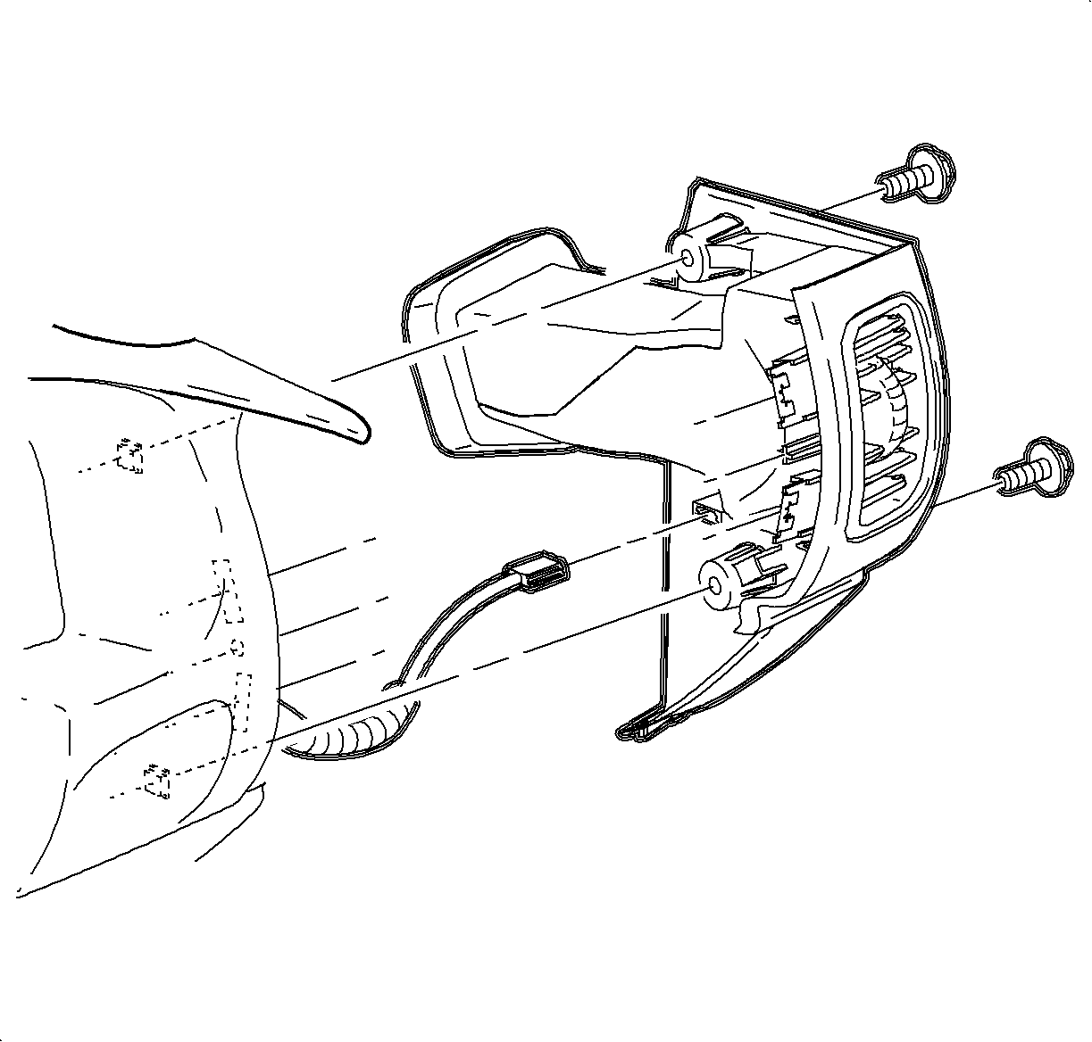
- Remove the right and left endcap assemblies:
| 24.2. | Carefully disengage the clips at the I/P retainer assembly locations.
Use of a blunt tool will aid in disengaging the clips. |
| 24.3. | Maneuver the assemblies past the inner I/P retainer assembly and weatherstrips. |
- Remove the wiring harness from the door jamb switch.

- Gently pry the edges of the ignition lock bezel with a blunt tool and separate
from the lower shroud.

- Remove the screws and the lower steering column shroud.
- Lower the steering column by pushing down on the steering column adjusting
handle.
- Lift and remove the upper shroud from the steering column.
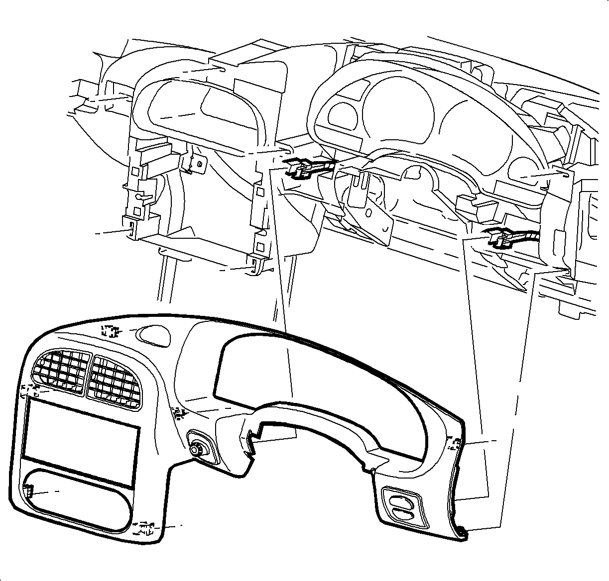
- Remove the I/P cluster bezel:
Disengage the clips from the retainer assembly by grasping the edges of the
bezel near the clip locations and pull outward.
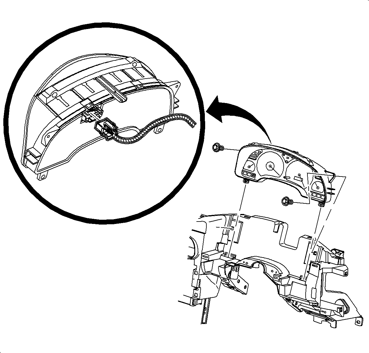
- Remove the I/P cluster:
| 31.2. | Disconnect the electrical connector from the I/P cluster by squeezing
the tabs on each side of the connector. |

- Remove the radio:
| 32.1. | Remove the radio screws. |
| 32.2. | Pull the radio out slightly to access the rear. |
| 32.3. | Disconnect the electrical connector, the antenna, and the ground strap
connector. |

- Remove the HVAC Controller:
| 33.2. | Disconnect the HVAC blower switch connector. |
| 33.3. | Disconnect the HVAC control head connector. |

| 33.4. | Remove the temperature cable by squeezing the lock tabs together while pulling
the coiled end cable straight up beyond the retaining tabs. |
| 33.5. | Remove the mode cable by squeezing the lock tabs together while pulling
the coiled end cable straight up beyond the retaining tabs. |
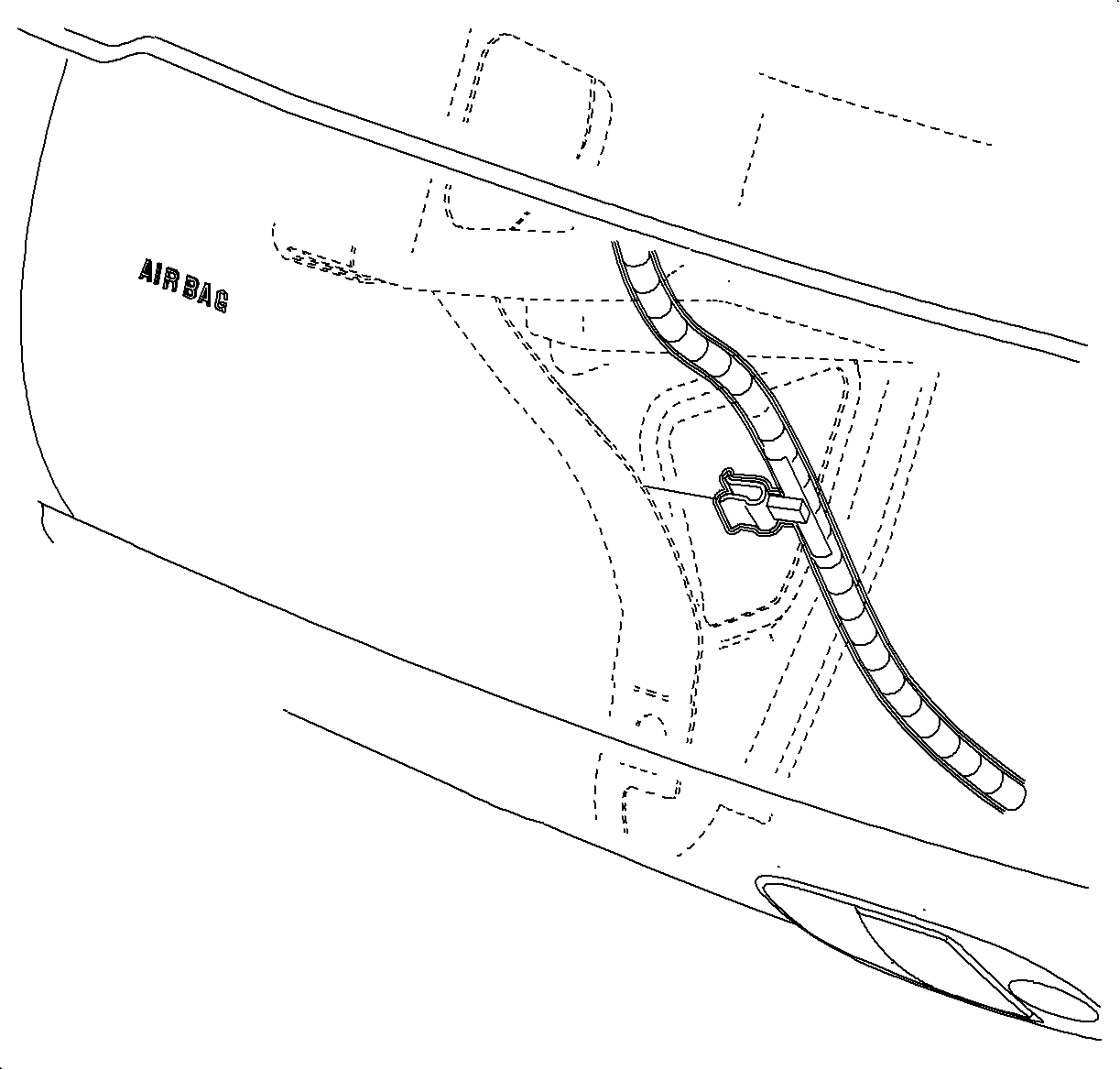
- Disengage the door jamb switch wiring harness retainer (metal clip). Remove
the left and right harnesses from the I/P retainer assembly.
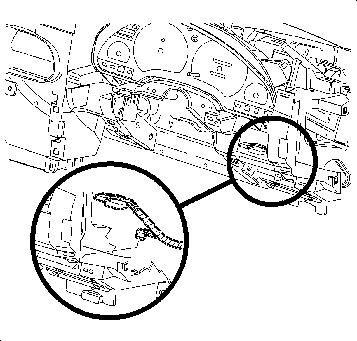
- Disengage the dimmer/traction control switch wiring harness from the retainer
assembly.

- Remove the steering column bolts and lower the column on the front seat.
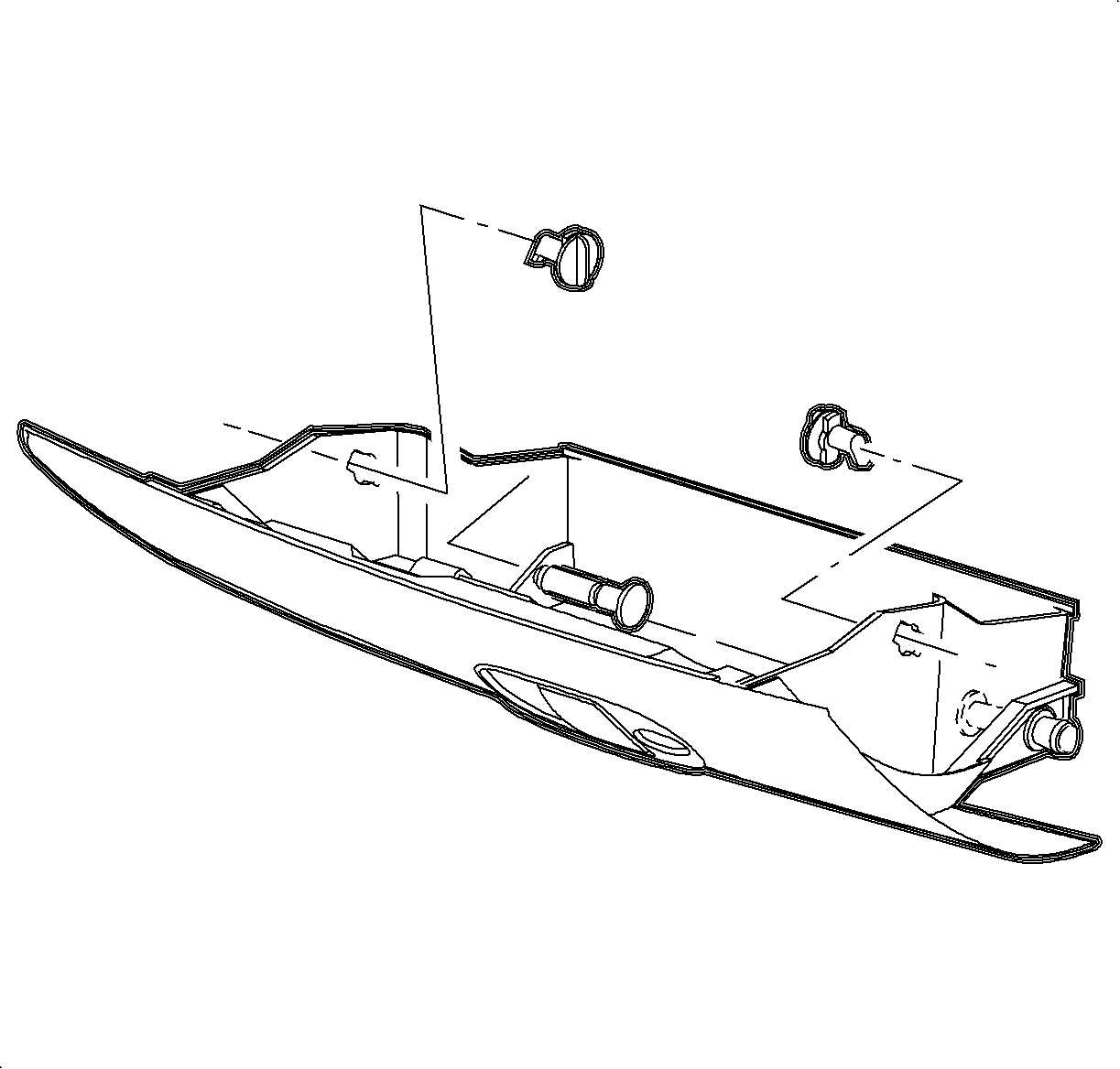
- Remove the I/P compartment:
| 37.1. | Open the I/P compartment door. |
| 37.2. | Turn the right and left I/P compartment door stop assemblies to release
the door and compartment assembly from the I/P retainer assembly. |
| | Important: The lower I/P door pins are on the right and left outside edges at the base
of the compartment.
|
| 37.3. | Push the lower I/P door pins from the outside of the door to inside the I/P
compartment. |
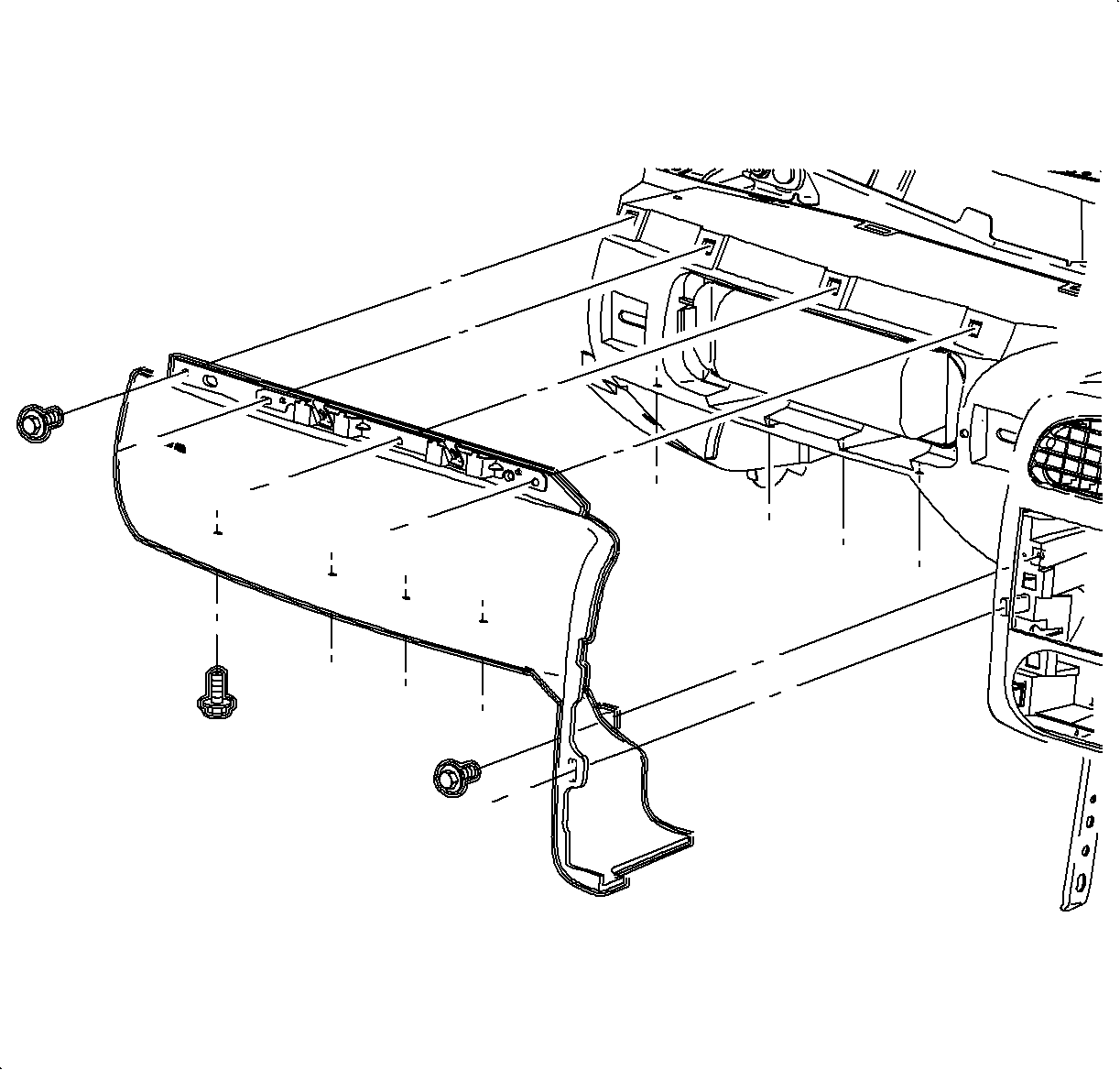
- Remove the screws and the passenger's side inflatable restraint cover.

- Remove the H-brace to the front floor bracket assembly bolts.
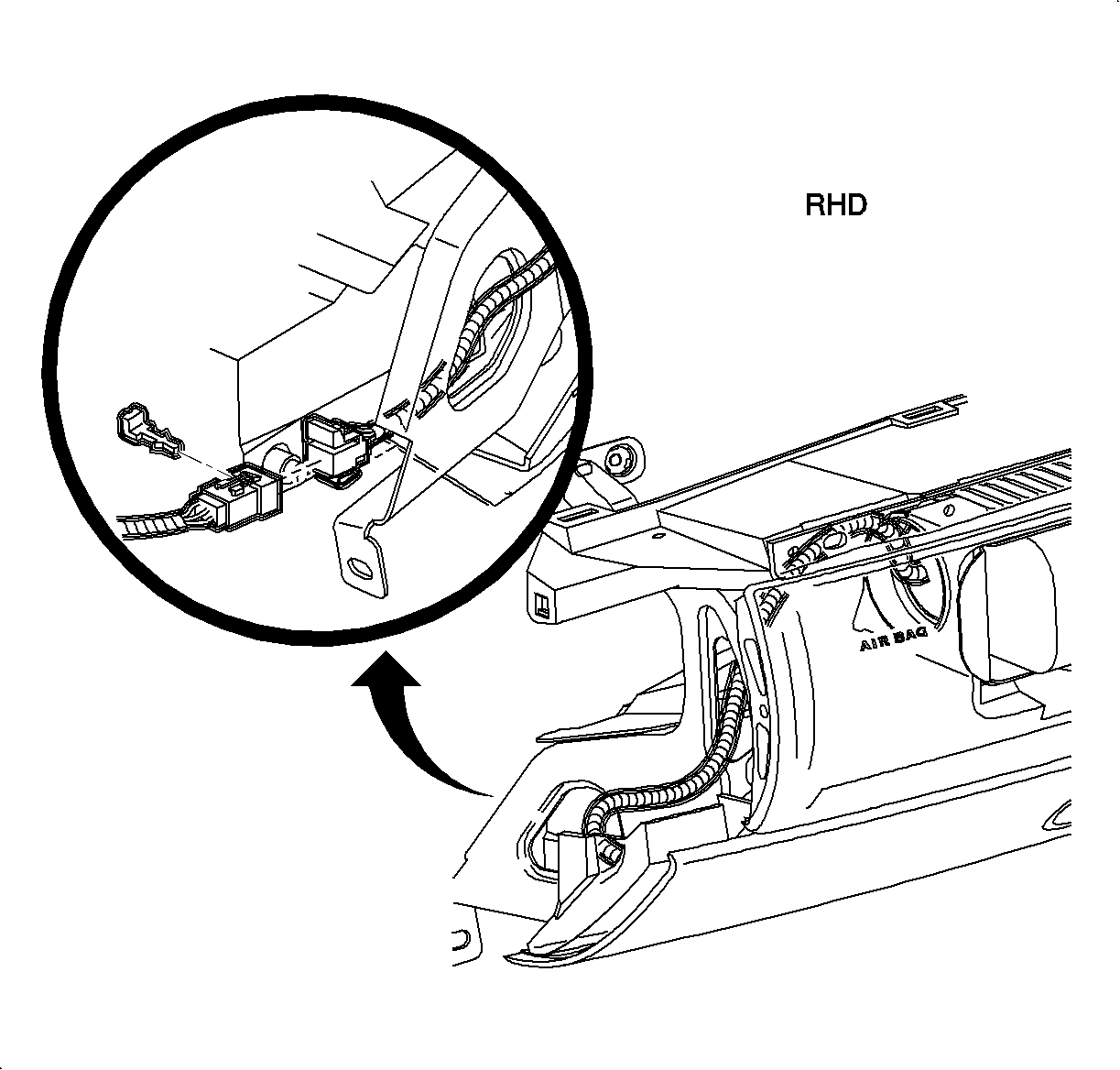
- Remove the passenger
side inflator module:
| 40.1. | Unclip the plastic retainer and lift the inflator module harness out of
the energy absorber. |
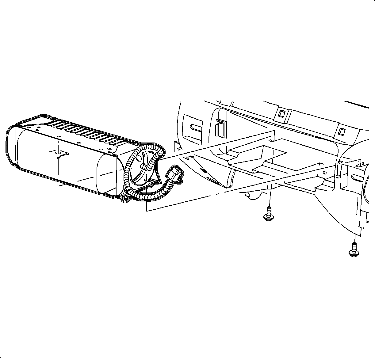
| 40.2. | Remove the screws located underneath the inflator module. |
| 40.3. | Pry the retaining tabs outward that retain the inflator module to the
I/P retainer assembly. |
| 40.4. | Remove the inflator module from the opening. |

- Remove the I/P harness plastic retainer from the H-brace
- Remove the screw and ground wires from the H-brace.
- Remove the radio ground strap from the H-brace.
- Remove the junction block.
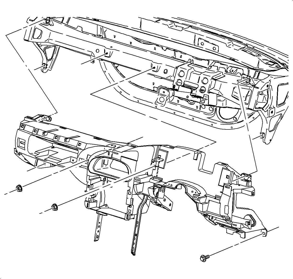
Important: Use the illustration to determine the fastener location and direction of removal.
- Remove the I/P screws and nuts.
Notice: Put I/P retainer assembly on a clean surface so that the assembly surface does
not become damaged.
- Remove the I/P retainer assembly from the vehicle.

- Detach the wiring harness rosebud fastener from the rear of the HVAC module.
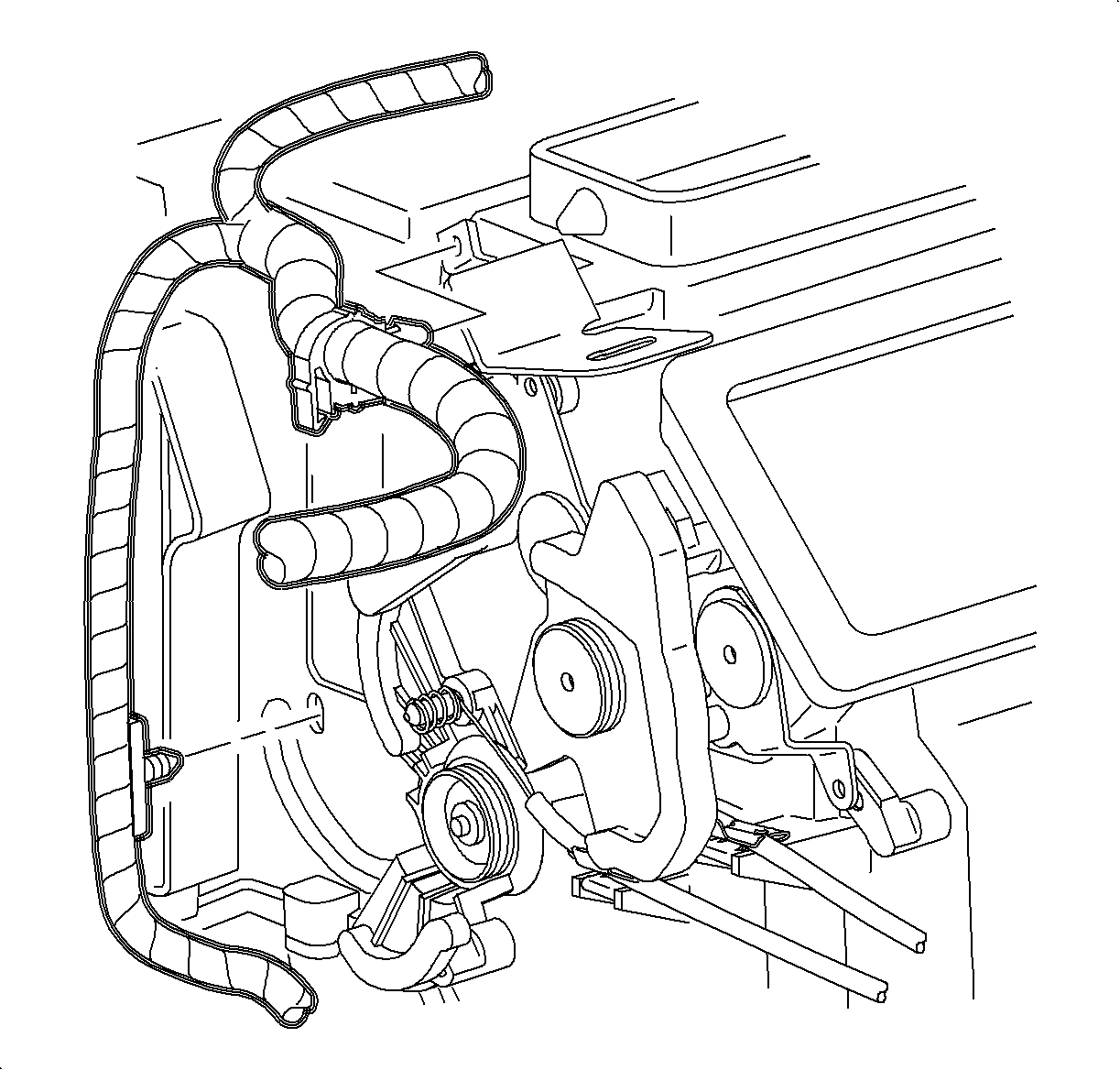
- Remove the wiring harness rosebud fasteners from the side of the HVAC module.
- Remove the wiring harness rosebud fastener from the left module mounting
bracket.
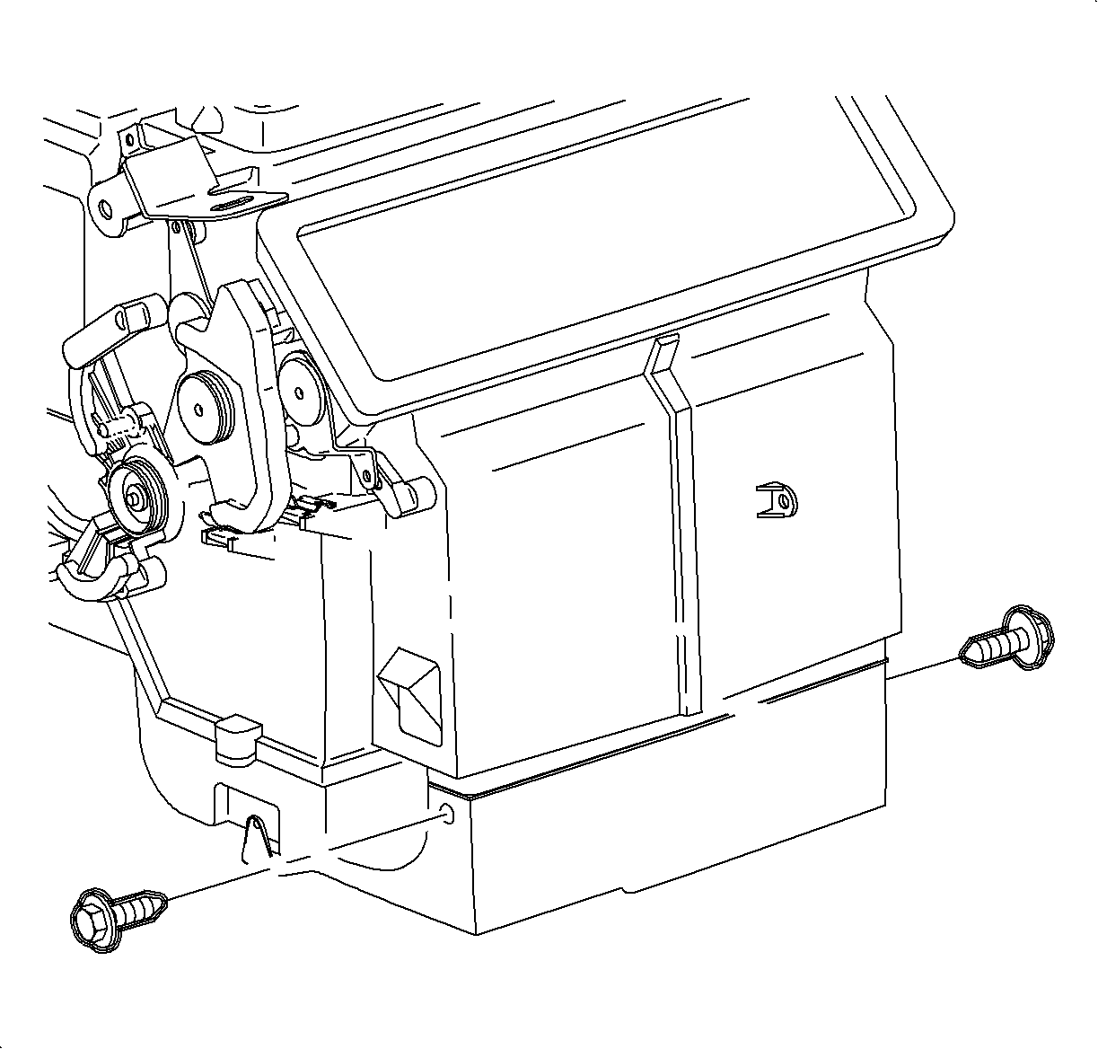
- Remove the lower heater duct screws.
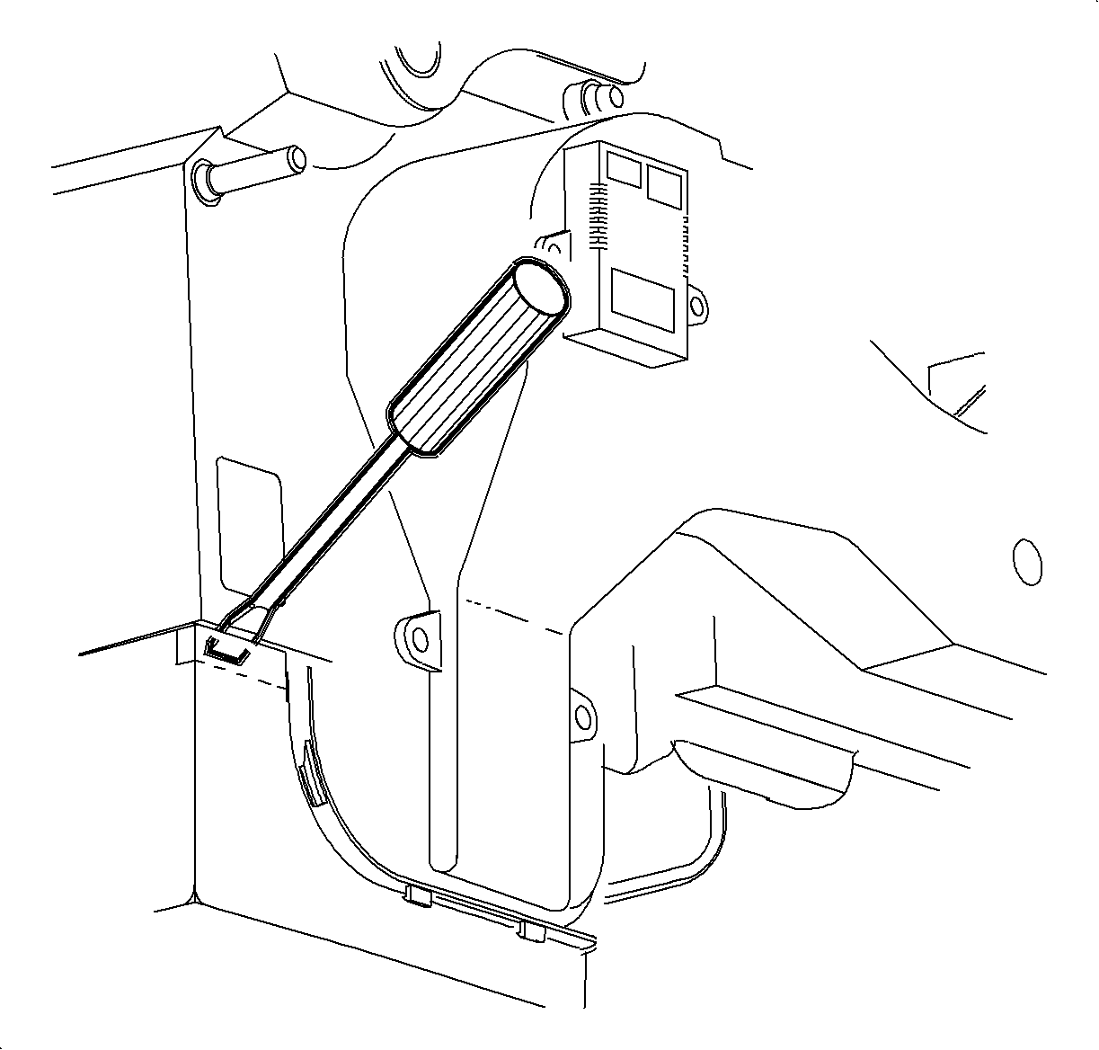
Notice: Be careful not to damage foam seal.
- For Coupes, slide the heater duct downward and then left, into
the passenger side footwell.
- For Sedans/Wagons, use a flat blade screwdriver to bend the right side
heater duct flange outward at the cut lines, then slide the duct left into the passenger
side footwell with the wiring harness.
- Remove the brake transaxle shift interlock cable from the heater duct.
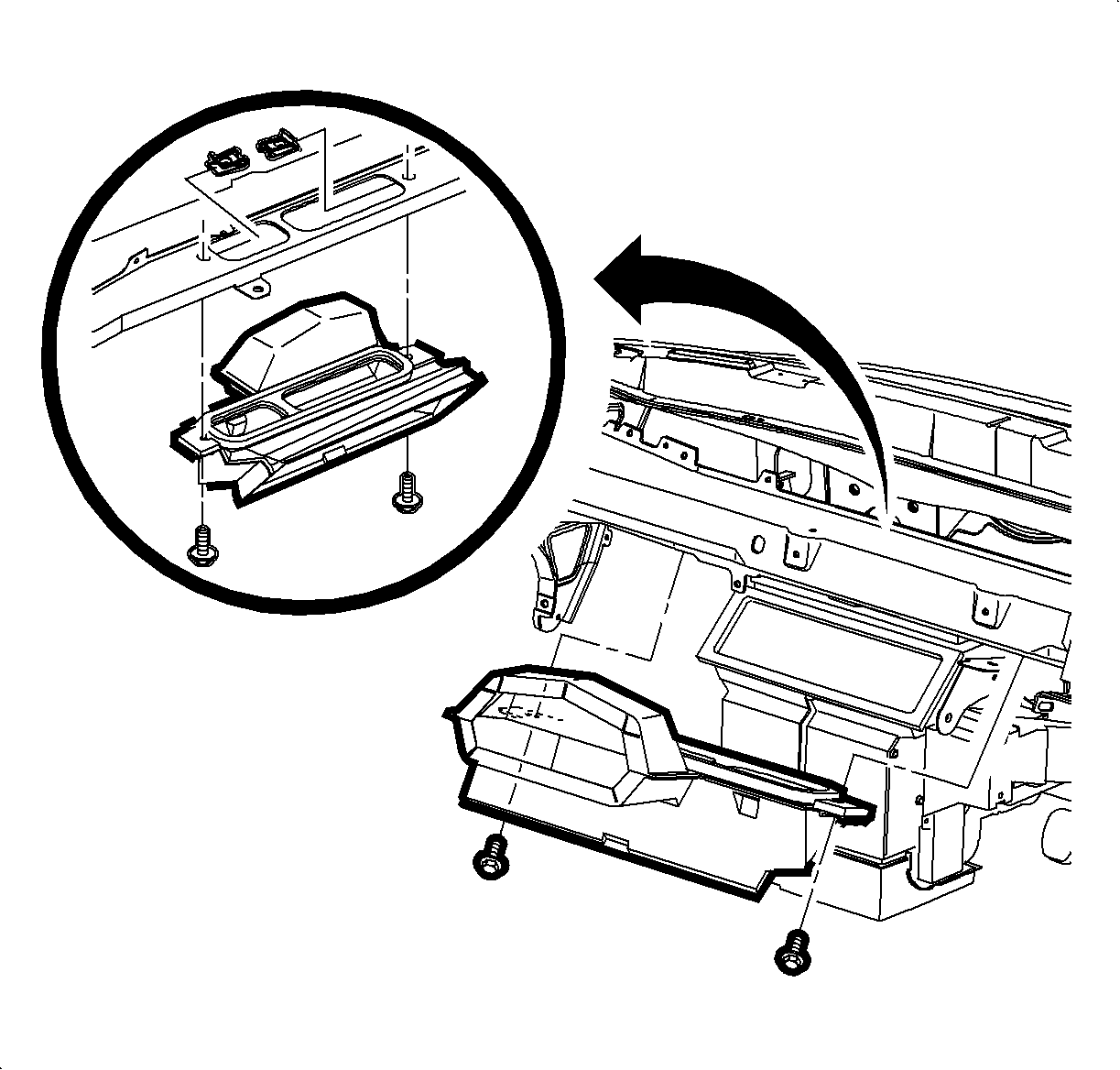
- Remove the screws and the center air outlet duct.
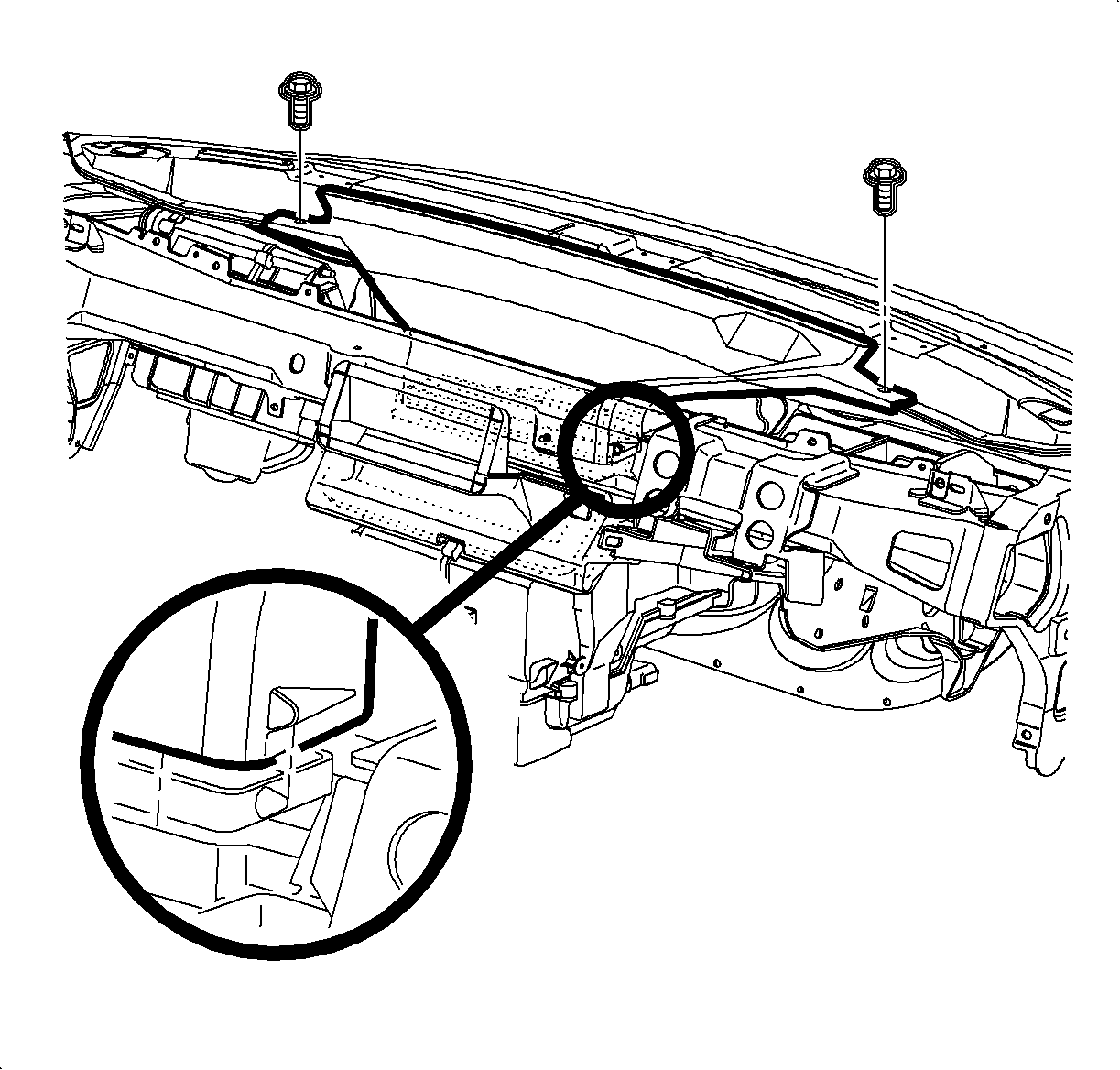
- Remove the screws and unsnap the windshield defroster nozzle from the mode valve
assembly.
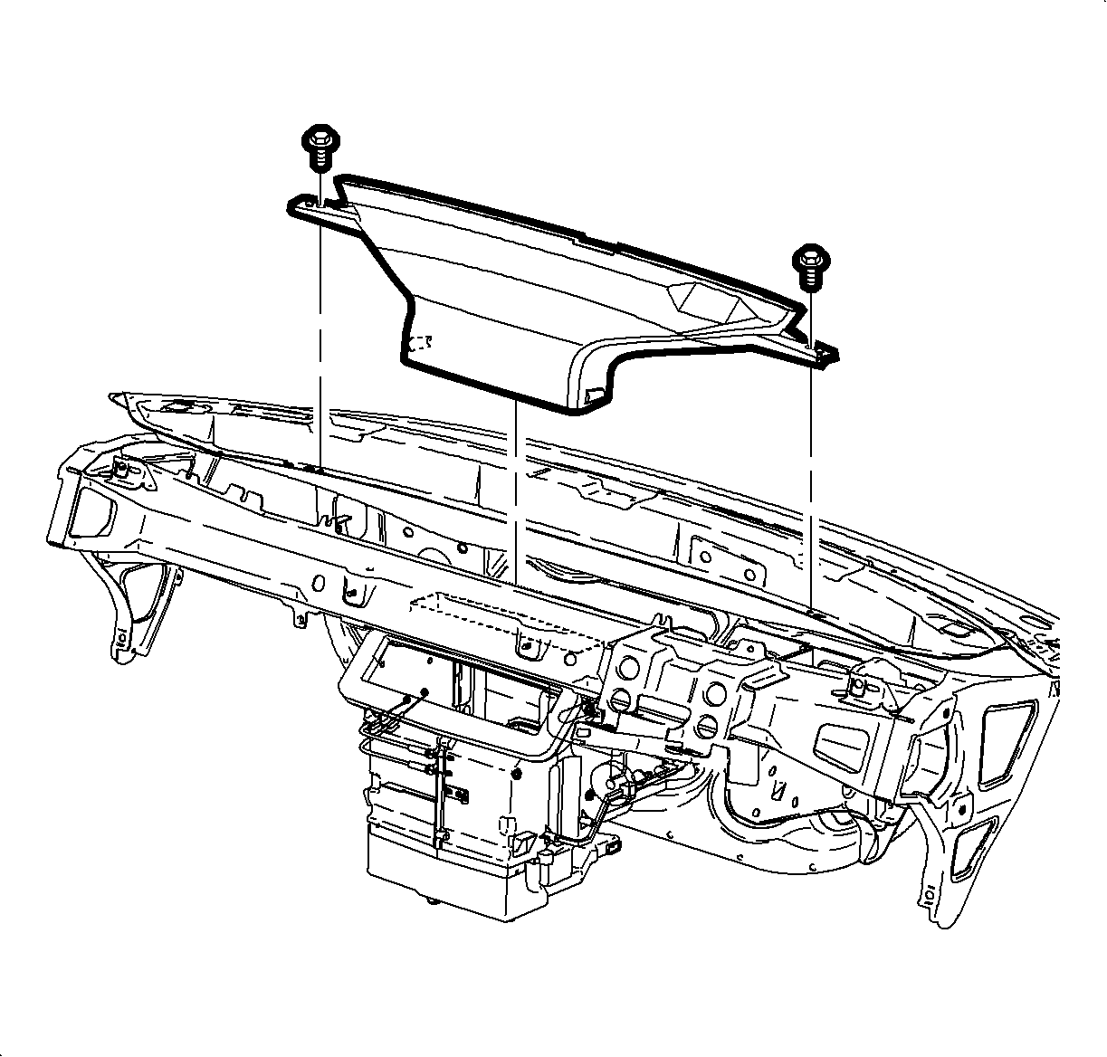
- Remove the defroster nozzle by rotating the front of the nozzle up and away
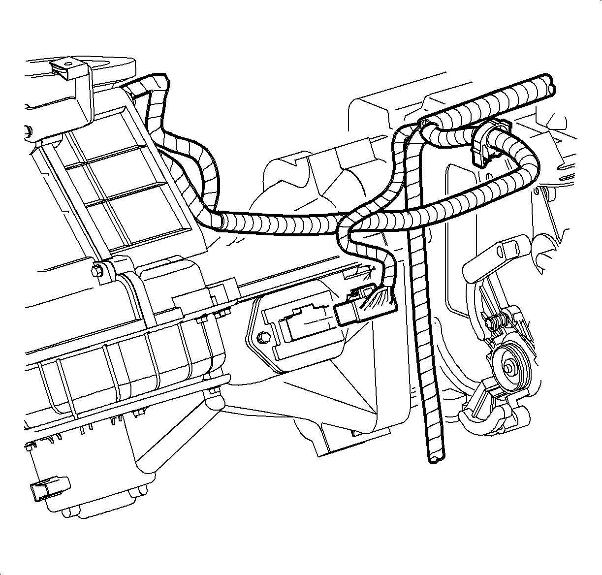
from the windshield.
- Disconnect the blower motor resistor connector.
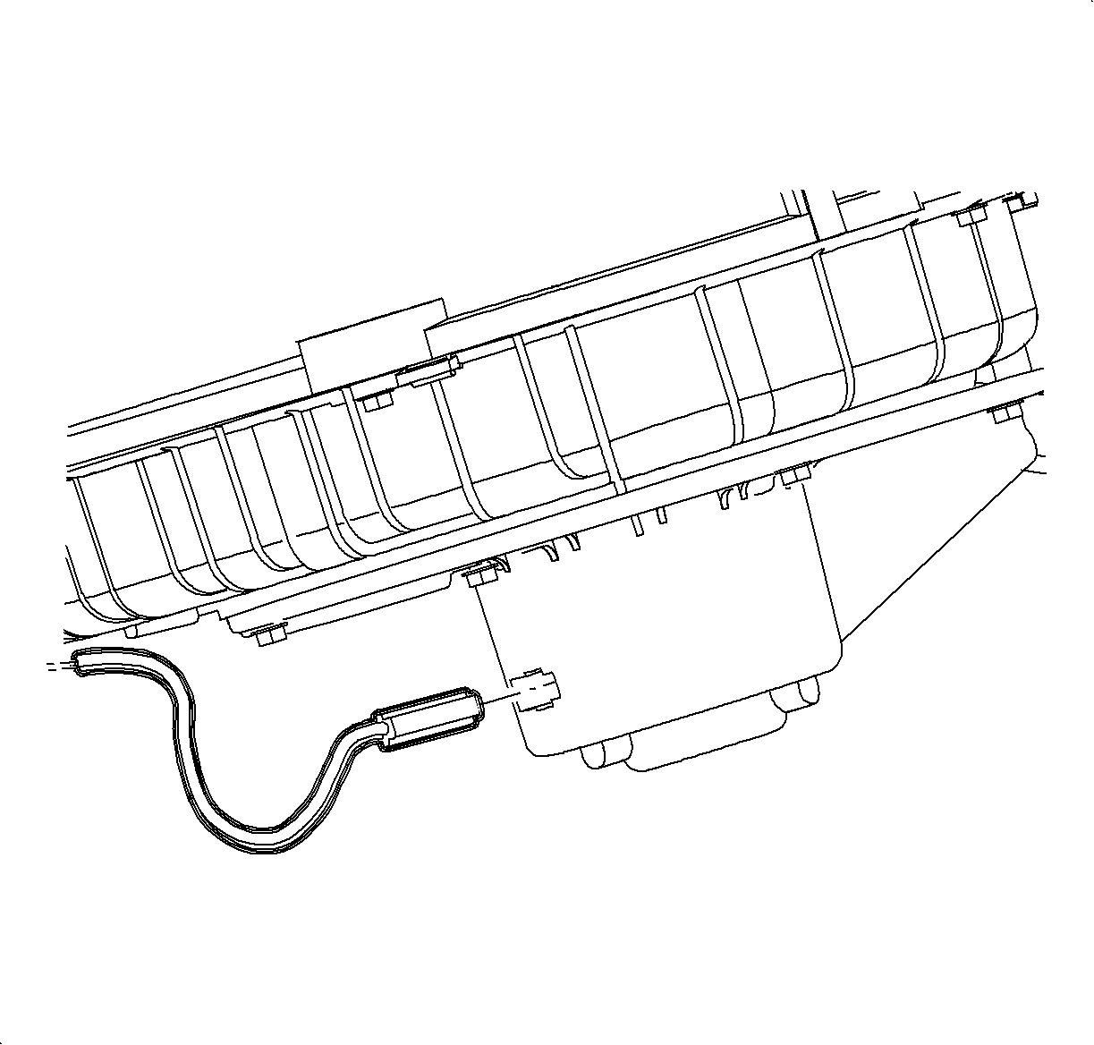
- Disconnect the blower motor electrical connectors.
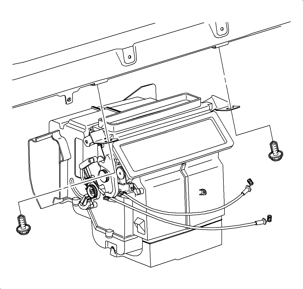
- Remove the HVAC module mounting brackets to the beam bolts.
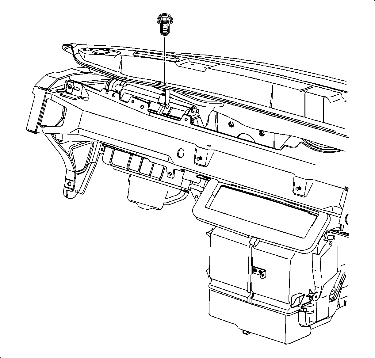
- Remove the blower unit bracket to the cowl screw.
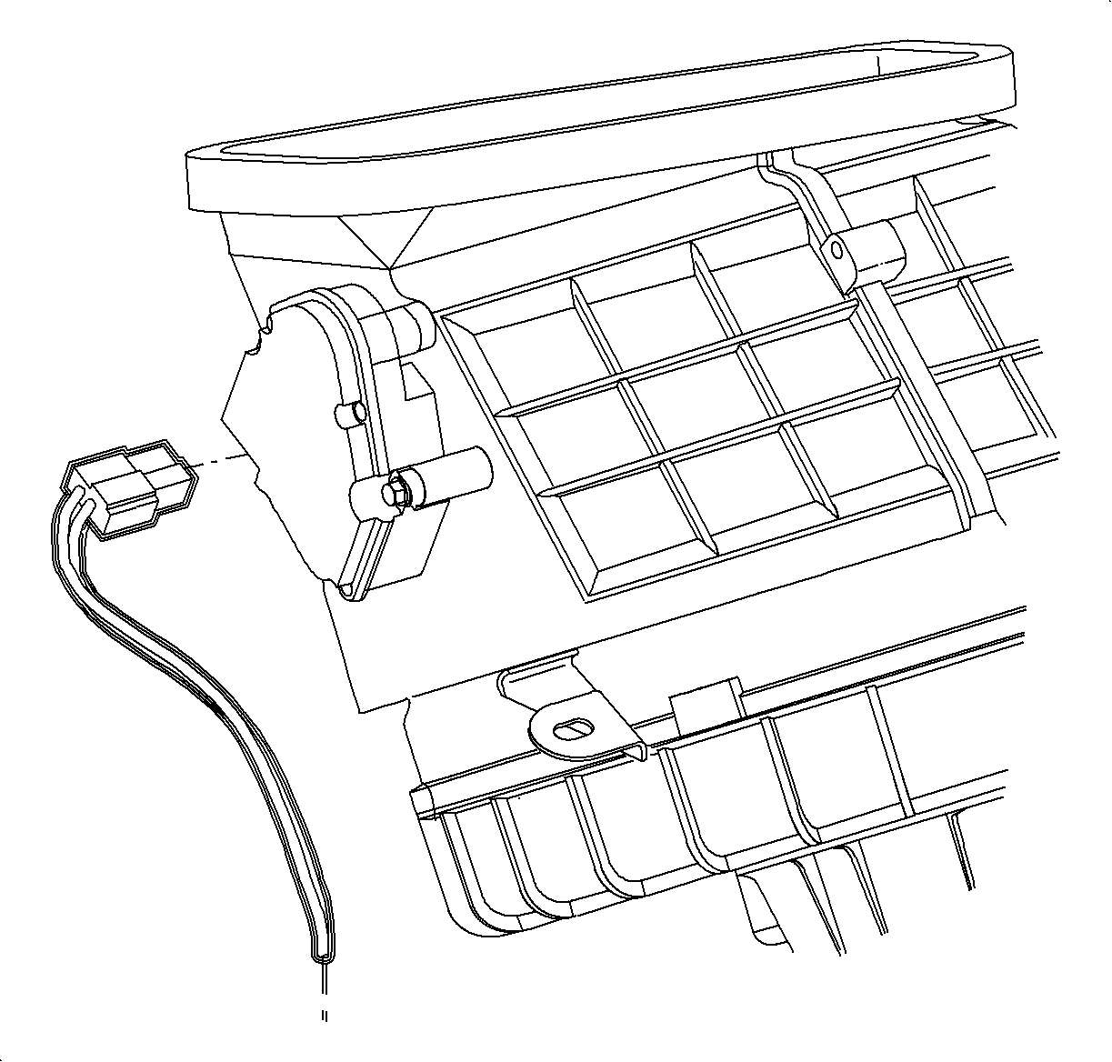
- Disconnect the air valve actuator electrical connector.
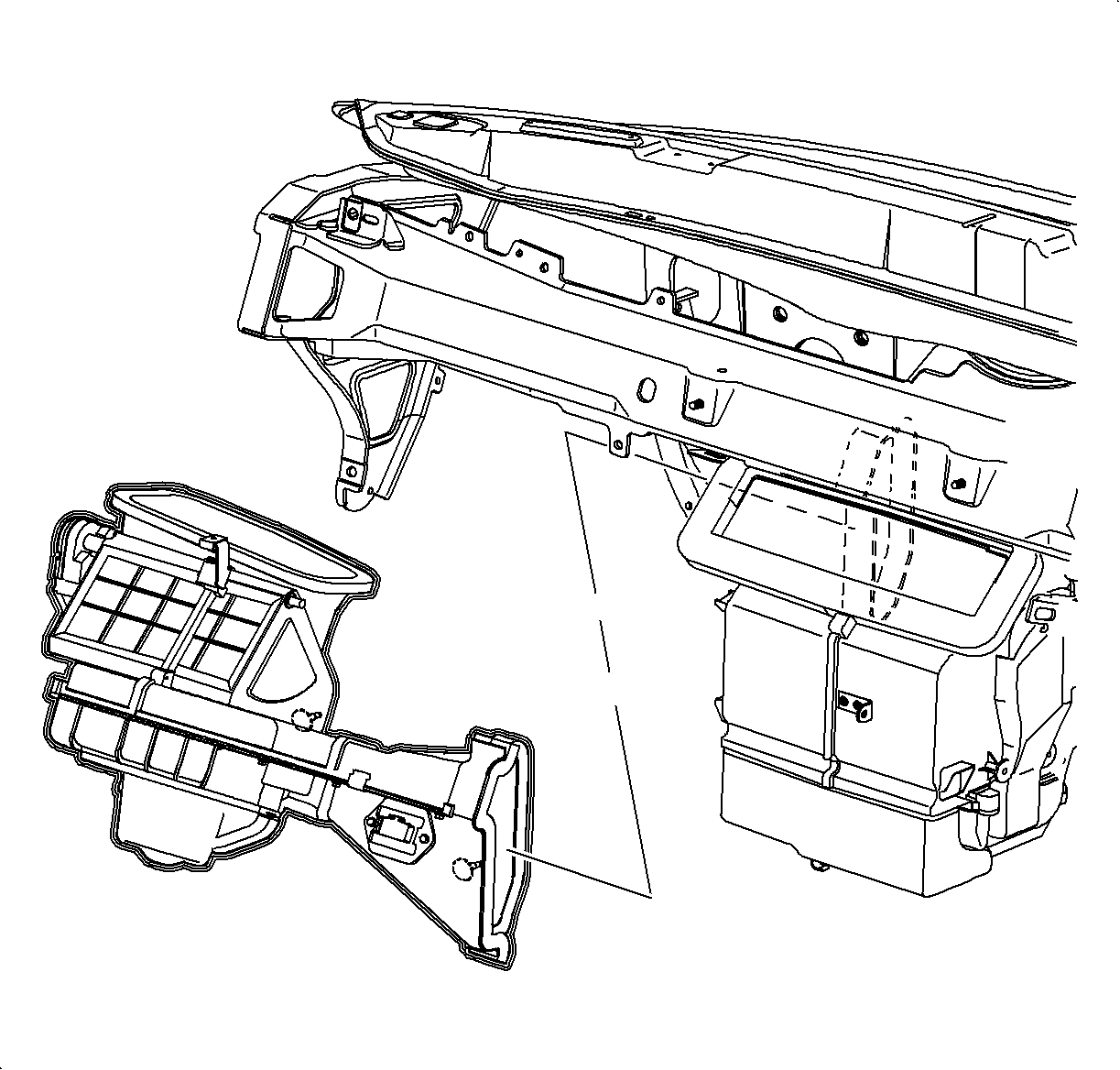
- Remove the blower unit from the vehicle.
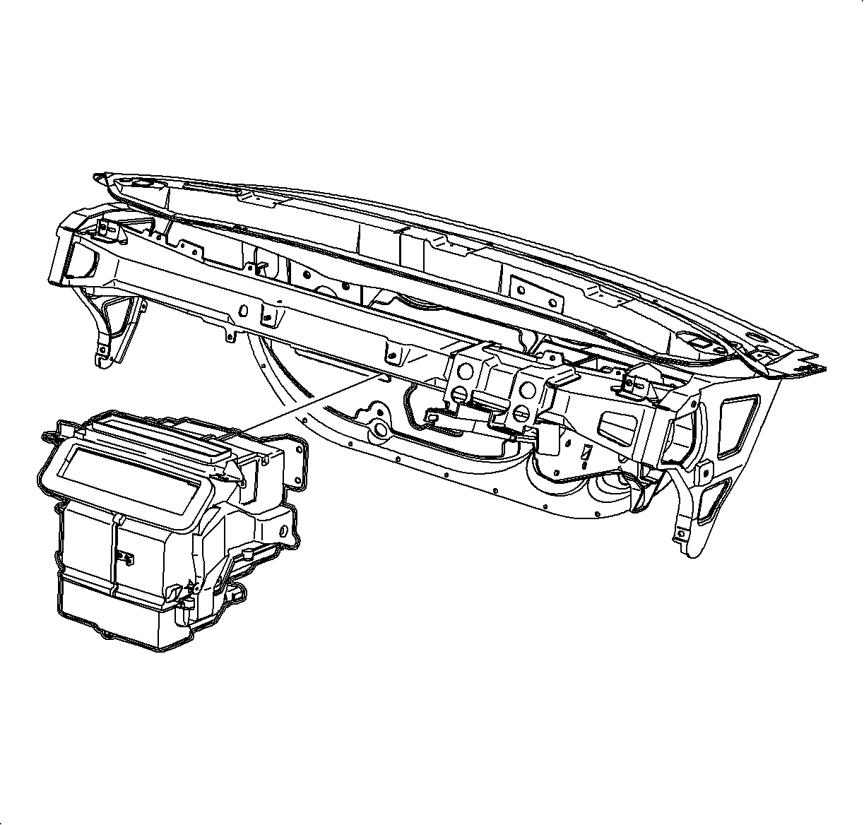
- Remove the HVAC module from the vehicle.
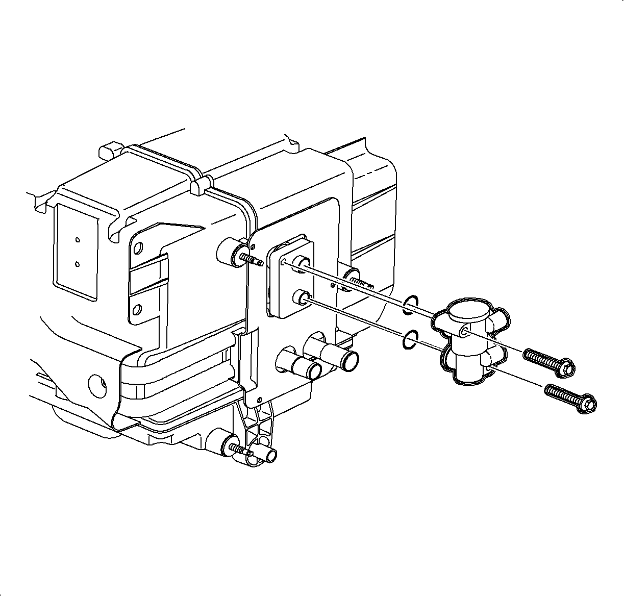
- Remove the thermal
expansion valve from the HVAC module.
- Place the protective cover over the evaporator pipes to prevent contamination
the of A/C system.
Bench Overhaul - HVAC Module (RHD Domestic Only)
Disassembly Procedure
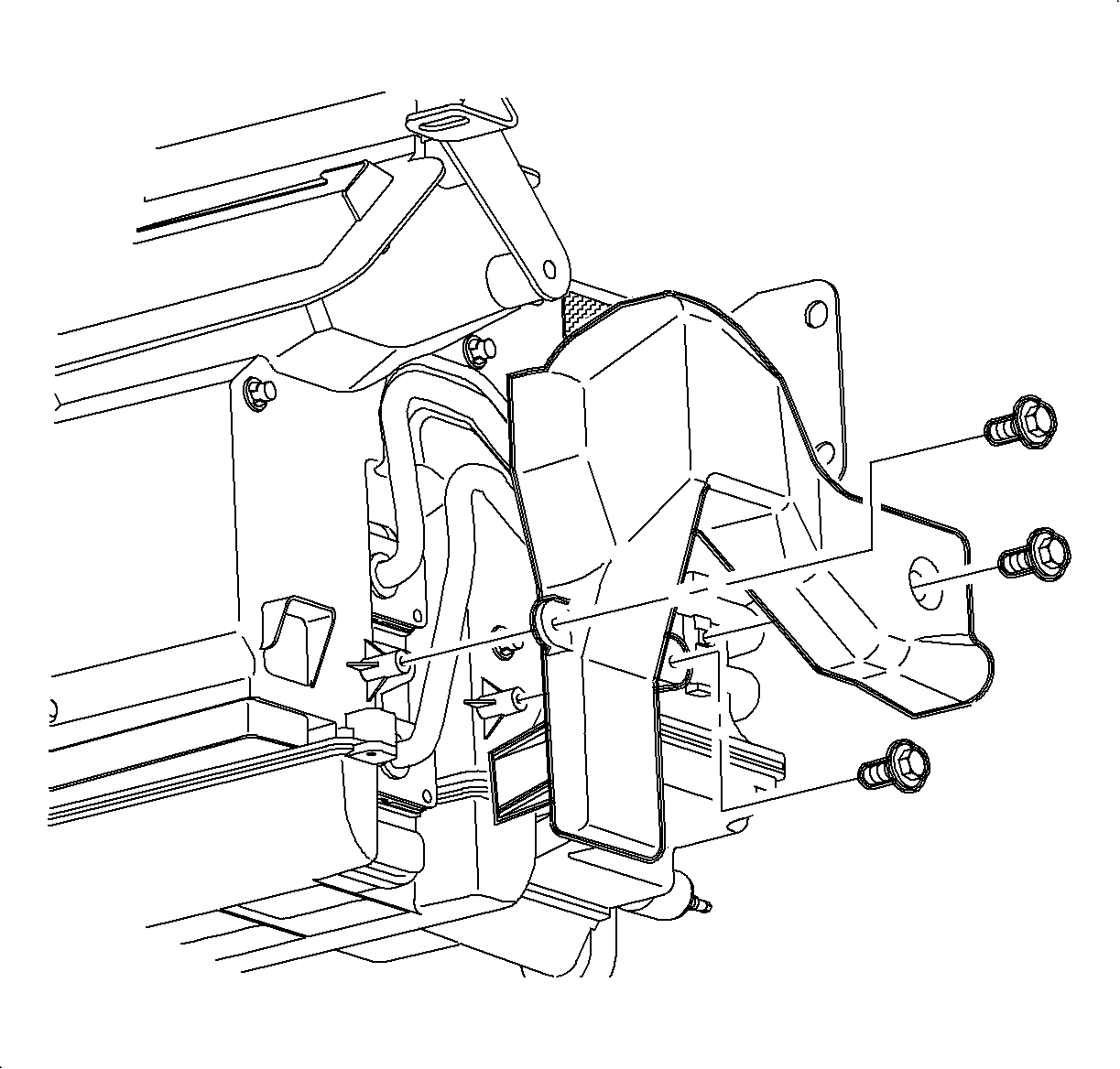
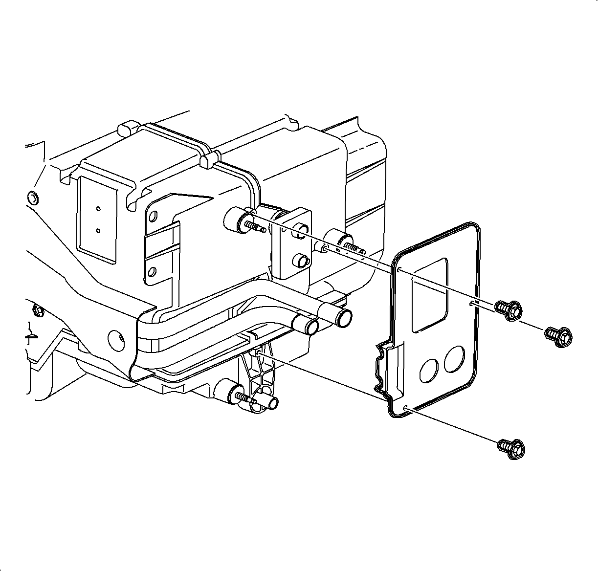
- Remove the pipe cover screws and remove the pipe cover.
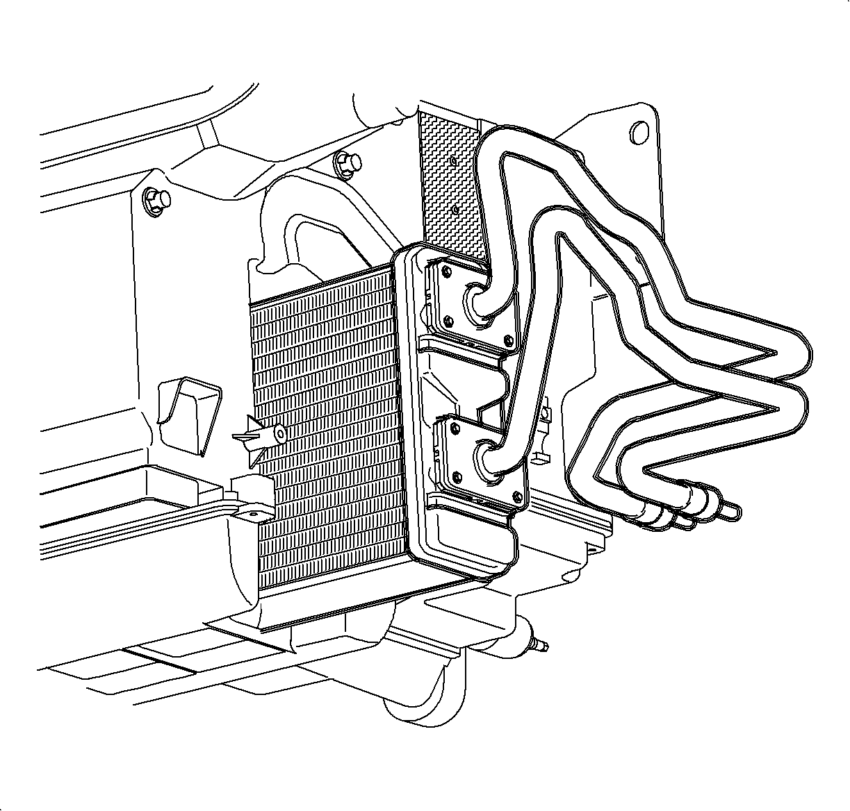
- Remove the pipe support plate screws and remove the support plate.
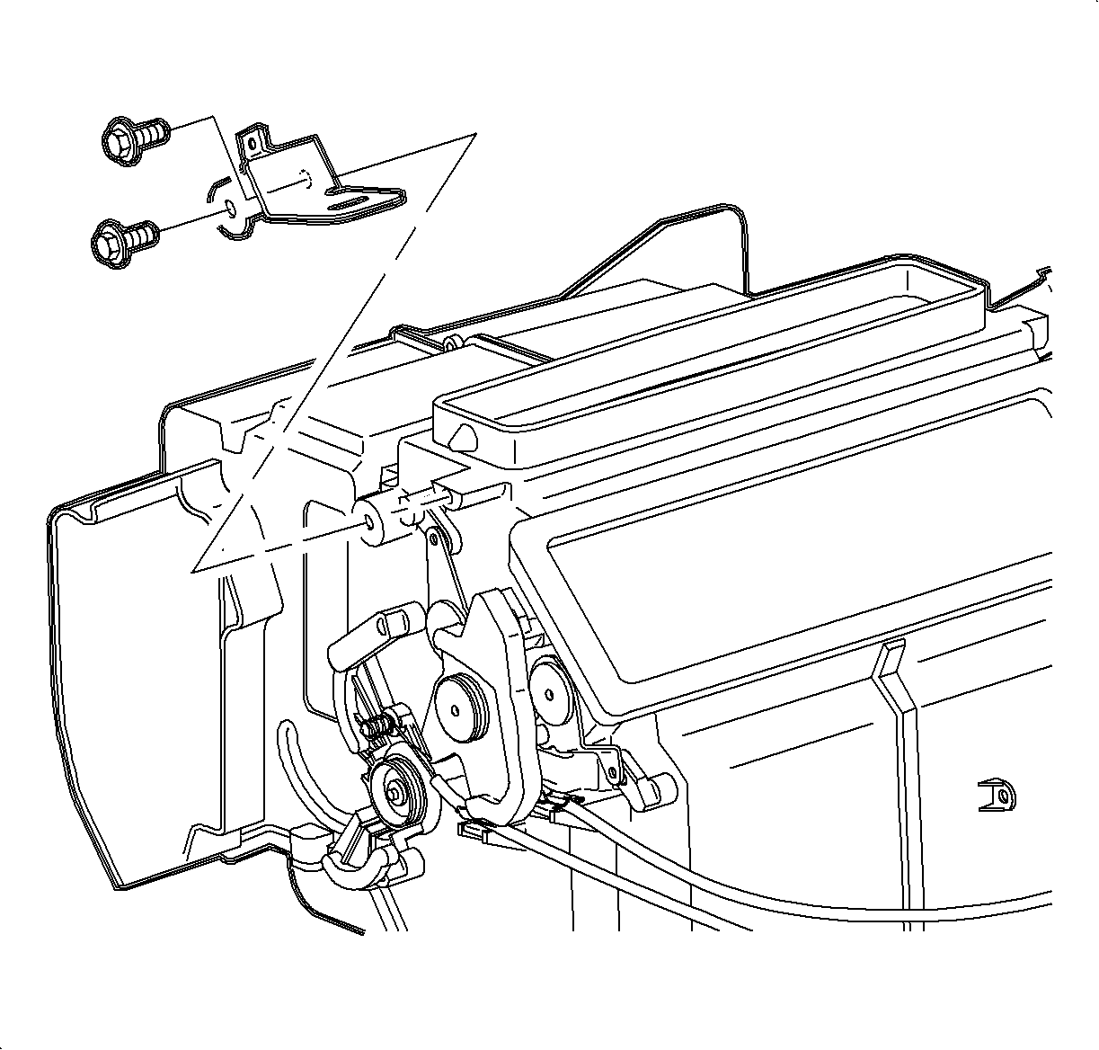
Important: Be careful not to spill any residual coolant from the heater core when removing.
- Remove the heater core assembly from the module case.
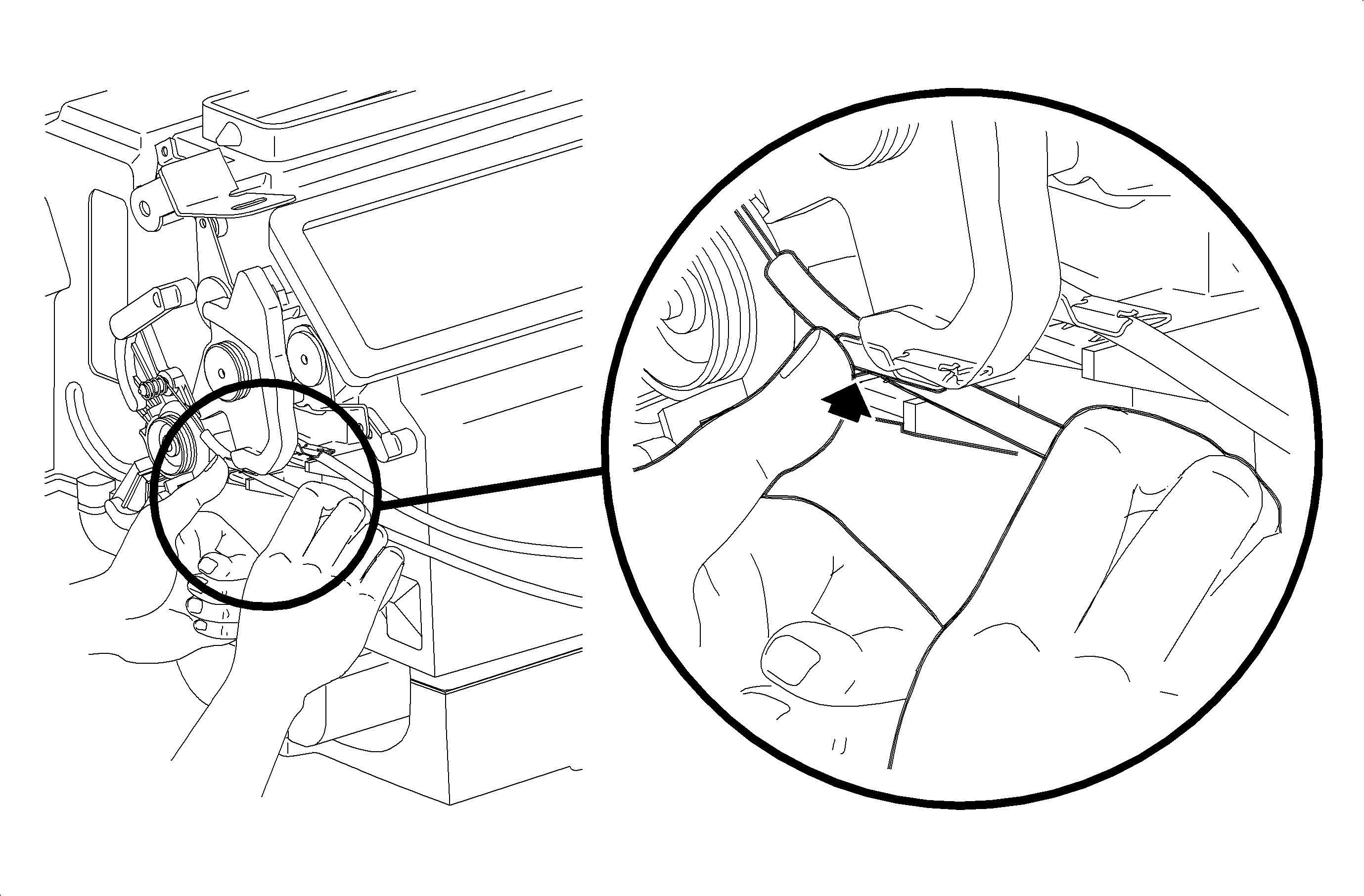
- Remove the left module mounting bracket screws and remove the mounting bracket.
- Release the temperature cable from the retainer clip by pushing upward on the
upper tab of the clip while pulling outward on the cable housing.
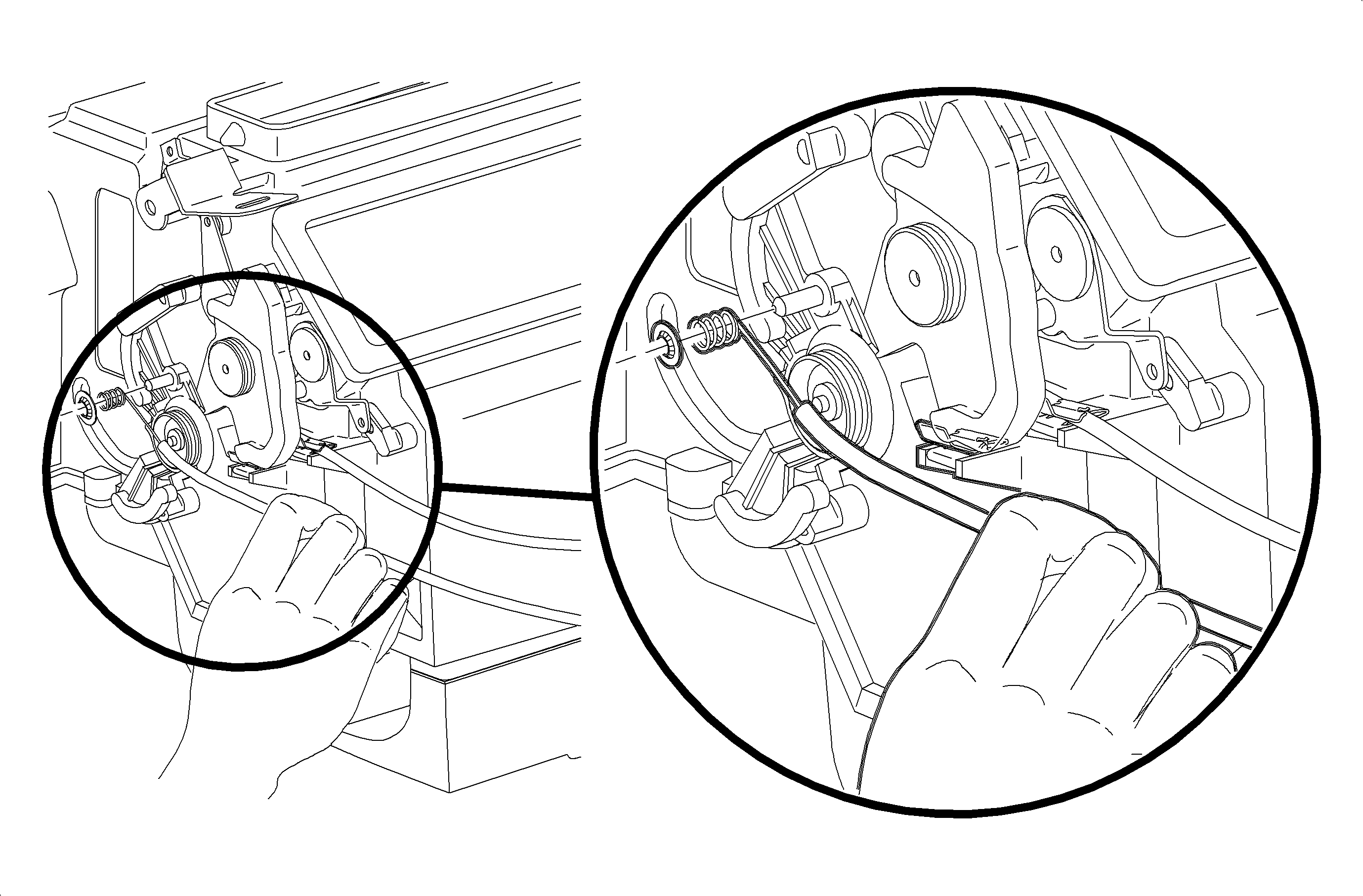
- Remove the temperature cable circular push-on retainer.
- Remove the temperature cable from the temperature cam.
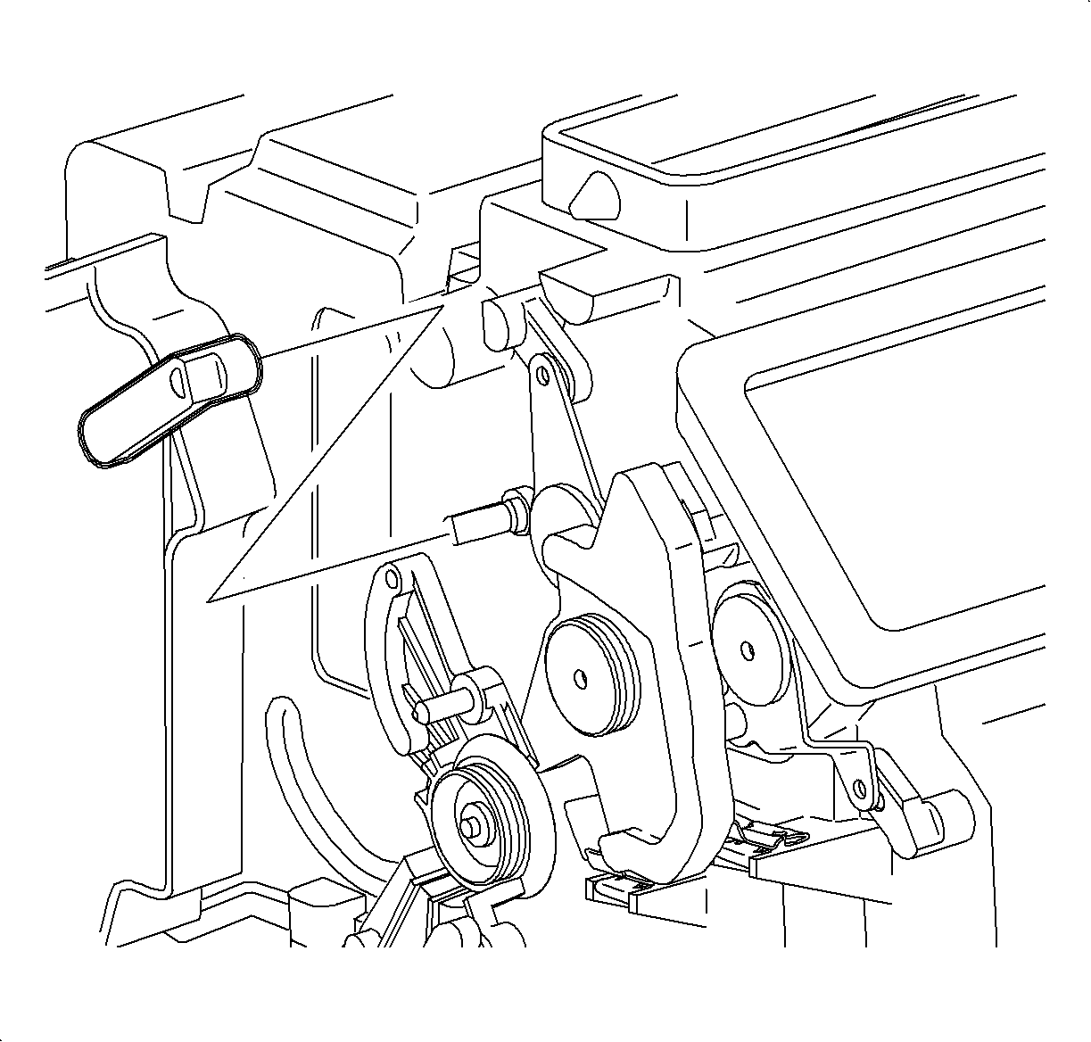
- Use a small flat blade screwdriver to gently pry back the upper mix lever center
tab and pull the upper mix lever off the shaft.
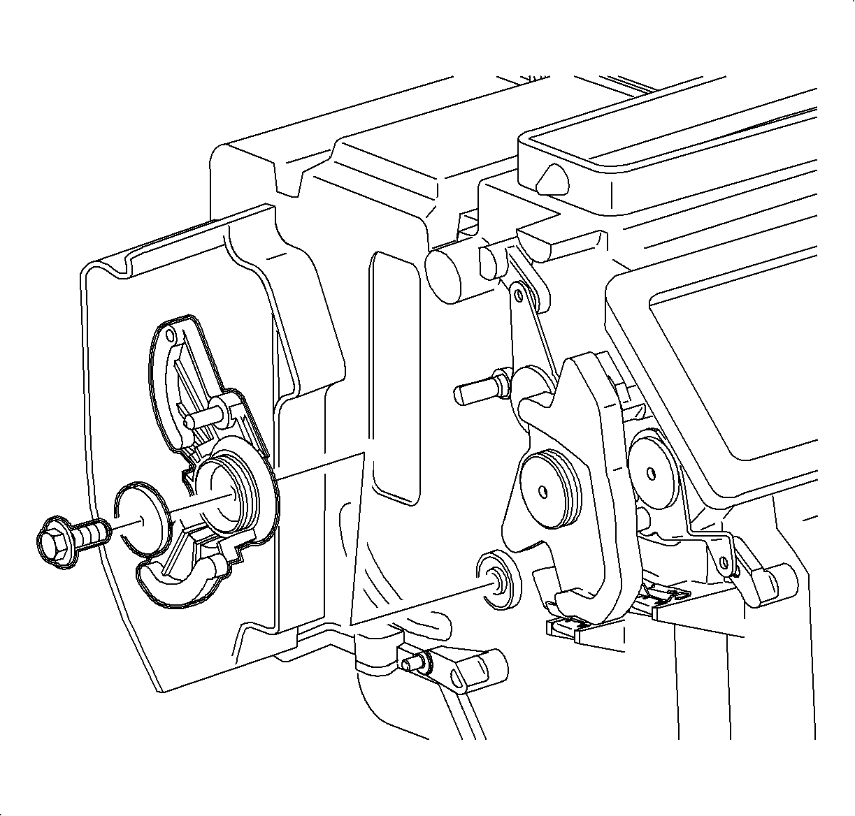
- Remove the temperature cam screw and the washer and remove the cam.
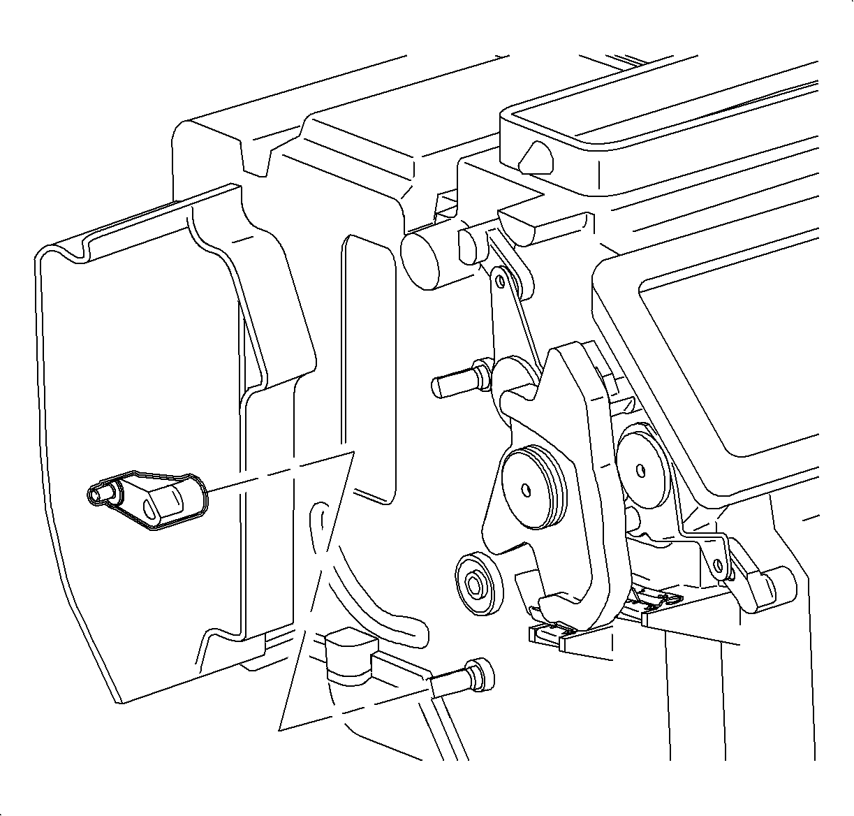
- Use a small flat blade screwdriver to gently pry back the lower mix lever center
tab and pull the lower lever off the shaft.
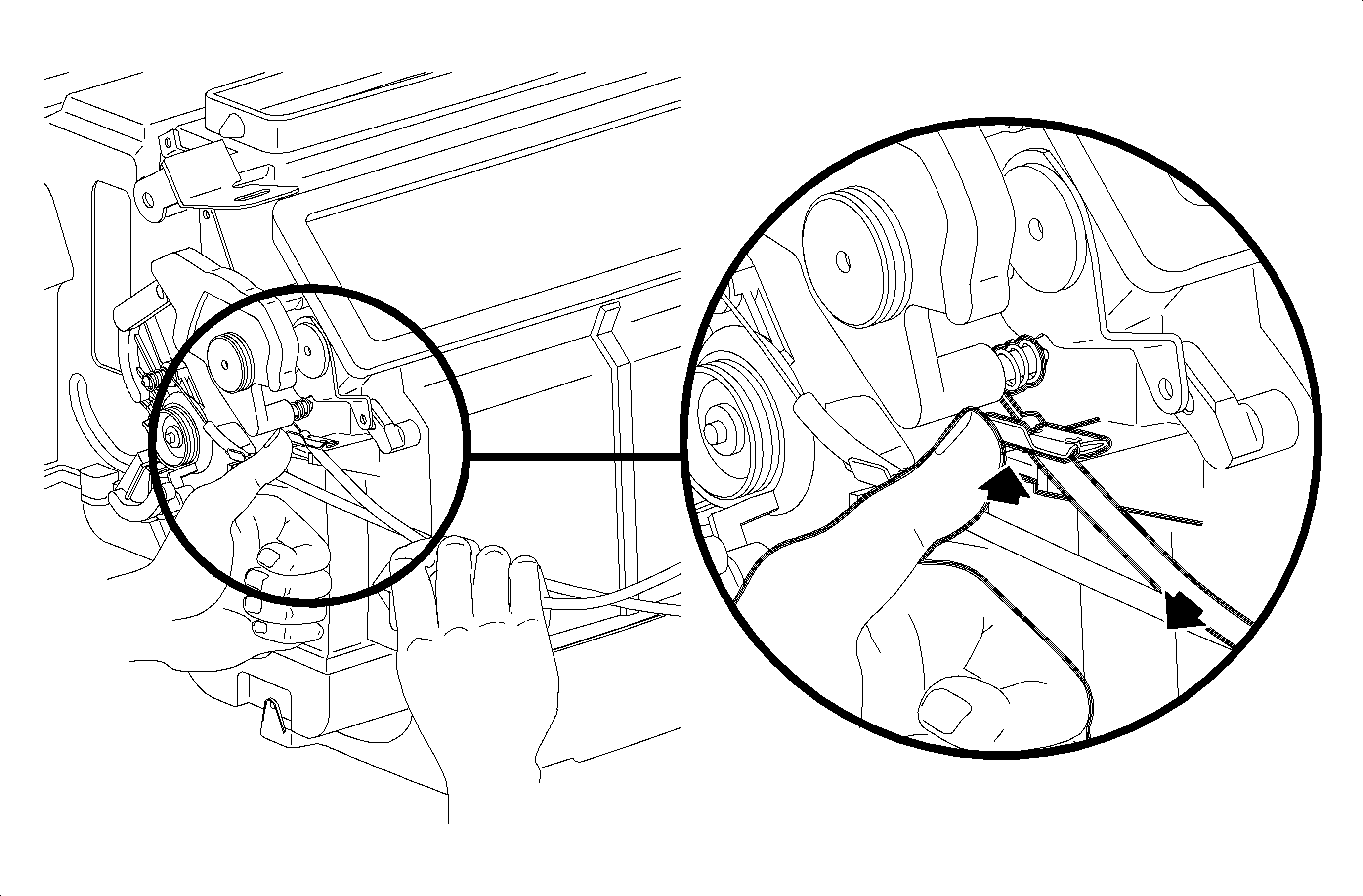
- Remove the mode cable from the retainer clip by pressing upward on the upper
tab while pulling outward on the cable housing.
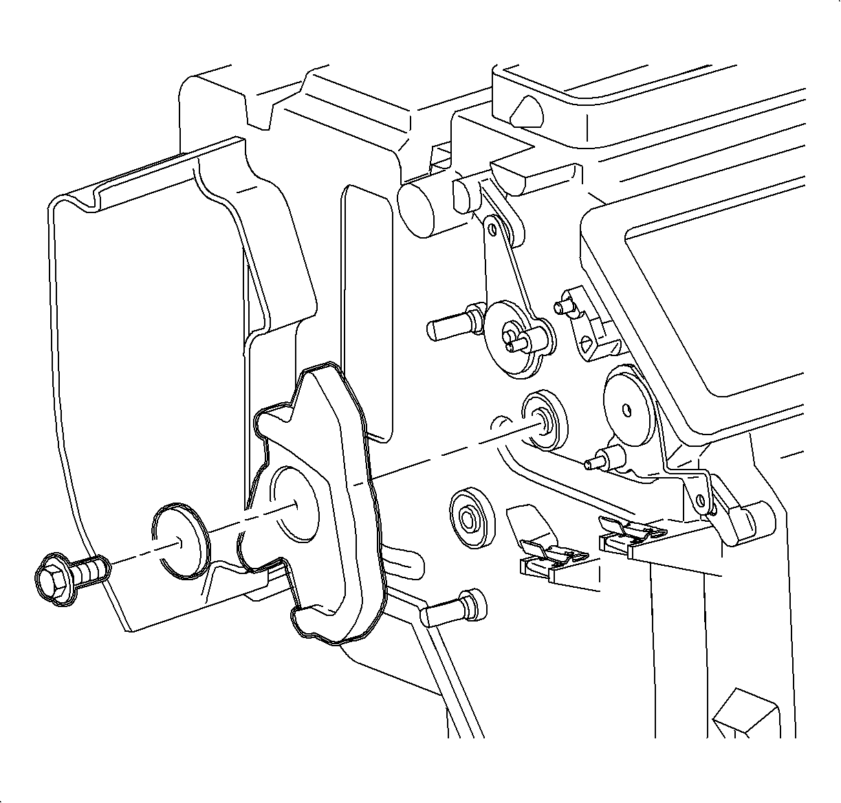
- Remove the mode
cam screw and the washer and pull the cam outward to disengage the mode cable eyelet.
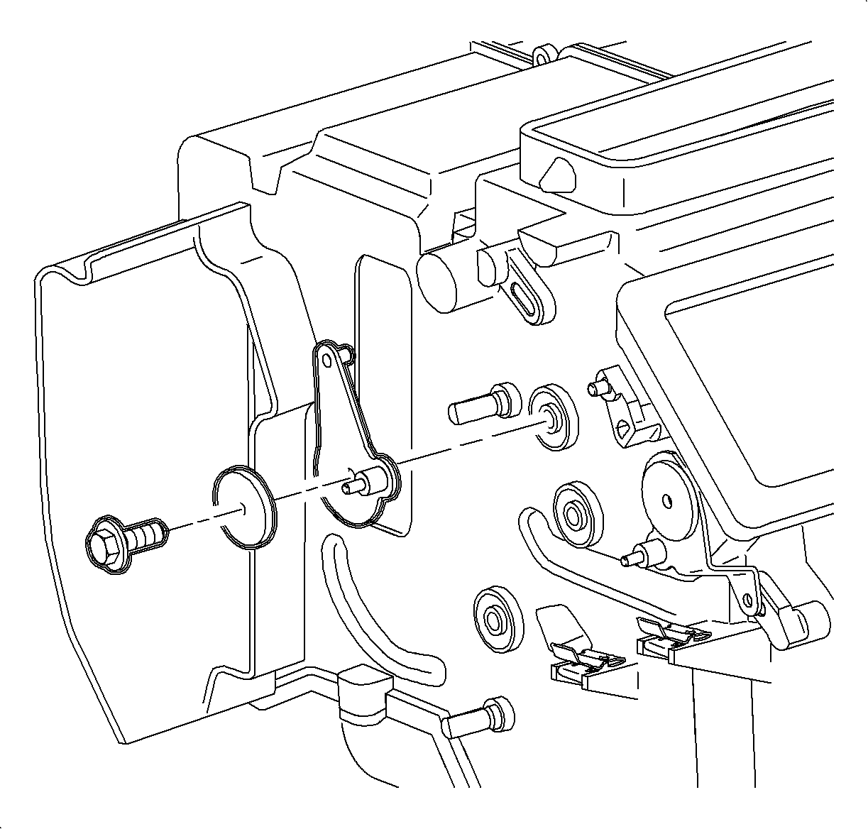
- Remove the defroster door sub-lever screw and washer and remove the lever.
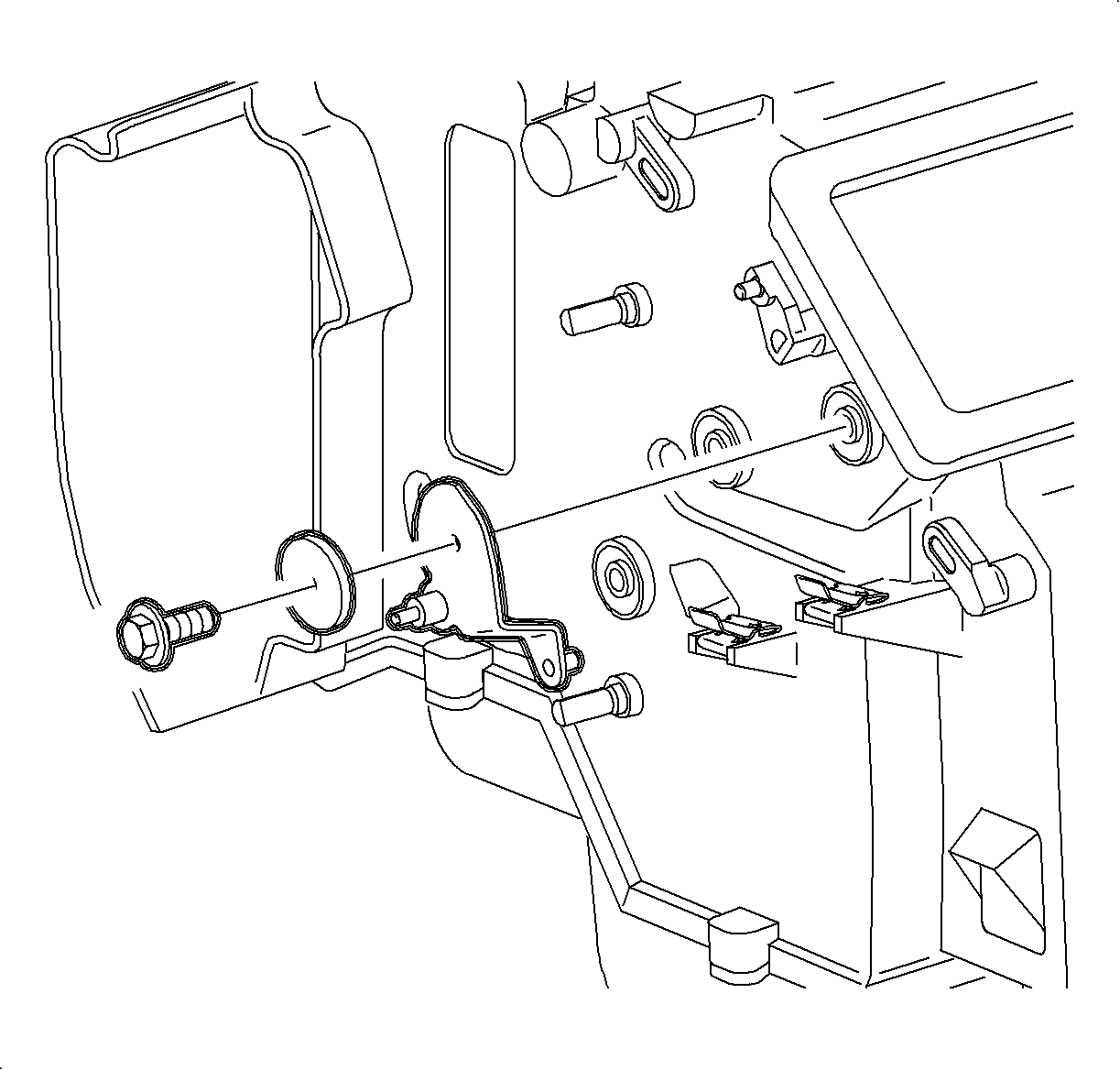
- Remove the heater door sub-lever screw and washer and remove the lever.
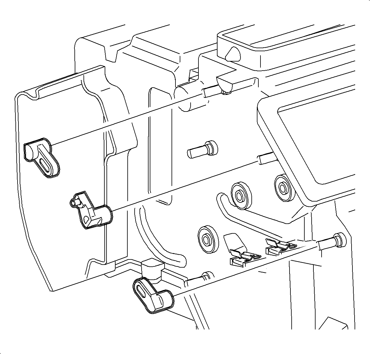
- Using a small flat blade screwdriver, gently pry back
the center tabs and pull the defroster lever, the vent lever, and the heater lever
off of the shafts.
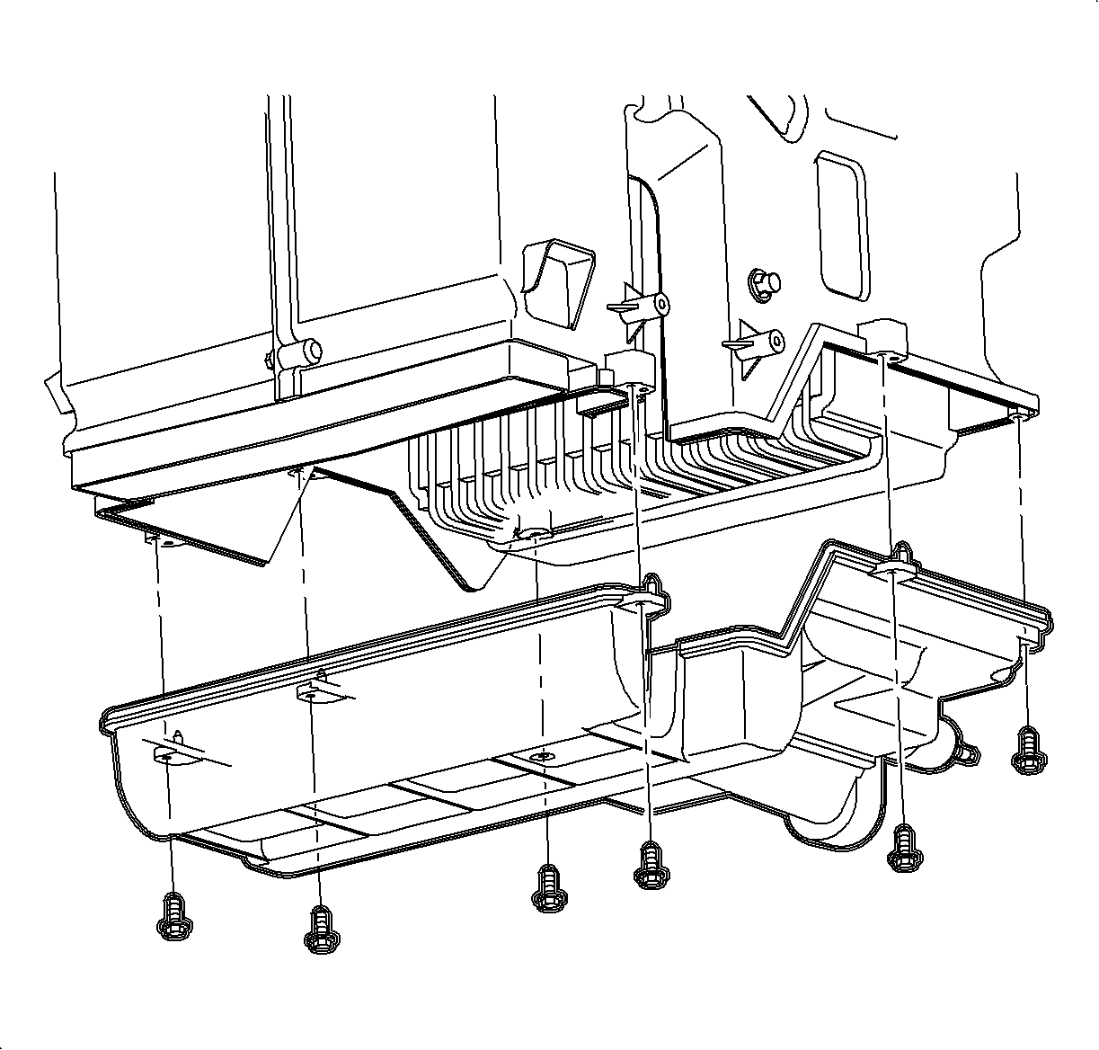
- Remove the lower case screws and remove the lower case.
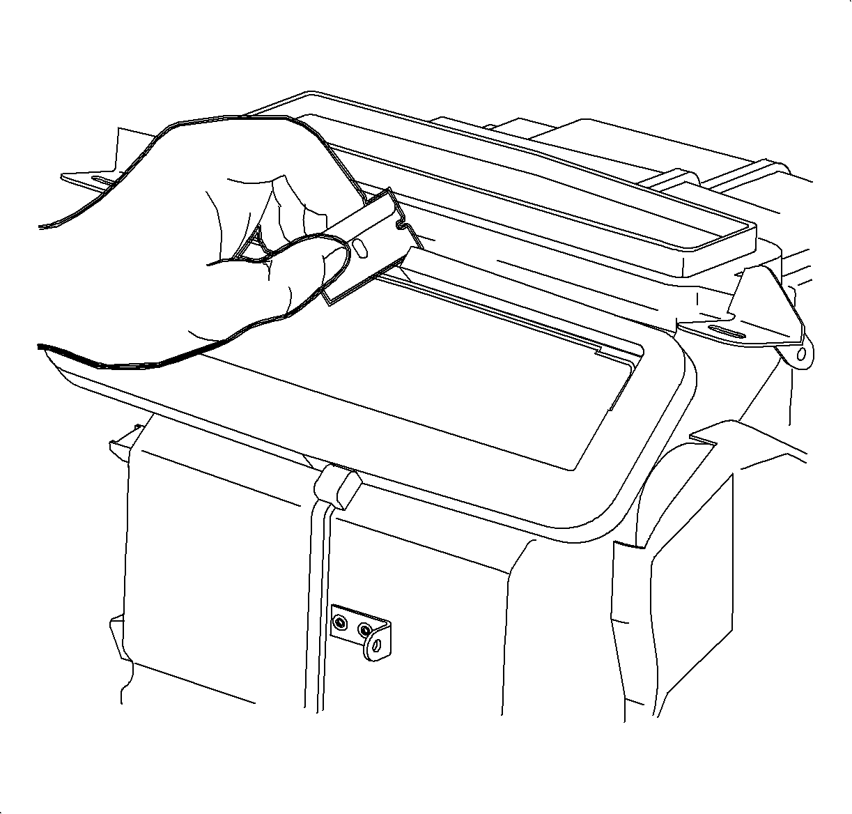
- Use a razor blade to carefully cut the defroster and vent foam seals at the
centerline.
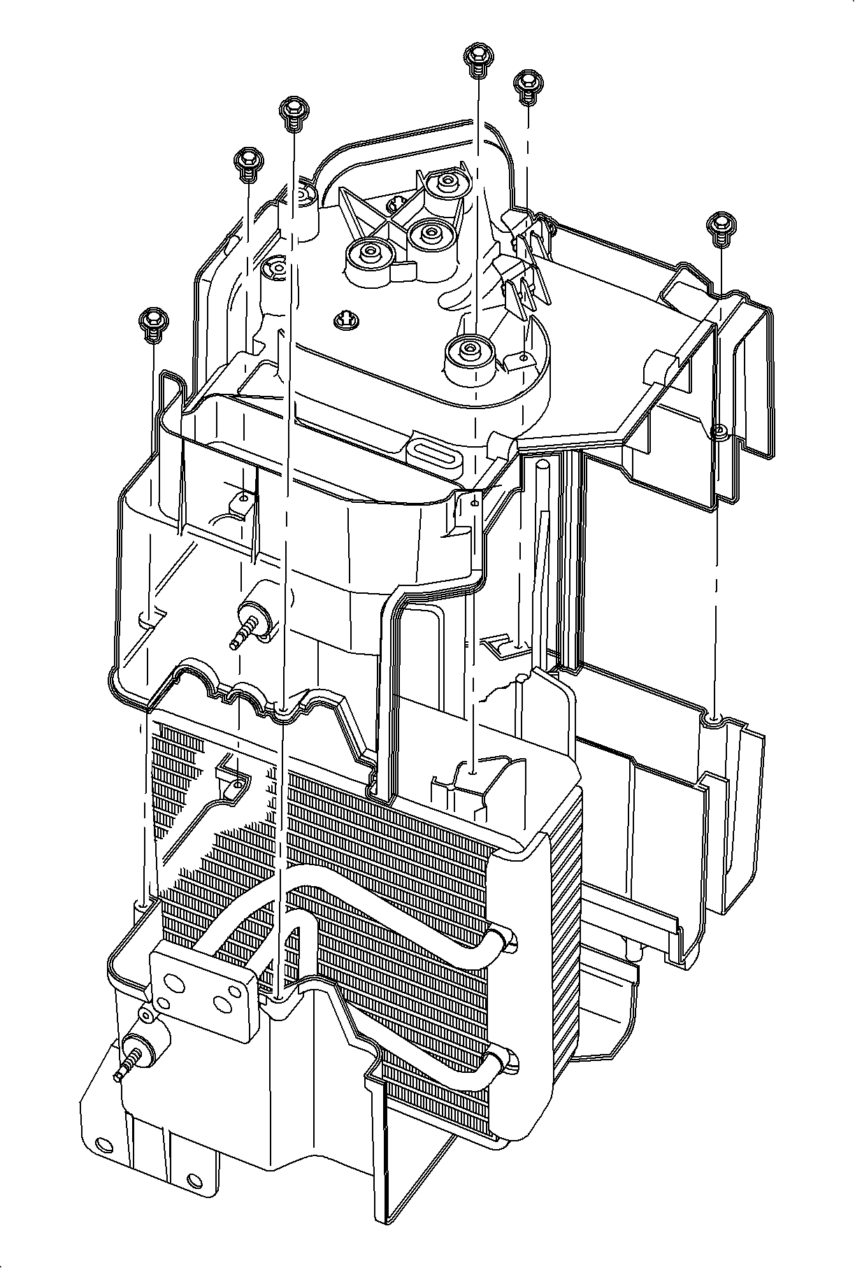
Important: One screw is located in deep cavity to the right of the mix cam.
- Remove the case screws and lift straight up to separate the 2 halves of the
case.
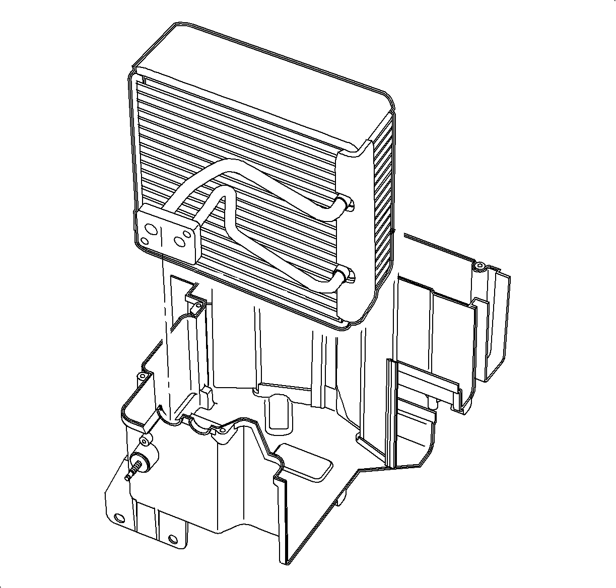
- Remove the evaporator core.
Installation Procedure
Important: When installing a new evaporator core, 67 ml (2.25 oz) of PAG
oil must be added to the core. Replace the evaporator pipe cover before installing
the core.

- Install the evaporator core into the right side of the HVAC module case.
Important: The left case half cross support must interlock with the right case half cross
support.

Important: When properly seated, the module case tongue and groove seal will fit together
snugly.
- Install the left half of the HVAC module case over the core and align the door
shafts with the openings. Press the halves together until seated.
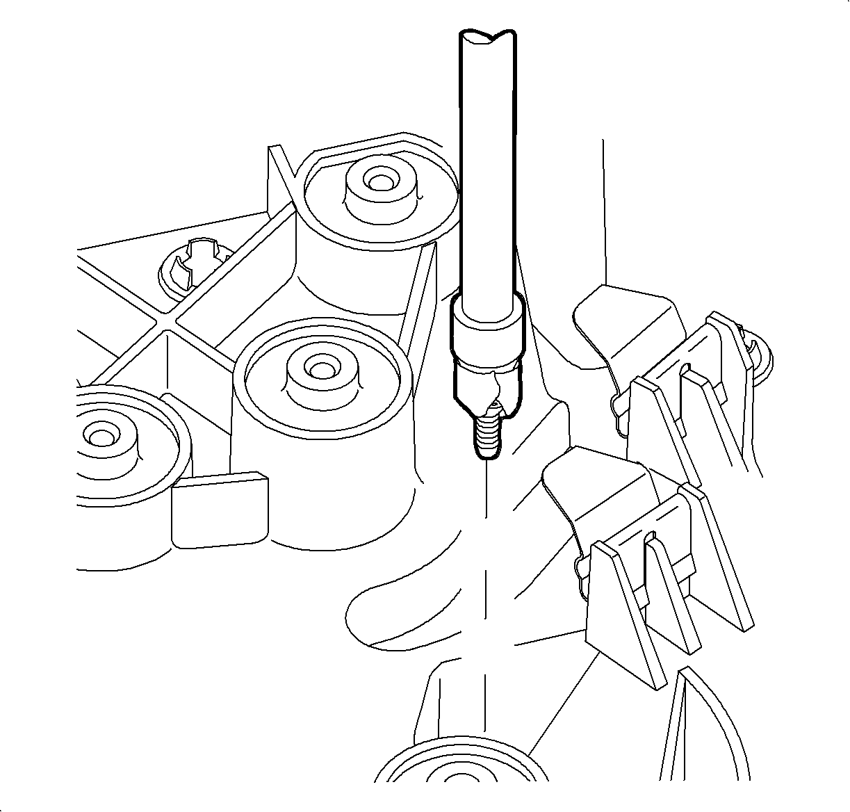
- Install the case screws. When installing the center screw, use a piece of tape
to hold the screw to the socket until the threads are started.

Important: When properly seated, the module case tongue and groove seal will fit together
snugly.
- Install the lower case.
- Install the lower case screws.

- Install the heater core assembly. Press the core into the HVAC module case until
the pipes contact the pipe cover attachment boss.

- Install the heater core pipe cover and screws.

Important: All plastic cam levers have molded in part names and numbers. Refer to the cam
illustration chart for part location information. All levers must be installed with
the retention tang outward. Applying pressure to the opposite end of the door shaft
may aid in seating the tang into the shaft notch.
- Install the defroster lever labeled DEF onto the defroster door shaft until
the tang seats into the shaft notch.
- Install the vent lever labeled VENT 1301 onto the vent door shaft
until the tang seats into the shaft notch.
- Install the heater lever labeled VENT 1401 onto the heater door
shaft until the tang seats into the shaft notch.

- Position the metal heater sub-lever on the module boss with the pin set into
the heater door lever.
- Install the heater sub-lever washer and screw.
- Rotate the heater sub-lever to verify the smooth operation of the levers
and heater door.

- Position the metal defroster sub-lever on the module boss with the pins set
into the defroster door lever.
- Install the defroster sub-lever washer and screw.
- Rotate the defroster sub-lever to verify the smooth operation of the lever
and defroster door.

- Install the mode
cam on the center boss. Align the defroster sub-lever, the vent lever, and the heater
sub-lever so that each pin is the proper mode cam track.
- Install the mode cam washer and screw.
- Rotate the mode cam to verify the smooth operation of all the doors, levers,
and sub-levers.
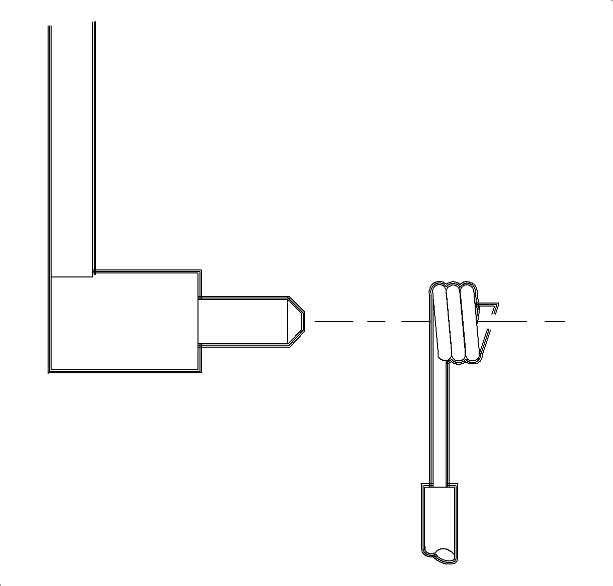
Important: Install the mode cable with the wire eyelet wrap as shown.
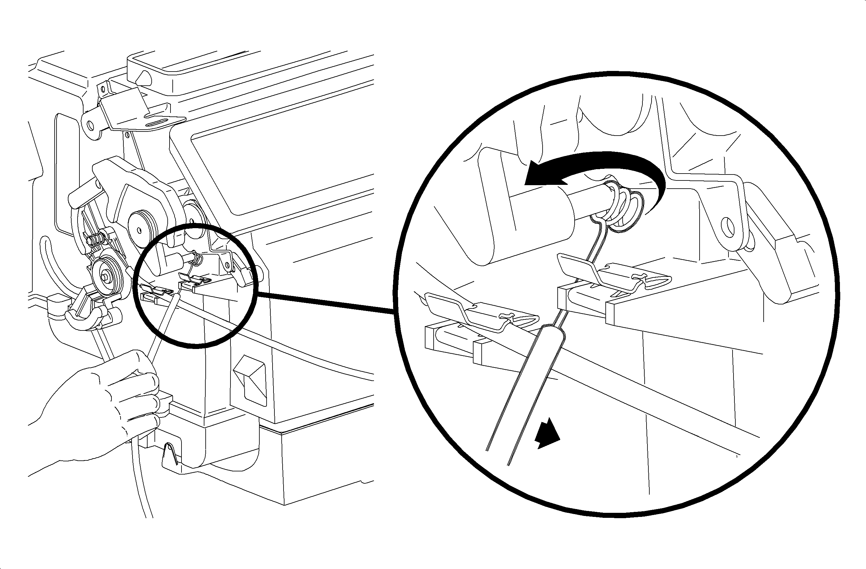
Important: Do not install the mode cable housing into the retainer at this time.
- Install the mode cable eyelet between the mode cam pin and the module case and
rotate onto the mode cam pin.

- Install the lever labeled HOT onto the lower mix cam door shaft until the tang
seats into the shaft notch.

- Install the temperature cam ensuring that the lower mix lever pin is in the
cam lower track.
- Install the temperature cam washer and screw.

- Position the lever labeled COOL onto the upper mix cam door shaft so that the
pin will be in the upper temperature cam track when seated. Press down until the
tang seats into the shaft notch.
- Rotate the temperature cam to verify the smooth operation of both doors.
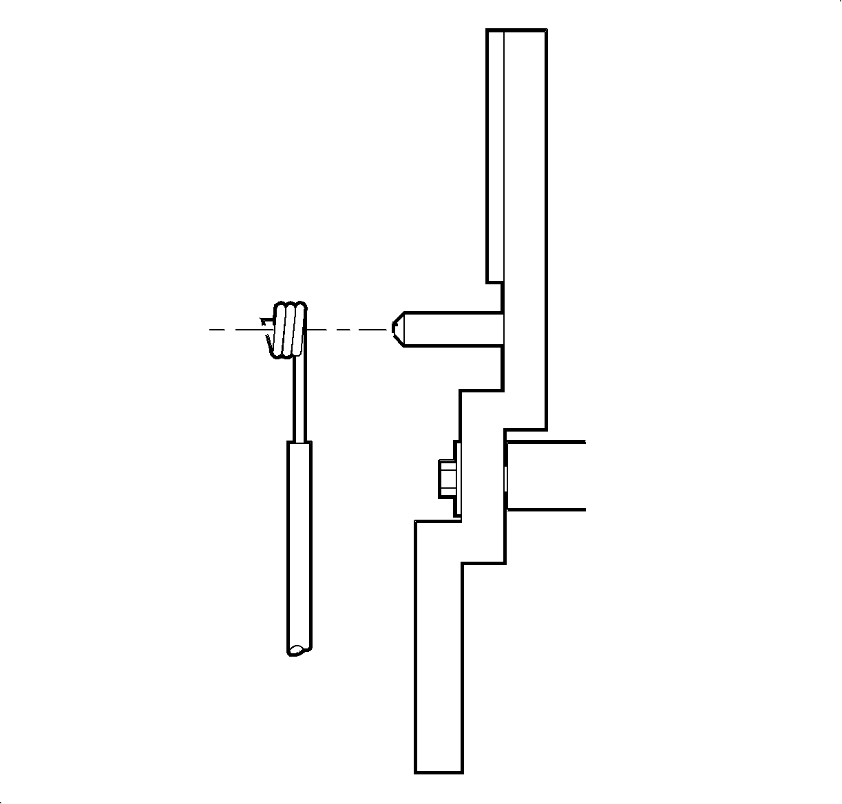
Important: Install the temperature cable with the wire eyelet wrap as shown.

Important: Do not install the temperature cable housing into the retainer clip at this
time.
- Install the temperature cable on the temperature cam pin and install the circular
push-on retainer.

- Install the left module mounting bracket and screws.

- Install the pipe support plate and screws.
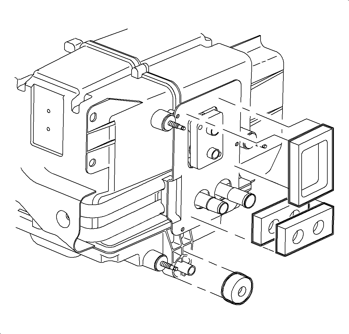
Important: The heater core pipe seal consists of 2 seals installed back to back.
- Install the evaporator block seal, the heater core pipe seal, and the drain
tube seal.
Assembly Procedure

Notice: Use only Polyalkylene Glycol Synthetic Refrigerant Oil (PAG) for internal
circulation through the R-134a A/C system and only 525 viscosity mineral oil
on fitting threads and O-rings. If lubricants other than those specified are
used, compressor failure and/or fitting seizure may result.
- Lubricate the O-rings with R-12 Refrigerant oil (mineral).
- Install the O-rings and the TXV to the HVAC module.

Important: The heater core pipes seal consists of 2 seals installed back to back.
- Install the new cowl panel seals on the heater core pipes, the case drain, and
the evaporator block.

- Install the HVAC module through the cowl.

- Install the HVAC module mounting bracket to the beam bolts, but do not tighten.

- Connect the air valve actuator electrical connector.

- Install the blower unit into the HVAC module and through the cowl.

- Install the blower unit bracket to the cowl bolt.
Tighten
Tighten the blower unit bracket-to-cowl bolt to 2.2 N·m (20 lb in).
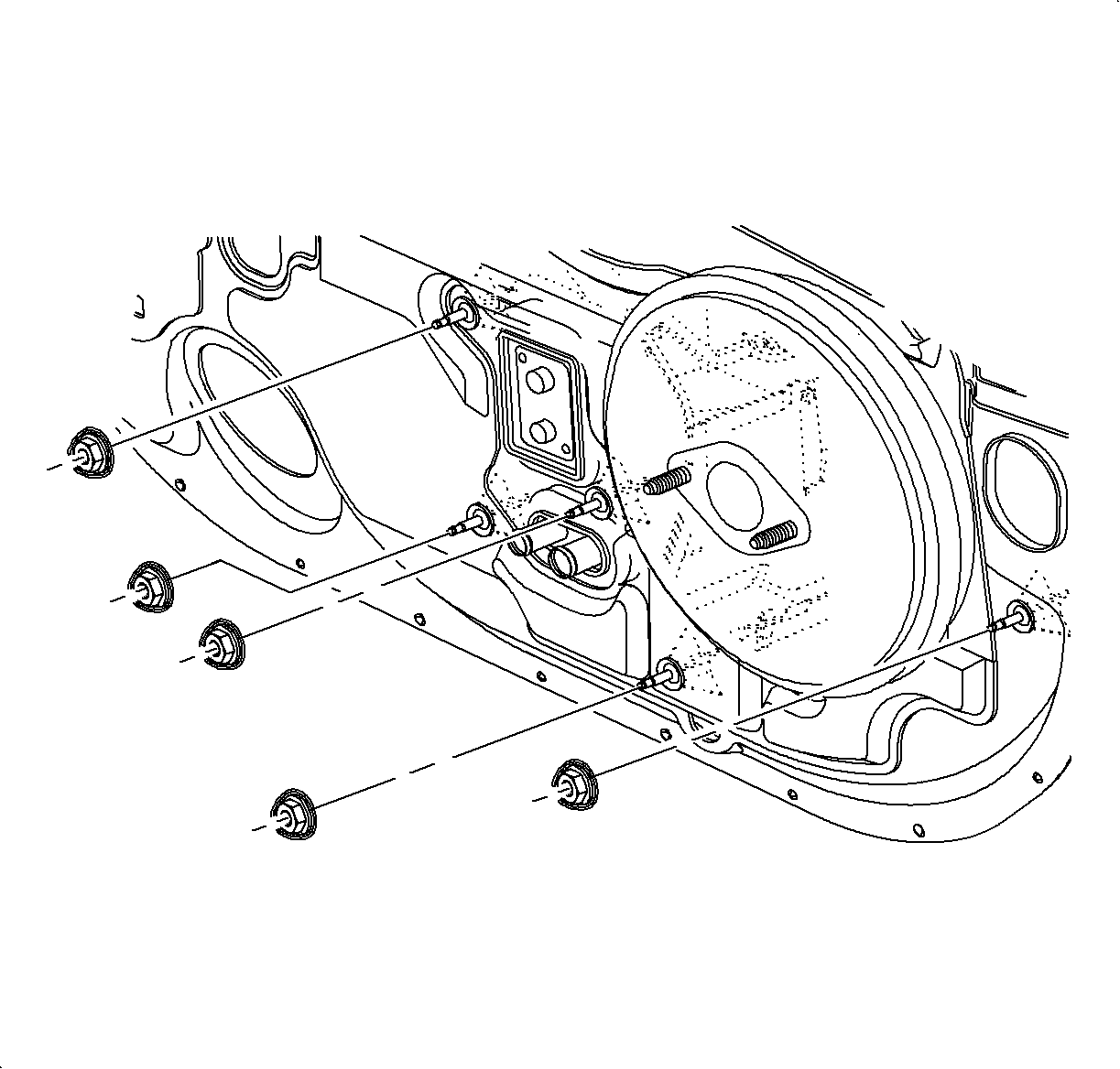
- Install the blower unit to the cowl nut at the right side of the brake booster.
Tighten
Tighten the clutch-to-compressor screws to 5 N·m (44 lb in).
Caution: Refer to Vehicle Lifting Caution in the Preface section.
- Raise the vehicle. Refer to
Lifting and Jacking the Vehicle
in General Information.
- Install the HVAC module and blower unit nuts.
Tighten
Tighten the clutch-to-compressor screws 5 N·m (44 lb in).

Important: Be careful not to push the hoses onto the heater core pipes so far that the
foam seal is contacted.
- Install the hose and the clamp on the heater core outlet. Install the clamp
at the 7-8 o'clock position.
- Install the hose and clamp on the heater core inlet. Install the clamp
at the 6 o'clock position.
- Lower the vehicle.

- Tighten the HVAC module mounting brackets to the beam bolts.
Tighten
Tighten the HVAC module-to-beam bolts to 6 N·m (53 lb in).

- Connect the blower motor electrical connector.

- Connect the blower motor resistor electrical connector.

- Install the windshield defroster nozzle onto the HVAC module and install the
screws. Make sure the duct is snapped on both sides of the HVAC module.
Tighten
Tighten the windshield defroster nozzle to 2.2 N·m (20 lb in).

- Install the center air outlet duct and screws.
Tighten
Tighten the center air outlet duct to 10 N·m (89 lb in).
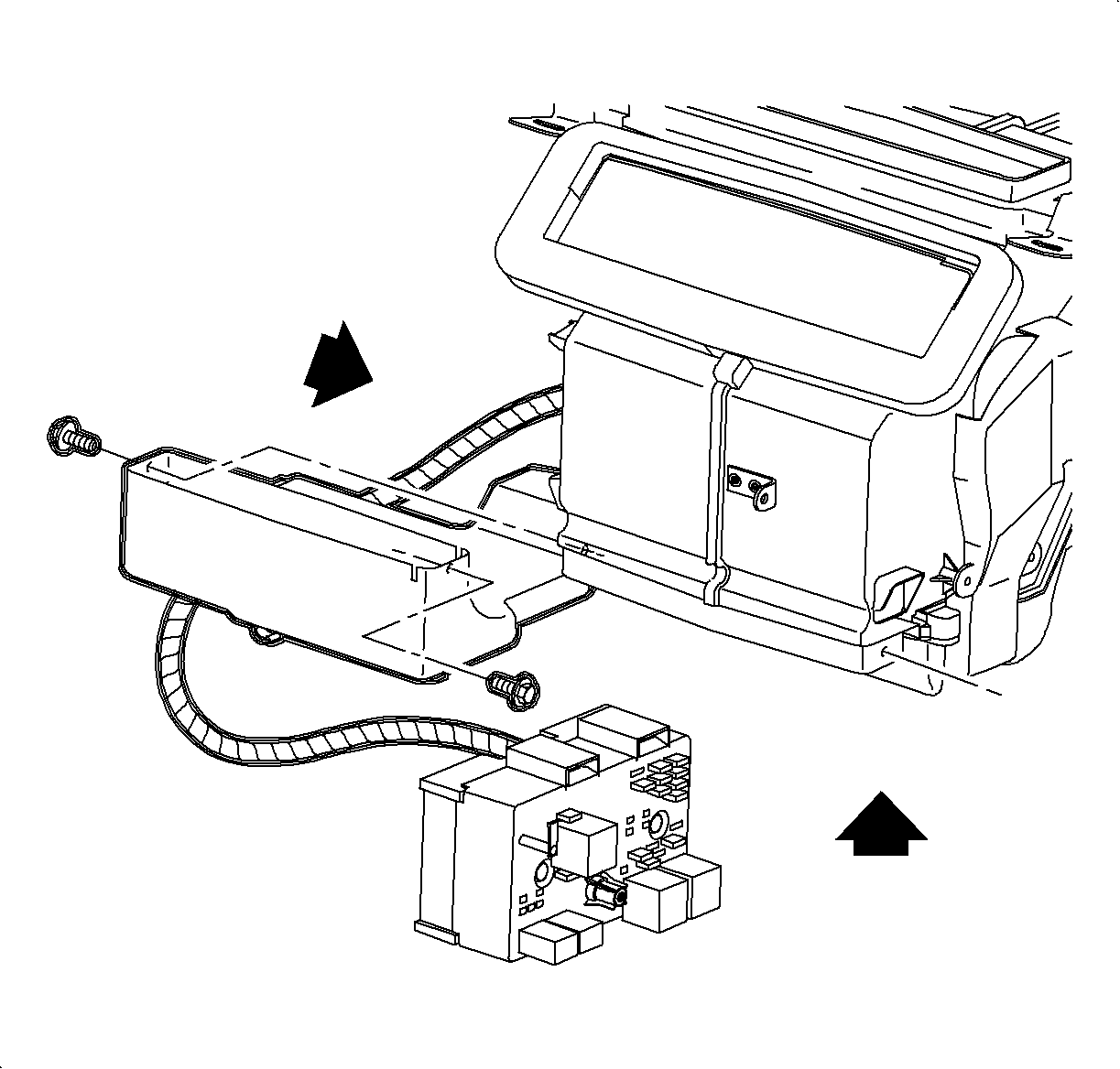
- Install the brake transaxle interrupt cable into the heater duct clamp.
Notice: Be careful not to damage foam seal.
- Install the heater duct to the HVAC module.
For Coupes: Slide the duct under the HVAC module from the left side and raise
into the installed position. Install the heater duct screws.
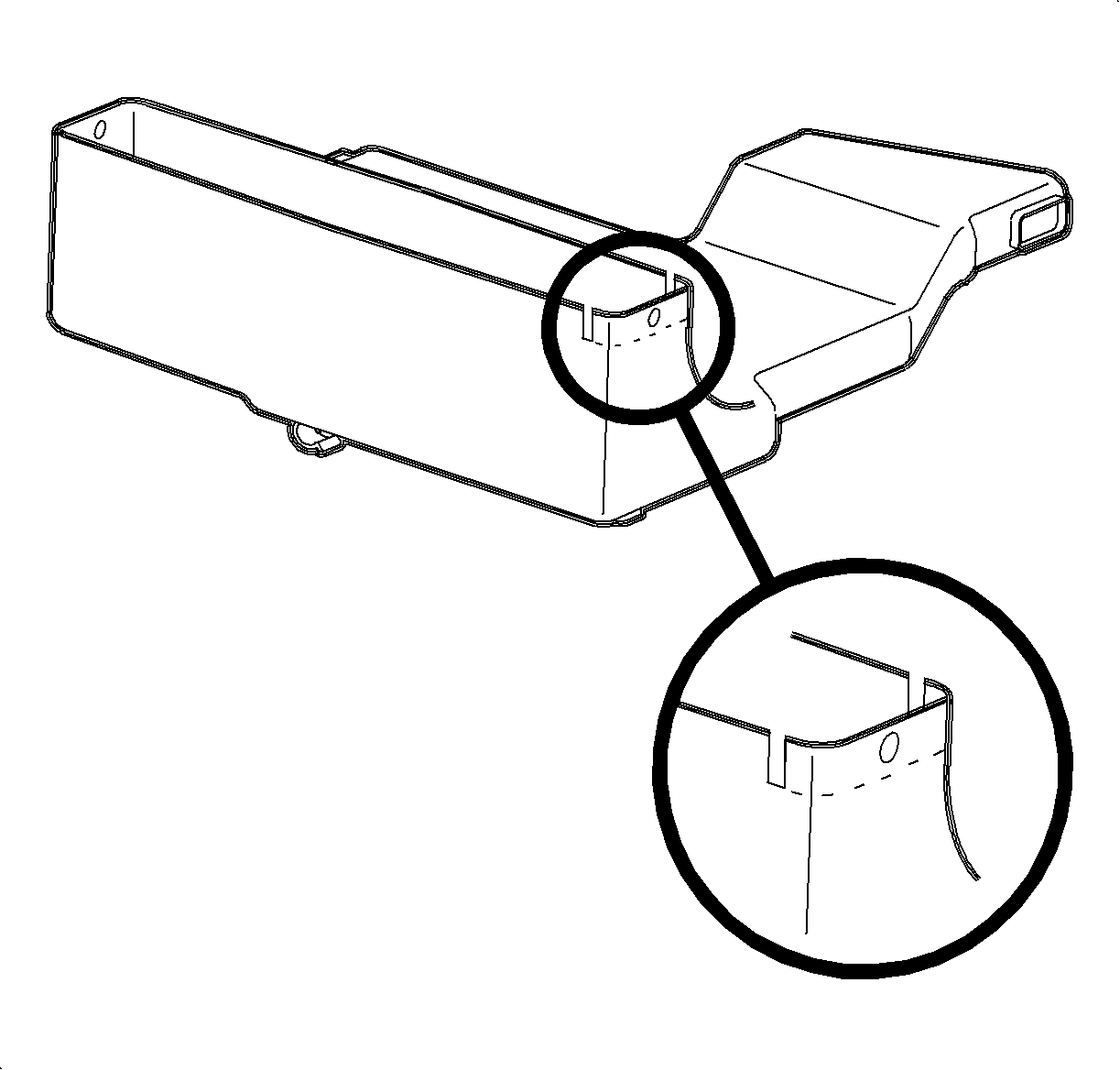
- For Sedans/Wagons: Cut the right heater duct flange off as shown, and slide
the duct into the position between the HVAC module and the rear seat heater duct.
Install the left heater duct screw.
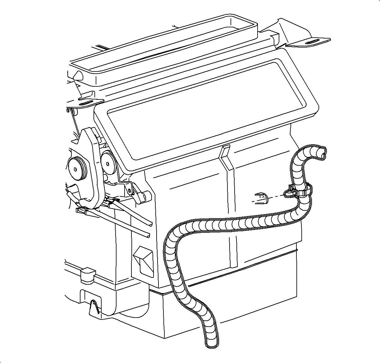
- Install the wiring harness rosebud fastener at the rear of the HVAC module.

- Install the wiring harness fastener into the side of the HVAC module.
- Install the wiring harness fastener into the left HVAC module bracket.

- Install the junction block to the H-brace.
- Install the ground wires with a screw to the H-brace.
Tighten
Tighten the ground wires-to-H-brace to 2.2 N·m (20 lb in).
- Install the radio ground strap and the screw through the H-brace to the
junction block.
Tighten
Tighten the radio ground strap-to-H-brace to 2.2 N·m (20 lb in).
- Return the I/P harness plastic retainer to the H-brace.

- Install the H-brace bolts to the front floor bracket.
Tighten
Tighten the H-brace-to-front floor bracket to 25 N·m (19 lb ft).

- Route the passenger
side inflator module harness through the retainer assembly.

- Position the inflator module in the opening in the I/P retainer assembly.
- Install the inflator module ensuring the retaining tabs are engaged to
the I/P reinforcement assembly.
- Install the 2 inflator module bolts and tighten.
Tighten
Tighten the inflator module bolts to 10 N·m (89 lb in).

- Tighten the I/P retainer assembly bolts and nuts.
Tighten
Tighten the I/P retainer assembly fasteners to 10 N·m (89 lb in).

- Install the inflator module cover.
Tighten
Tighten the inflator module cover fasteners to 2.2 N·m (20 lb in).

- Install the I/P compartment:
| 36.1. | Position the I/P compartment door assembly to the retainer assembly. |
| 36.2. | Install the I/P compartment door pins into the instrument panel retainer
assembly. |
| 36.3. | Lift the I/P compartment enough to install the I/P compartment door stop
assemblies. |
| 36.4. | Close the I/P compartment door. |

- Raise the steering column into position.
- Install and tighten the bolts.
Tighten
Tighten the steering column bolts to 35 N·m (26 lb ft).

Important: Make sure the wiring harnesses do not interfere with the control lever movement.
- Install the HVAC controller:
| 39.1. | Install the mode valve cable onto the mode valve pin. |
| 39.2. | Snap the slot on the cable into the HVAC controller base. |
| - | Temperature cable - white |
| 39.3. | Repeat the steps for the temperature cable. |

| 39.4. | Install the blower switch connector. |
| 39.5. | Install the HVAC controller harness. |
| 39.6. | Install and tighten the screws. |
Tighten
Tighten the HVAC controller-to-I/P retainer screws to 2.5 N·m (22 lb in).
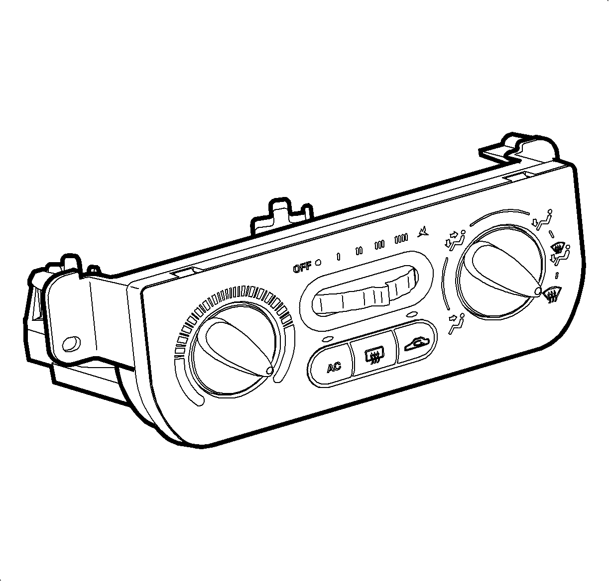
- Place the HVAC control mode knob completely to the right defroster position.
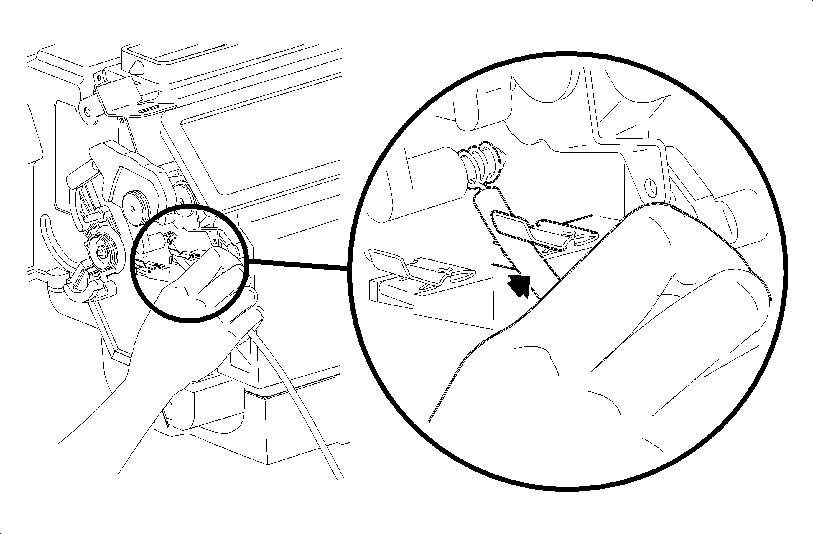
- Verify that the mode cam is still in full counterclockwise position.
- Press the mode cable housing firmly into the retainer clip to lock.
- Move the HVAC control mode knob through the modes to verify proper installation.

- Place the HVAC control temperature knob completely to the right full hot.

- Verify that the temperature cam is still in the full counterclockwise position.
- Press the temperature cable housing firmly into the retainer clip to lock.
- Move the HVAC control temperature knob from the hot to the cold to verify
proper installation.

Important: Make sure the wiring harnesses do not interfere with the control knob movement.
- Connect the blower switch, the A/C-Recirc and the lighting electrical connectors.

- Install the radio:
| 49.1. | Connect the radio ground strap spade terminal. |
| 49.2. | Connect the electrical connectors |
| 49.3. | Connect the antenna lead. |
| 49.4. | Install the radio by sliding it into the guides on the instrument panel. |
| 49.5. | Install and tighten the screws. |
Tighten
Tighten the radio-to-I/P retainer screws to 2.5 N·m (22 lb in).

- Install the I/P cluster:
| 50.1. | Place the tabs on the bottom of the I/P cluster into the retainer assembly. |
| 50.2. | Install the screws. |
Tighten
Tighten the I/P cluster retaining screws to 3 N·m (27 lb in).
| 50.3. | Connect the electrical connector to the instrument panel cluster. |

- Install the I/P cluster bezel:
| 51.1. | Pull the dimmer/traction control switch harness through the I/P cluster
bezel opening. |
| 51.2. | Position the I/P cluster bezel by lining up the clip location. |
| 51.3. | Snap the I/P cluster bezel in place by pushing at the clip locations. |

- Position the upper steering column shroud.
- Position the lower steering column shroud and install the screws.
Tighten
Tighten the steering column shroud fasteners to 1.5 N·m (13 lb in).

- Install the ignition bezel:
| 54.1. | Align the peg of the ignition bezel with the cut out in the lower shroud. |

- Connect the left and the right door jamb switch connectors.
Important: Ensure that the endcap bottom portions are inside of the filler panel and the
glovebox assemblies.
- Install the left and the right endcap assembly:
| 56.1. | Maneuver the assemblies past the inner I/P retainer assembly and weatherstrips. |
| 56.2. | Snap the clips into the I/P retainer assembly locations. |
| 56.3. | Install the screws. |
Tighten
Tighten the I/P endcap retaining screws to 2.5 N·m (22 lb in).

- Install the data link connector.
- Route the hood release cable through the I/P and then install the cable
to the lever.

- Install the steering column filler panel.
Tighten
Tighten the steering column filler panel fasteners to 2.5 N·m (22 lb in).

Notice: Be careful not to damage the VIN plate when removing or replacing the upper
trim panel.
Important: Be sure the upper trim panel seal is correctly seated on the forward edge before
installing the upper trim panel.
- Install the upper trim panel.
| 60.1. | Ensure the hook-and-loop fasteners on the upper trim panel are correctly
inserted. |
| 60.2. | Position the upper trim panel on the retainer assembly. |
| 60.3. | Align the tabs on the sides of the upper trim panel with the openings
in the windshield garnish molding. |
| 60.4. | Align the clips and the clip location. |
| 60.5. | Firmly snap in the clips at the clip locations. |
| 60.6. | Install the screws on the underside of the upper trim panel on the passenger's
side of the vehicle. |
Tighten
Tighten the I/P upper trim panel fastener to 6 N·m (53 lb in).

- Install the console:
| 61.1. | Apply the park brake. |
| 61.2. | Adjust the front seats to the most rearward position. |
| 61.3. | Recline the driver's and the passenger's seatbacks as far down as possible. |
| 61.4. | Select neutral for the transaxle gear on automatic transaxles. |
| 61.5. | Hold the front end of the console down and the rear end up. |
| 61.6. | Position all the harnesses so they can be accessed. |
| 61.7. | Maneuver the console over the gear selector lever and past the brake lever. |
| 61.8. | Connect the power outlet electrical connector. |

| 61.9. | On automatic transaxle equipped vehicles, remove the tape from the gear selector. |
| 61.10. | Install the screws at the rear of the console. |
Tighten
Tighten the rear console screws to 2.5 N·m (22 lb in).

| 61.11. | Install and tighten the front console screws. |
Tighten
Tighten the front console screws to 2.5 N·m (22 lb in).

| 61.12. | Install the left and the right extension panels by inserting the hinges into
the console. |
| 61.13. | Rotate and push in at the dual lock locations. |

- Connect the window switch assembly connector, if equipped.
- Install the window switch assembly or the storage tray, depending on the
equipment.
Caution: Refer to Vehicle Lifting Caution in the Preface section.

- Raise the vehicle. Refer to
Lifting and Jacking the Vehicle
in General Information.
Important: Be careful not to push the hoses onto the heater core so far that the foam seal
is unseated.
- Install the hose and the clamp on the heater core outlet. Position the clamp
at a 7-8 o'clock position.

- Install the hose and the clamp on the heater core inlet. Position the clamp
at a 6 o'clock position.

- Lower the vehicle.
Notice: Use only Polyalkylene Glycol Synthetic Refrigerant Oil (PAG) for internal
circulation through the R-134a A/C system and only 525 viscosity mineral oil
on fitting threads and O-rings. If lubricants other than those specified are
used, compressor failure and/or fitting seizure may result.
- Remove the protective covers. Lubricate with R-12 Refrigerant
oil (mineral) and install the new O-rings on the evaporator pipes.
- Install the thermal expansion valve (TXV) on the evaporator.
Tighten
Tighten the thermal expansion valve (TXV)-to-evaporator to 10 N·m
(89 lb in).

Notice: Use only Polyalkylene Glycol Synthetic Refrigerant Oil (PAG) for internal
circulation through the R-134a A/C system and only 525 viscosity mineral oil
on fitting threads and O-rings. If lubricants other than those specified are
used, compressor failure and/or fitting seizure may result.
- Lubricate the O-rings with R-12 Refrigerant oil (mineral)
and install the new O-rings on the suction hose and the liquid line.
- Install the liquid line on the TXV.
Tighten
Tighten the liquid line-to-TXV to 25 N·m (19 lb ft).
- Install the suction hose on the TXV.
Tighten
Tighten the suction hose-to-TXV to 25 N·m (19 lb ft).

- Install the air cleaner housing cover and the air induction hose.
- Fill and pressure test the cooling system.
- Evacuate, charge, and leak test the A/C system. Perform the A/C Performance
Test.
- Connect the negative battery cable.
Tighten
Tighten the negative battery cable to 17 N·m (13 lb ft).
- Set the clock to the proper time, if equipped.
- Enable the SIR system. Refer to
Enabling the SIR System
in SIR.
- Reset the radio stations.


