- Lower the valve body into the case and insert the manual link into the manual valve.
- Install and finger tighten the valve body-to-case dowel bolts first. This procedure must be followed to ensure the valve body is properly aligned to the case. For reference, the bolts are identified as follows:
- Clean and lubricate the fasteners with Saturn Transaxle Fluid. Wipe off excess fluid and install.
- Tighten the valve body-to-case bolts using tightening sequence shown in the illustration.
- Verify the location of the valve body bolts
- Clean the transaxle case and the valve body cover sealing surfaces with Saturn Choke and Brake Cleaner or equivalent, applied with a clean shop towel.
- Align the valve body cover gasket on the valve body cover and install on the transaxle case.
- When installing the valve body cover, ensure to properly tighten the valve body cover bolts using the tightening sequence shown.
- Verify tightening of the valve body cover bolts to account for gasket relaxation using the tightening sequence shown.
- Install and tighten the master cylinder-to-booster nuts.
- Install and tighten the ABS mid-rail bracket bolt.
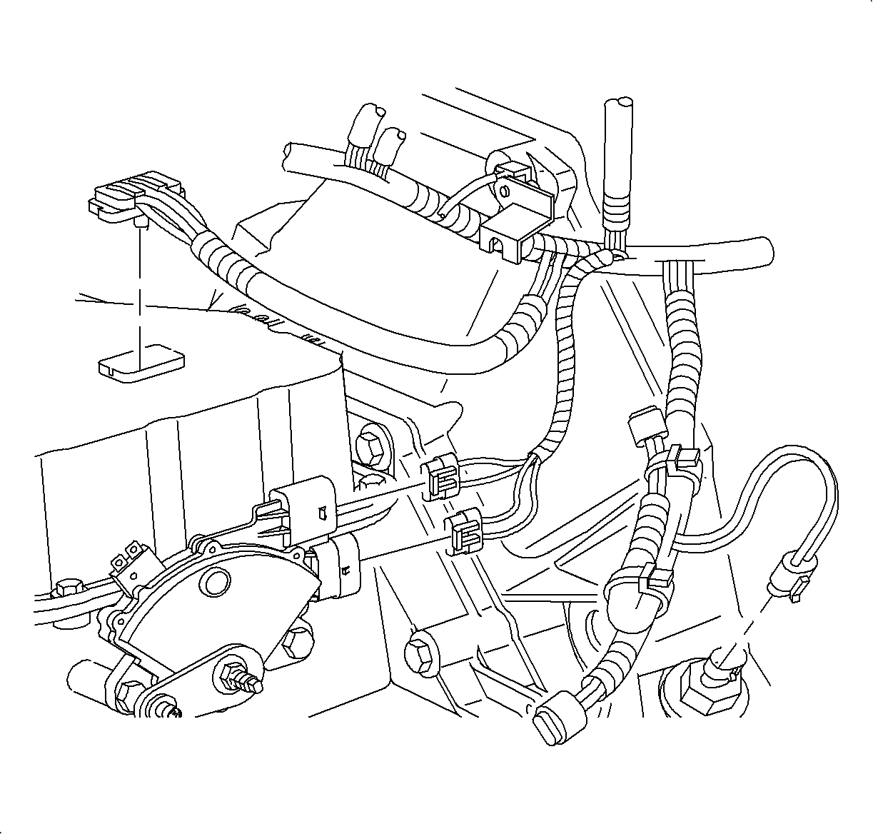
- Connect the transaxle solenoid harness connector.
- Install the transaxle connector bolt.
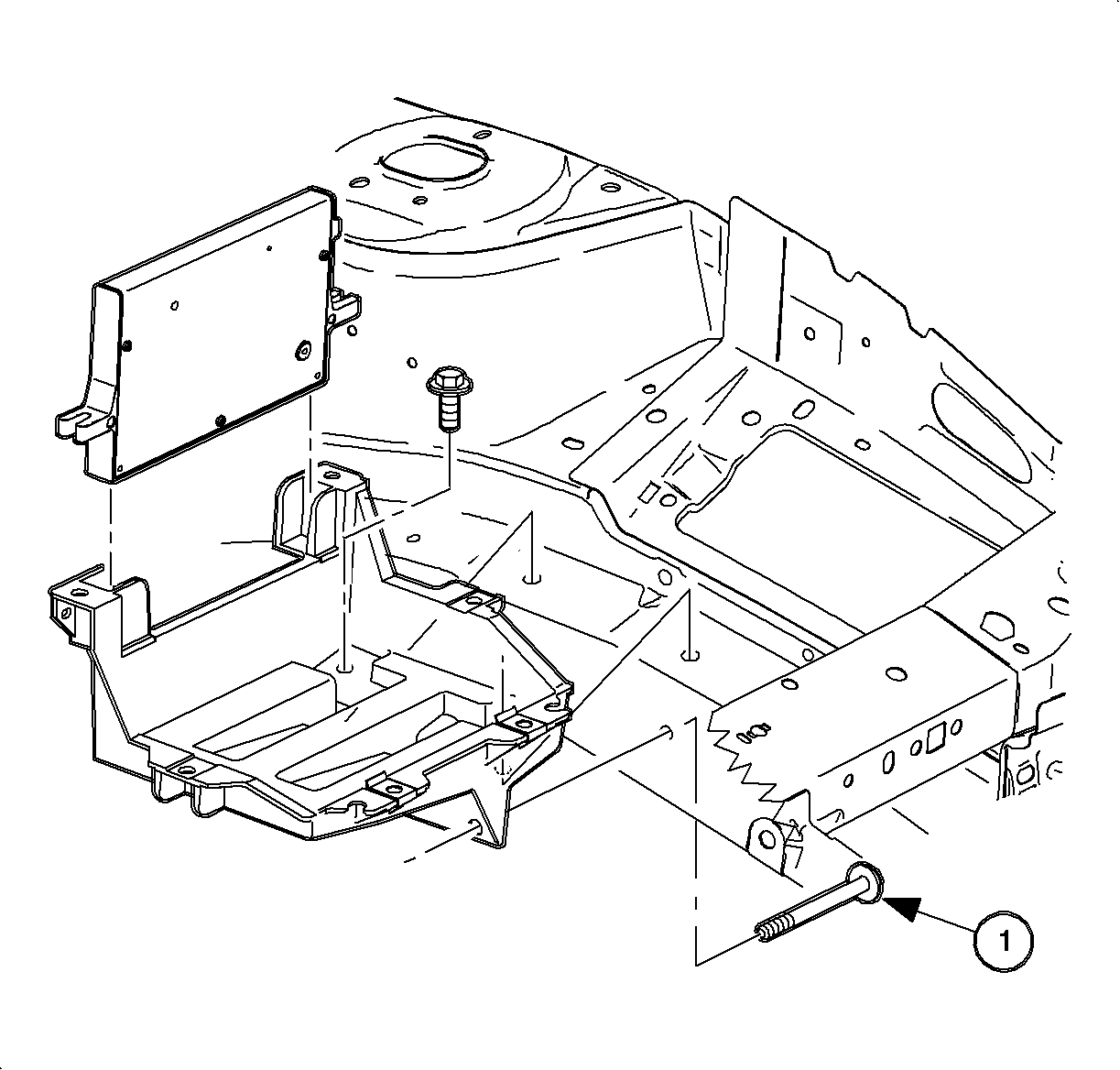
- Install the battery tray.
- Install the battery tray bolts.
- One bolt is located in the fender well.
- Install the powertrain control module (PCM) and attachment bolts.
- Connect the PCM J2 black 28-way connector and engage the locking device.
- Ensure the battery tray is clean.
- Ensure the battery cable ends are clean and free of corrosion. Clean with a wire brush.
- Ensure the battery is in good physical condition (e.g., no cracks, or obvious damage) and the terminals are clean.
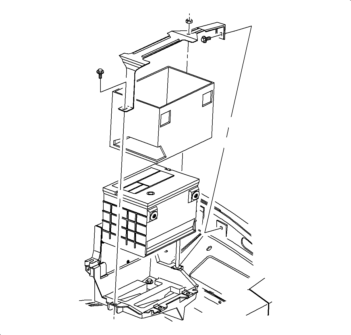
- Install the battery carefully in the battery tray; ensure the terminals do not short against any metal during installation.
- Install the battery hold-down retainer, locking the battery into the tray. Install and tighten the hold-down retainer nut and screws.
- Install the positive battery cable first.
- Install the negative battery cable last.
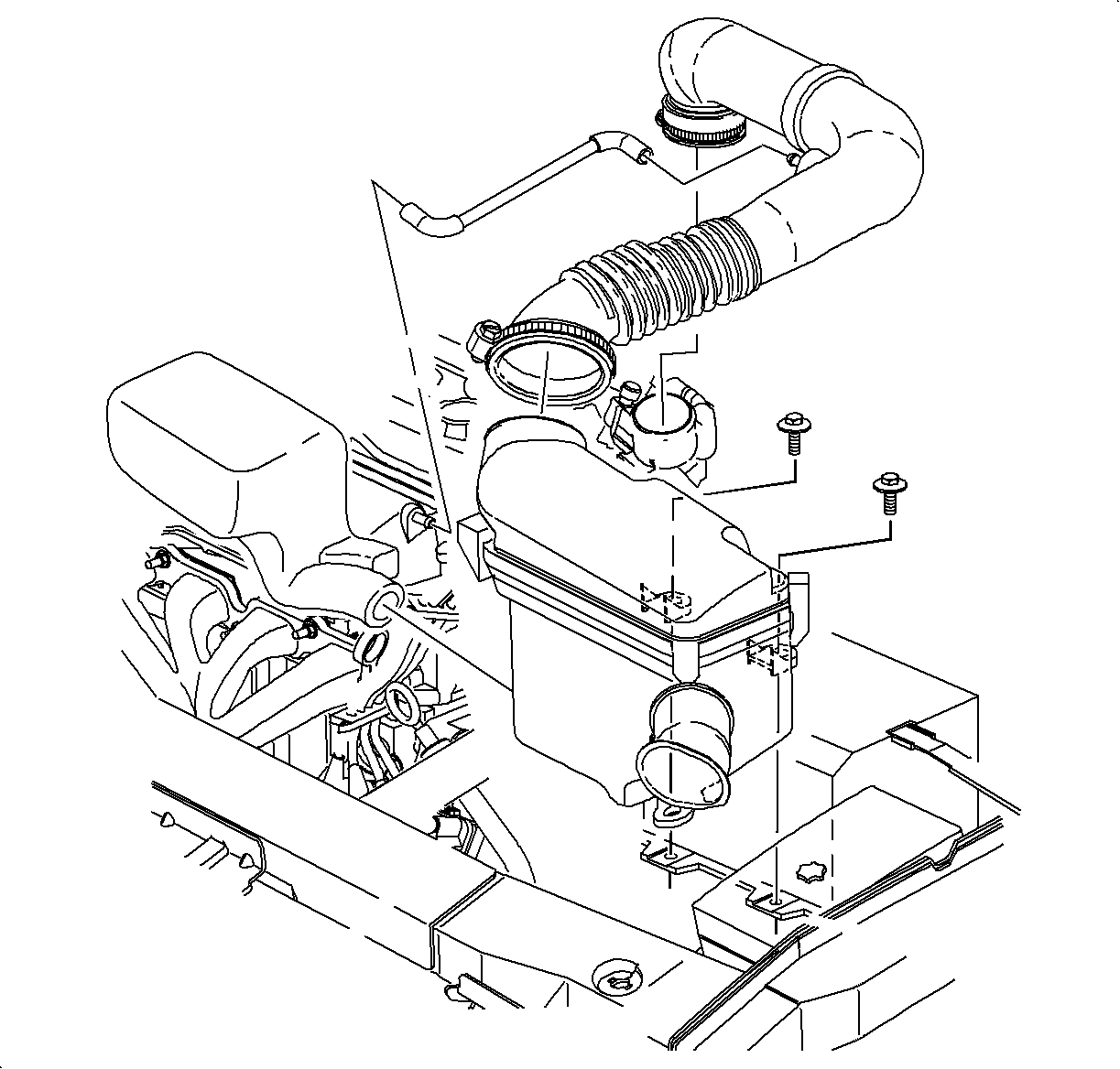
- Install the air cleaner and duct assembly. Refer to Air Cleaner Housing and Duct Assembly Replacement .
- Set the clock.
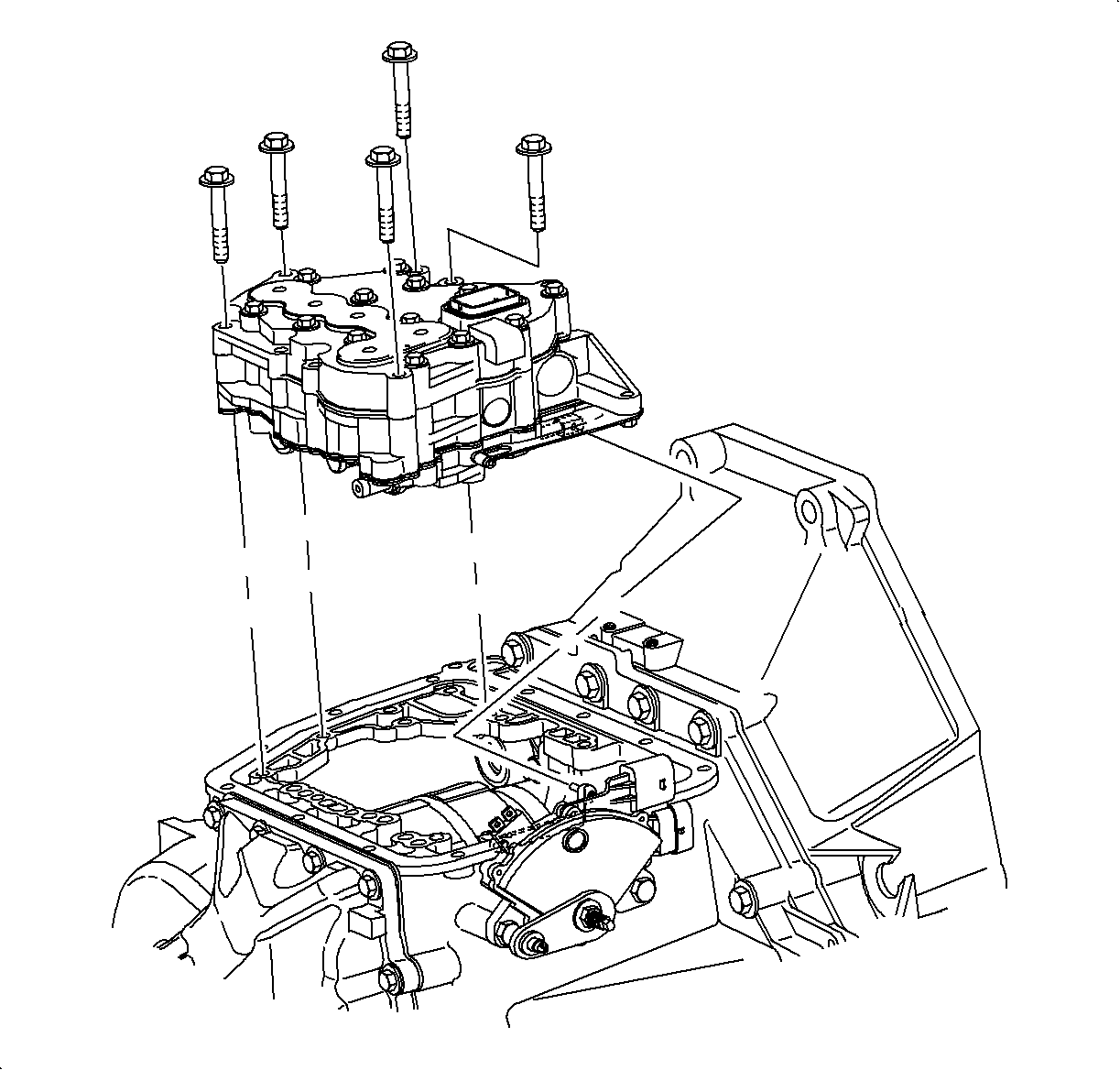
Important: The valve body-to-case bolts must be placed in the valve body prior to installation.
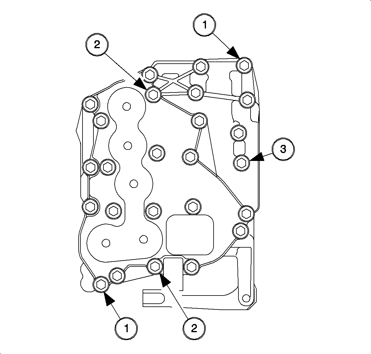
| • | The valvebody-to-case dowel bolts |
| • | The upper-to-lower valvebody dowel bolts |
| • | The bolt holding upper and lower valve body |
Notice: Refer to Fastener Notice in the Preface section.
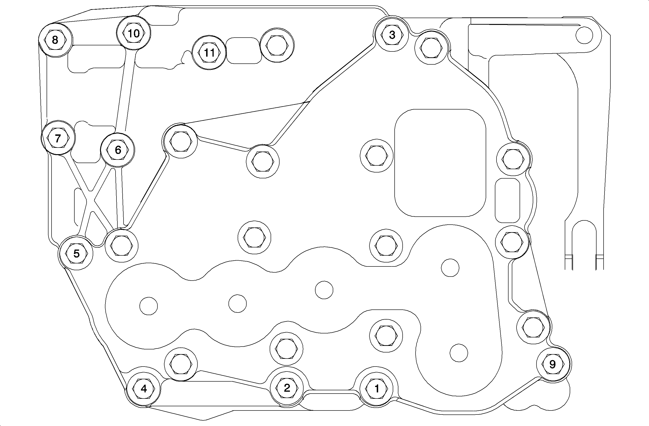
Notice: Over-torqueing bolts can cause valves to bind.
Tighten
Tighten the valve body assembly bolts to 11 N·m (8 lb ft).
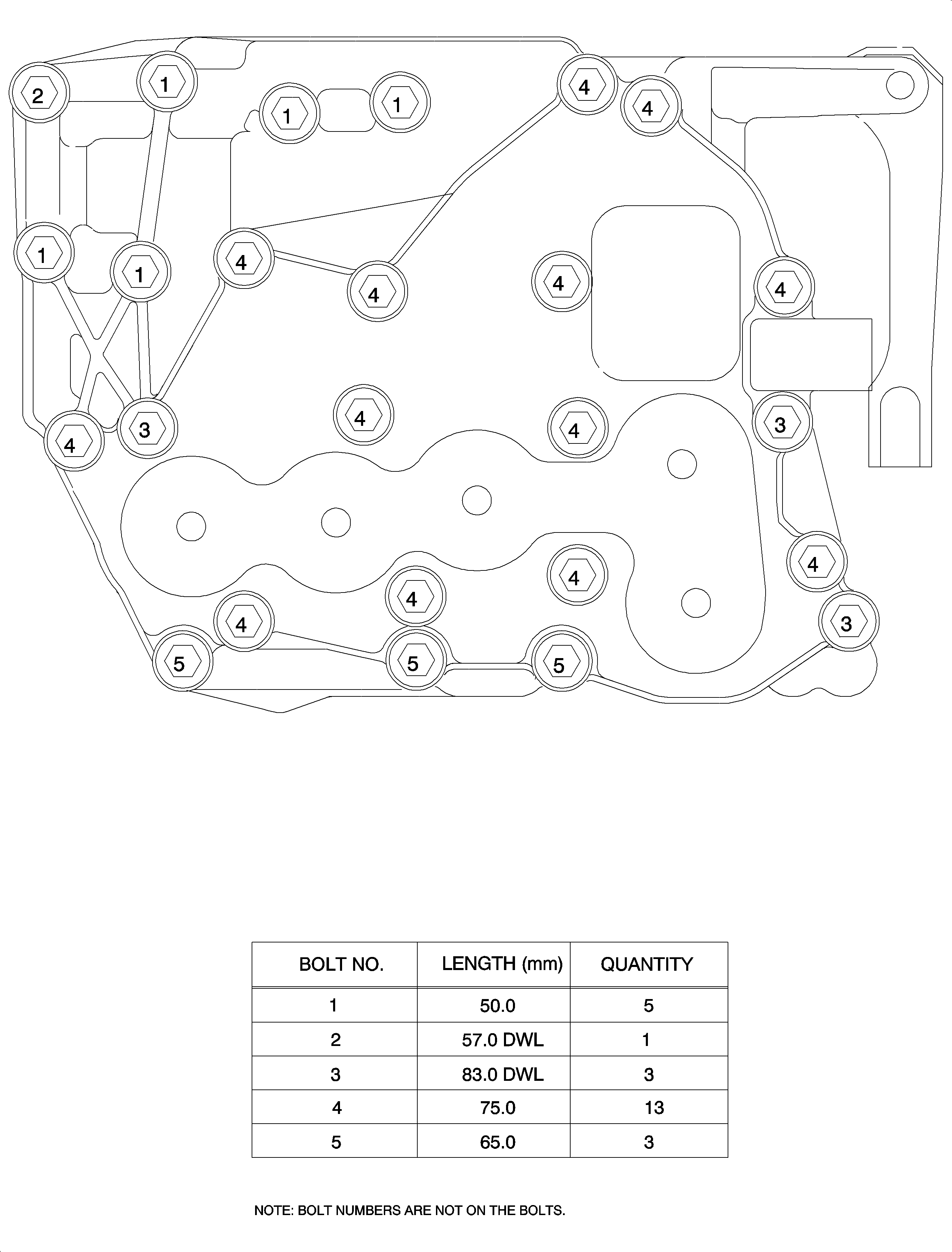
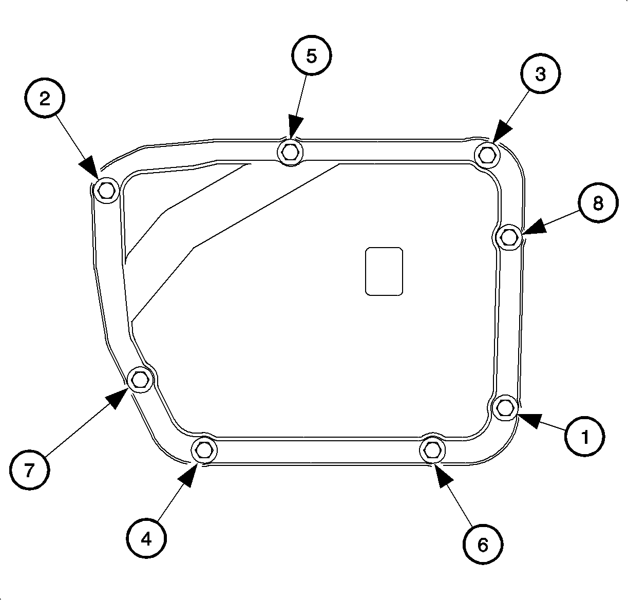
Important: Install the new gasket during reassembly.
Important: Clean and lubricate the fasteners with Saturn Transaxle Fluid. Wipe off excess fluid.
Tighten
Tighten the valvebody cover-to-case bolts to 12 N·m (9 lb ft).
Tighten
Tighten the valve body cover-to-case bolts to 12 N·m (9 lb ft).
Tighten
Tighten the brake master cylinder-to-booster nuts to 27 N·m (20 lb ft).
Tighten
Tighten the anti-lock brake system (ABS) bracket-to-midrail bolt to 16 N·m
(9 lb ft).
Notice: Do not over-tighten or damage to the connector plate may occur.
Tighten
Tighten the transaxle electrical connector bolt to 3 N·m (27 lb in).
Tighten
Tighten the battery tray-to-frame rail bolts to 10 N·m (89 lb in).
Tighten
Tighten the PCM-to-battery tray bolts to 6 N·m (53 lb in).
Tighten
Tighten the battery case bracket stud and nut to 9 N·m (80 lb in).
Tighten
Tighten the battery terminal bolts to 17 N·m (13 lb ft).
Tighten
Tighten the battery terminal bolts to 17 N·m (13 lb ft).
