| Table 1: | Relay Cavity Identification |

Circuit Description
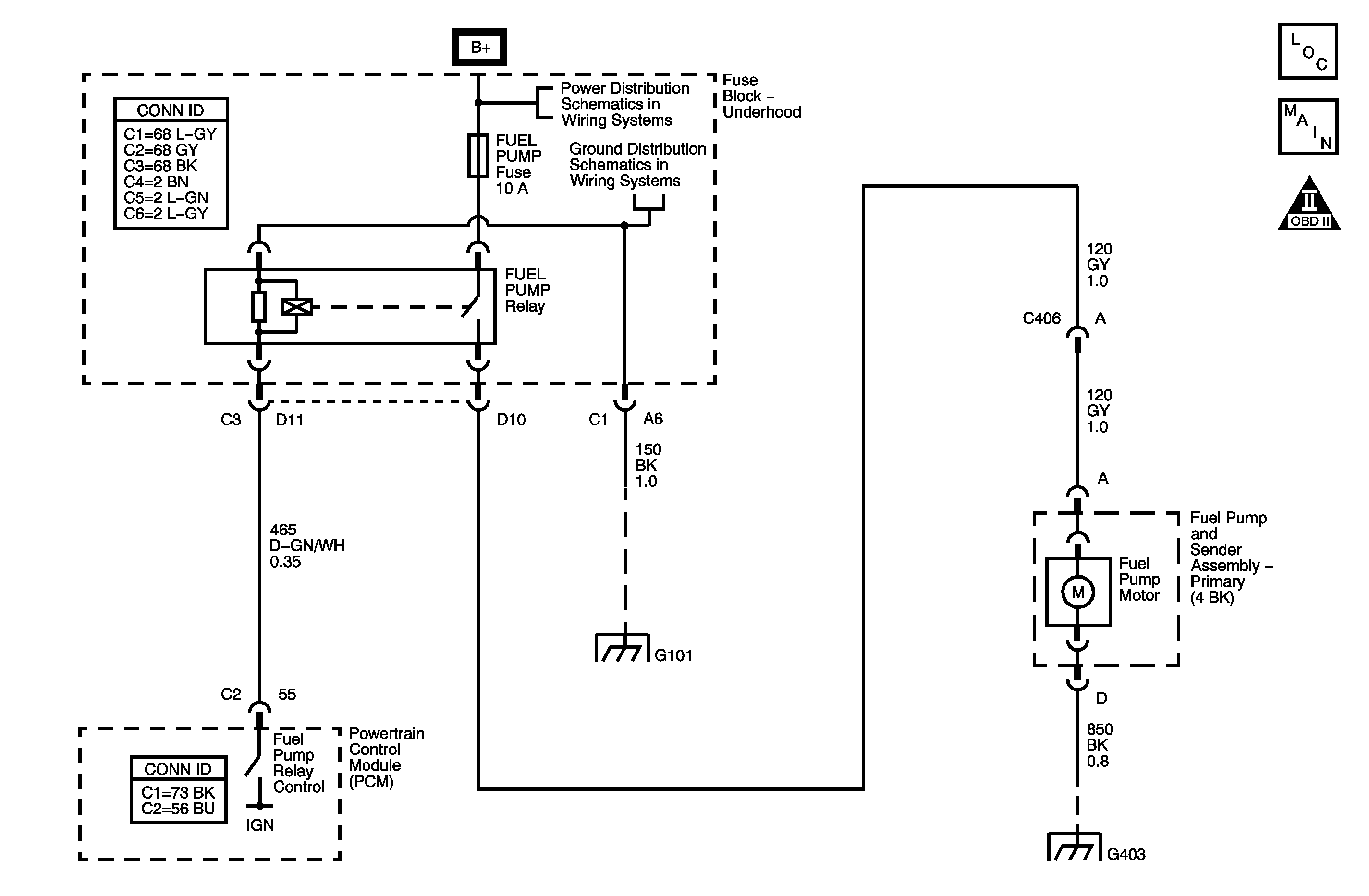
The DTC P0629 Fuel Pump Relay Control Circuit High Voltage diagnostic detects an incorrect voltage on the coil control circuit. The fuel pump relay, is controlled by the powertrain control module (PCM). The PCM energizes the relay coil for 2 seconds when the ignition switch is first turned ON and when ignition system reference pulses are detected. The fuel pump relay supplies ignition positive voltage to the fuel pump.
DTC Descriptor
This diagnostic procedure supports the following DTC.
DTC P0629 Fuel Pump Relay Control Circuit High Voltage
Conditions for Running the DTC
| • | Battery voltage is 10.5 volts or more. |
| • | DTC P0629 runs continuously with the above condition met. |
Conditions for Setting the DTC
| • | The PCM detects a higher than expected voltage on the coil control circuit . |
| • | The above condition is present for at least 1 second. |
Action Taken When the DTC Sets
| • | The PCM illuminates the malfunction indicator lamp (MIL) the first time the diagnostic fails. |
| • | The PCM records the operating conditions at the time the diagnostic fails. This information is stored in the Freeze Frame buffer. |
Conditions for Clearing the MIL/DTC
| • | The MIL turns OFF after 3 consecutively passing trips without a fault present. |
| • | A history DTC clears after 40 consecutive warm-up cycles without a fault. |
| • | Perform the scan tool Clear DTC Information function. |
Diagnostic Aids
Check for any of the following conditions:
| • | Check the resistance of the relay. The resistance across the coil terminals is 70-95 ohms at 20°C (68°F). The resistance across the switched terminals is infinite. |
| • | The relay electrical contacts may be pitted or sticking. Replace the relay if tapping gently on the relay or wiggling the relay causes a change in the relays operation. |
| • | The performance of the relay may be affected by temperature. Test the relay after sitting outside overnight and after running the engine 30 minutes. |
An intermittent malfunction may be caused by a fault in the relay electrical circuit. Inspect the wiring harness and components for an intermittent condition. Refer to Intermittent Conditions .
Use the following relay cavity table in order to locate the correct cavities to probe during diagnosis. The table layout corresponds to the cavity layout of the relay block.
Front of Vehicle | |
Switch Load | Battery Power Coil |
Coil Control | Battery Power Load |
Test Description
The numbers below refer to the step numbers on the diagnostic table.
-
This step verifies that the control module is providing voltage to the fuel pump relay.
-
This step tests for an open in the ground circuit to the fuel pump relay.
Step | Action | Yes | No |
|---|---|---|---|
Connector End View Reference: Powertrain Control Module Connector End Views or Engine Controls Connector End Views | |||
1 | Did you perform the Diagnostic System Check-Engine Controls? | Go to Step 2 | |
2 |
Does the fuel pump relay turn ON and OFF with each command? | Go to Step 3 | Go to Step 4 |
3 |
Did the DTC fail this ignition? | Go to Step 4 | Go to Diagnostic Aids |
Does the test lamp turn ON and OFF when commanded? | Go to Step 5 | Go to Step 6 | |
Does the test lamp turn ON and OFF when commanded? | Go to Step 7 | Go to Step 9 | |
6 | Test the control circuit of the fuel pump relay for a short to voltage or an open. Refer to Circuit Testing and Wiring Repairs Circuit in Wiring Systems. Did you find and correct the condition? | Go to Step 12 | Go to Step 8 |
7 | Test for shorted terminals and for poor connections at the fuel pump relay. Refer to And in Wiring Systems. Did you find and correct the condition? | Go to Step 12 | Go to Step 10 |
8 | Test for shorted terminals and for poor connections at the ECM. Refer to Testing for Intermittent Conditions and Poor Connections and Connector Repairs in Wiring Systems. Did you find and correct the condition? | Go to Step 12 | Go to Step 11 |
9 | Repair the open ground circuit of the fuel pump relay. Refer to Wiring Repairs in Wiring Systems. Did you complete the repair? | Go to Step 12 | -- |
10 | Replace the fuel pump relay. Did you complete the replacement? | Go to Step 12 | -- |
11 |
Did you complete the replacement? | Go to Step 12 | -- |
12 |
Did the DTC fail this ignition? | Go to Step 2 | Go to Step 13 |
13 | Observe the Capture Info with a scan tool. Are there any DTCs that have not been diagnosed? | System OK | |
