Caution: Do not allow smoking or the use of open flames in the area where work on the
fuel or EVAP system is taking place. Anytime work is being done on the
fuel system, disconnect the negative battery cable, except for those tests where battery
voltage is required.
- Ensure that the fuel level in the tank is less than 1/4 full. If necessary, drain the fuel tank to at least this level. Refer to
Fuel Tank Draining
.
Caution: Fuel supply lines will remain pressurized for long periods of time after the
engine is shutdown. This pressure must be relieved before servicing the fuel system.
- Relieve the fuel system pressure. Refer to
Fuel Pressure Relief
.
- Disconnect the negative battery cable. Refer to
Battery Negative Cable Disconnection and Connection
.
- Raise and support the vehicle . Refer to
Lifting and Jacking the Vehicle
.

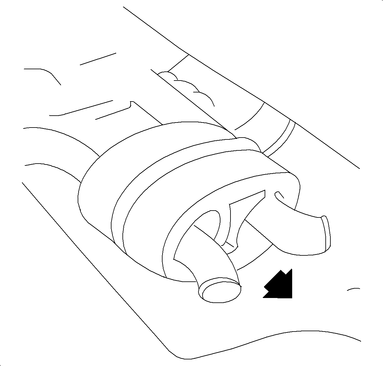
- Remove the rubber exhaust hangers on order to allow the exhaust system to drop slightly.
- Remove the propeller shaft, if equipped. Refer to
Propeller Shaft Replacement
.

Notice: Clean all fuel pipe connections and surrounding areas before disconnecting the
fuel pipes to avoid contamination of the fuel system.
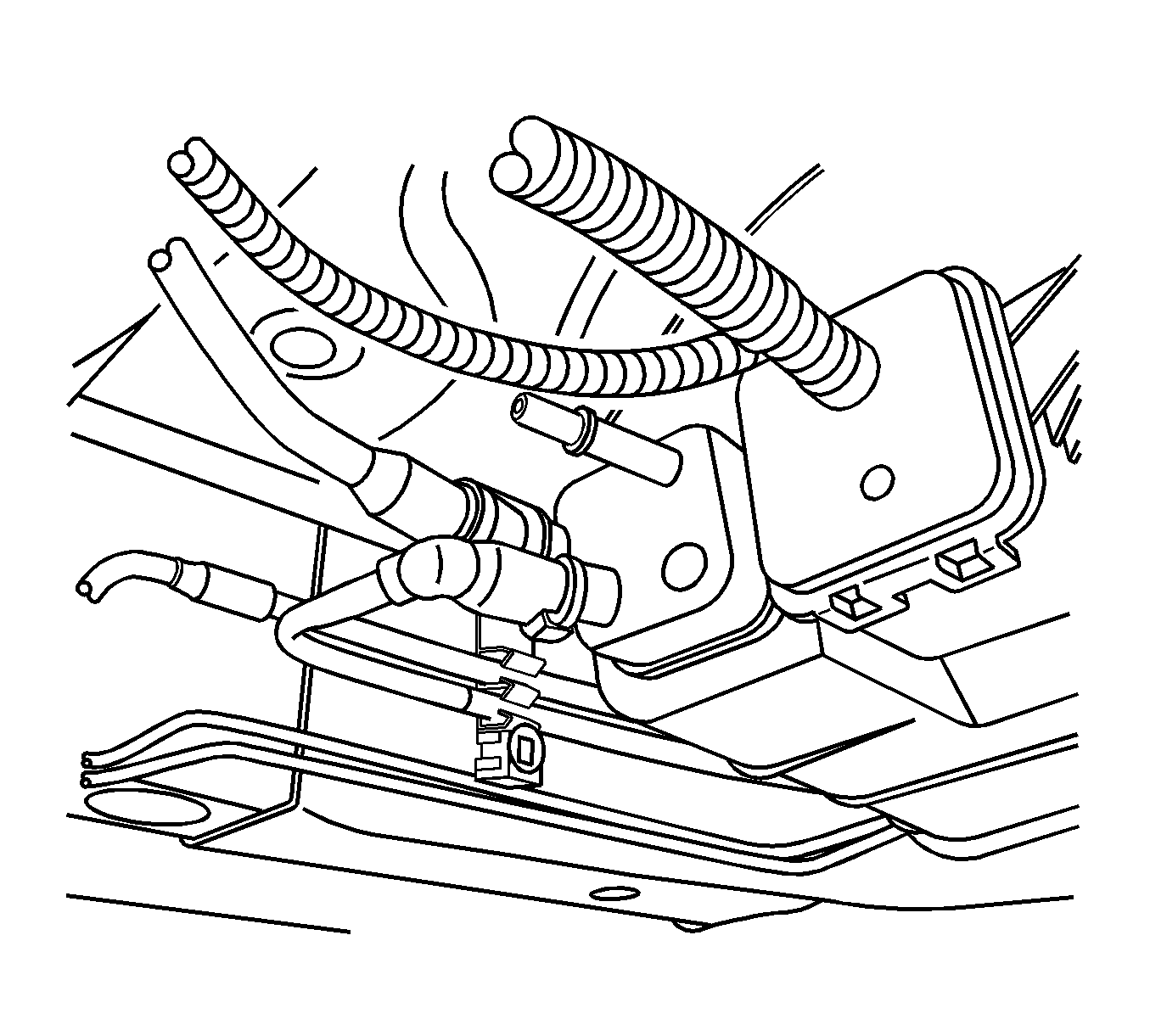
- Disconnect the EVAP canister vent and fresh air hoses:
| 7.1. | Grasping both sides of the quick-connect fitting, twist the female connector 1/4 turn in each direction in order to loosen dirt within the quick-connect fitting. |
| 7.2. | Blow any dirt out of the quick-connect fitting using compressed air. |
| 7.3. | Squeeze the plastic retainer release tabs. |
| 7.4. | Pull the connection apart. |
| 7.5. | Inspect both ends of the quick-connect fitting for dirt and burrs. |

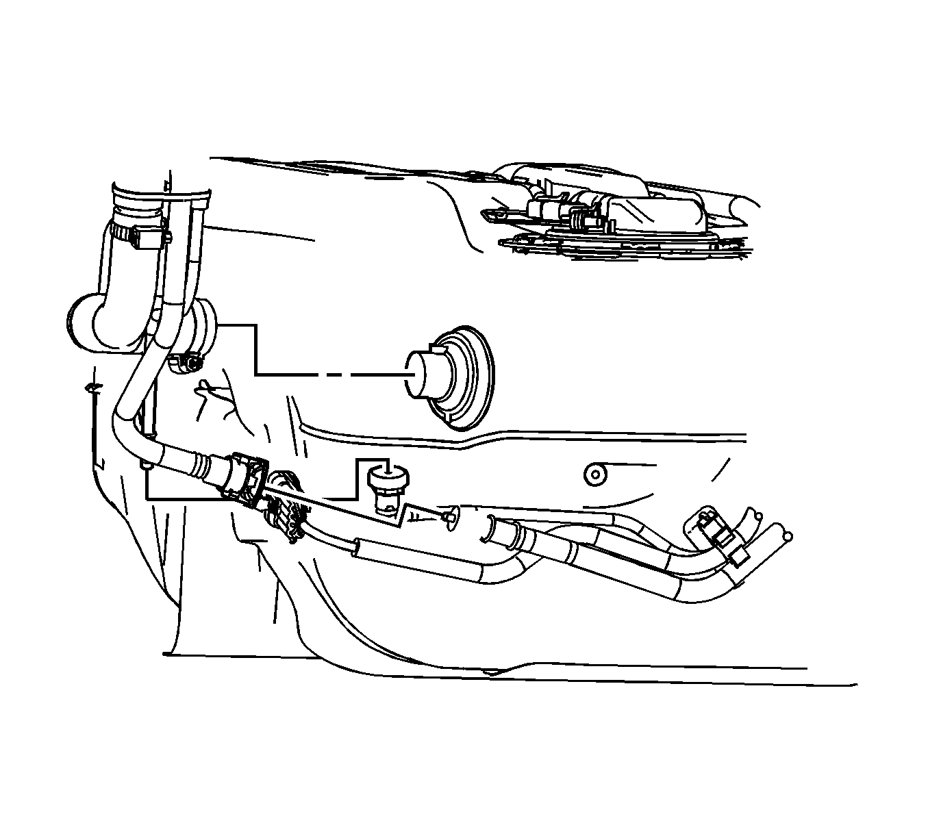
- Remove the fuel filler pipe, EVAP vent hose, and fresh air hose from the fuel tank.
Caution: Whenever fuel lines are removed, catch fuel in an approved
container. Container opening must be a minimum of 300 mm (12
in) diameter to adequately catch the fluid.
- Disconnect the chassis fuel supply line from the tank.
- Disconnect the electrical connectors:
| 10.1. | Fuel tank electrical connectors |
| 10.2. | EVAP solenoid electrical connector |

Notice: Do not bend the fuel tank straps. Bending the fuel tank straps may cause damage
to the straps.
Important: Do not disassemble the RDM. It is not necessary to touch the RDM for fuel tank removal.
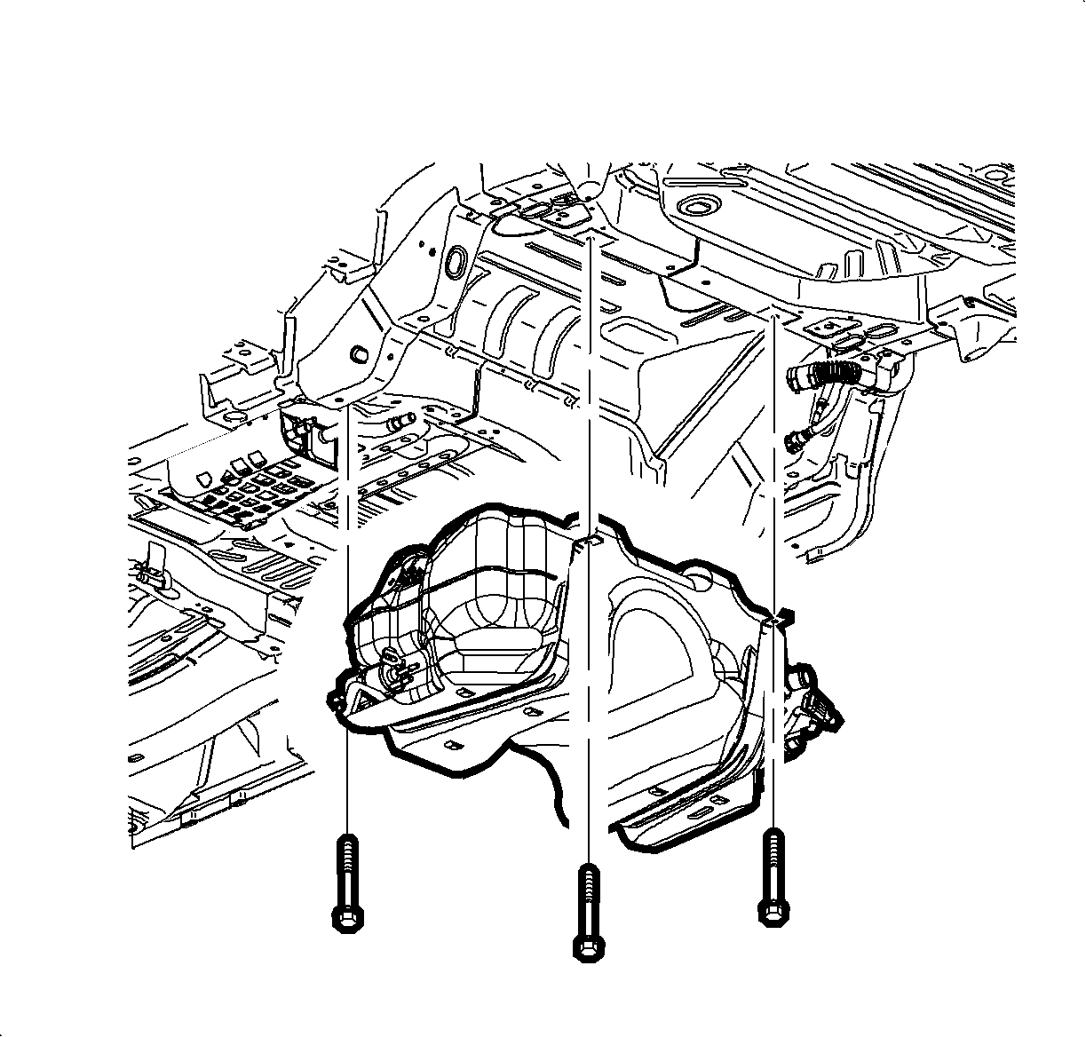
- Support the fuel tank.
- Remove the fuel tank strap bolts and fuel tank straps.
- Lower the fuel tank from the underbody of the vehicle.
- Remove the fuel tank module assemblies. Refer to
Primary Fuel Tank Module Replacement
and
Secondary Fuel Tank Module Replacement
.


