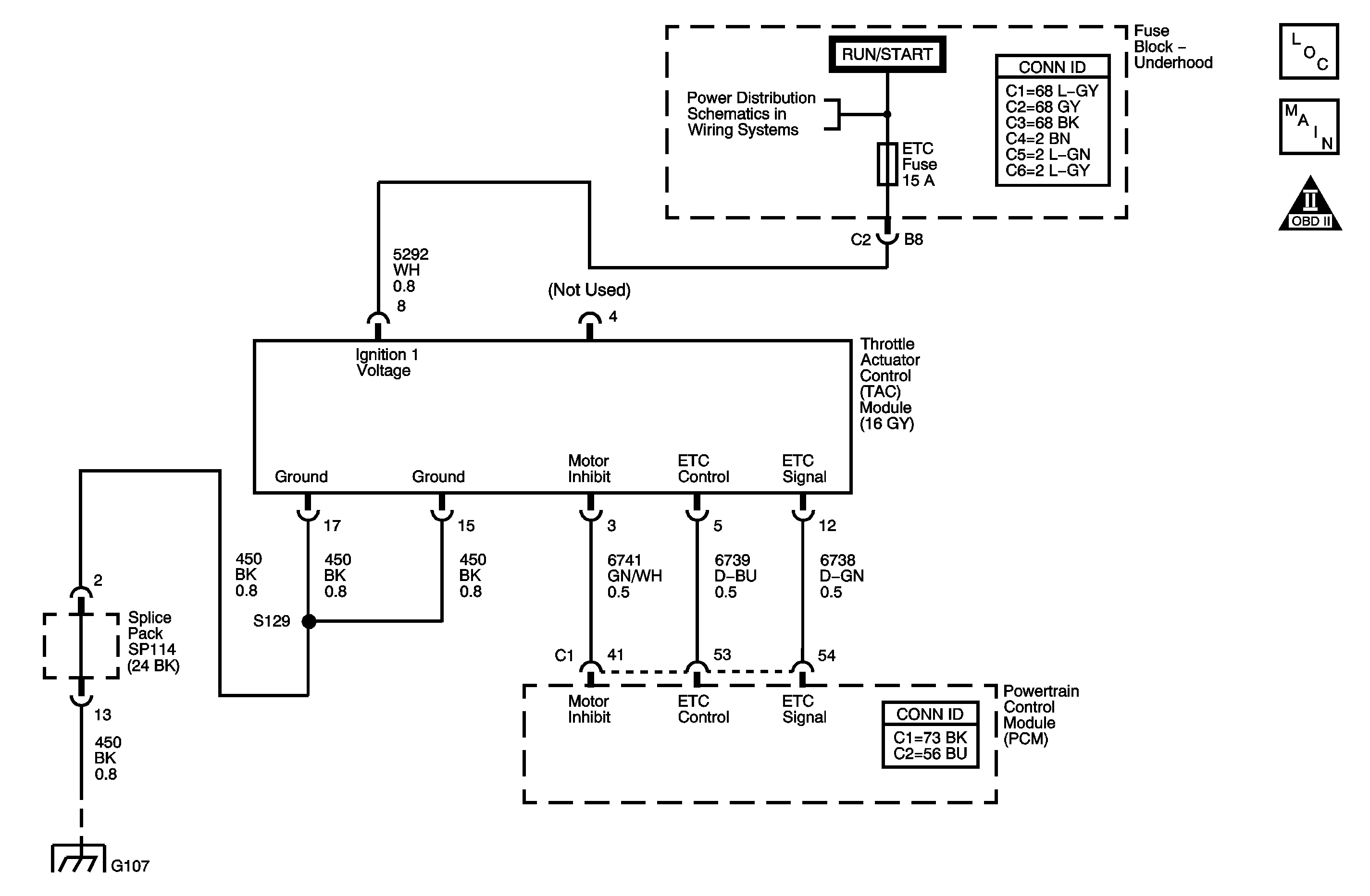
Description
The DTC P2554 Throttle Actuator Control (TAC) Inhibit Circuit Low Voltage diagnostic detects a fault in the TAC motor control circuit. The powertrain control module (PCM) receives accelerator pedal position (APP) sensor information and calculates the desired throttle position. The PCM sends this desired throttle position or target value to the TAC module. The TAC module achieves the desired throttle position by commanding the throttle control motor to position the throttle valve at the target value. The TAC module then compares the TP sensor 1 value to the target value. If necessary, the throttle control motor is moved slightly in order to obtain the exact target value position. If the TAC motor control circuit voltage is too low, DTC P2554 sets. The TAC motor and circuitry are integral parts of the TAC module and are not serviced separately. The TAC module is not serviceable and must be replaced with the throttle body assembly. For additional information on the operation of the TAC system refer to Throttle Actuator Control (TAC) System Description .
DTC Descriptor
This diagnostic procedure supports the following DTC.
DTC P2554 Throttle Actuator Control (TAC) Inhibit Circuit Low Voltage
Conditions for Running the DTC
| • | DTC P0122, P0123, P0222, P0223, P)641, P0651, P2100, P2101, P2108, P2122, P2123, P2127, P2128, P2138, P2176, and U0107 are not set. |
| • | The ignition is ON. |
| • | DTC P2554 runs continuously once the above conditions are met. |
Conditions for Setting the DTC
| • | The control circuit of the TAC motor is less than 0.48 volts when the motor is active. |
| • | The above conditions is present for at least 160 milliseconds. |
Action Taken When the DTC Sets
| • | The PCM illuminates the malfunction indicator lamp (MIL). |
| • | The PCM records the operating conditions at the time the diagnostic fails. This information will be stored in the Freeze Frame buffer. |
Conditions for Clearing the MIL/DTC
| • | The MIL turns OFF after 3 consecutively passing trips without a fault present. |
| • | A history DTC clears after 40 consecutive warm-up cycles without a fault. |
| • | Perform the scan tool Clear DTC Information function. |
Test Description
The numbers below refer to the step numbers in the diagnostic table.
-
The Diagnostic System Check-Engine Controls prompts the technician to complete some basic checks and store the Freeze Frame data on the scan tool if applicable. This creates an electronic copy of the data taken when the fault occurred. The information is then stored in the scan tool for later reference.
-
The normal voltage reading is approximately 0.67 volts. If the conditions for a DTC P2554 are present, the circuit voltage would default to 0.0 volts.
-
This step checks for an open in the TAC module electrical grounds. The TAC module can not operate correctly if there are faulty electrical grounds.
-
After replacing the TAC module, a new minimum throttle position and idle speed must also be established.
Step | Action | Value(s) | Yes | No |
|---|---|---|---|---|
Connector End View Reference: Powertrain Control Module Connector End Views or Engine Controls Connector End Views | ||||
Did you perform the Diagnostic System Check-Engine Controls? | -- | Go to Step 2 | ||
2 |
Is a DTC P2554 set? | -- | Go to Step 4 | Go to Step 3 |
Is the voltage within the specified range? | 0.63--0.70 V | Go to Intermittent Conditions | Go to Step 4 | |
4 |
Did you find and correct the condition? | -- | Go to Step 7 | Go to Step 5 |
5 |
Did you find and correct the condition? | -- | Go to Step 7 | Go to Step 6 |
Did you complete the replacement? | -- | Go to Step 7 | -- | |
7 |
Does the DTC run and pass? | -- | Go to Step 8 | Go to Step 2 |
8 | With a scan tool, observe the stored information, Capture Info. Does the scan tool display any DTCs that you have not diagnosed? | -- | System OK | |
