For 1990-2009 cars only
Special Tools
J 38185 Hose Clamp Pliers
Removal Procedure
- Drain the generator control module cooling system. Refer to Generator Control Module Cooling System Draining and Filling
- Remove the generator control module coolant pump hose - pump to radiator inlet. Refer to Generator Control Module Coolant Pump Hose Replacement - Pump to Radiator Inlet
- Remove the generator control module coolant pump hose. Refer to Generator Control Module Coolant Pump Hose Replacement
- Disconnect the electrical connectors from the drive motor generator control module coolant pumps.
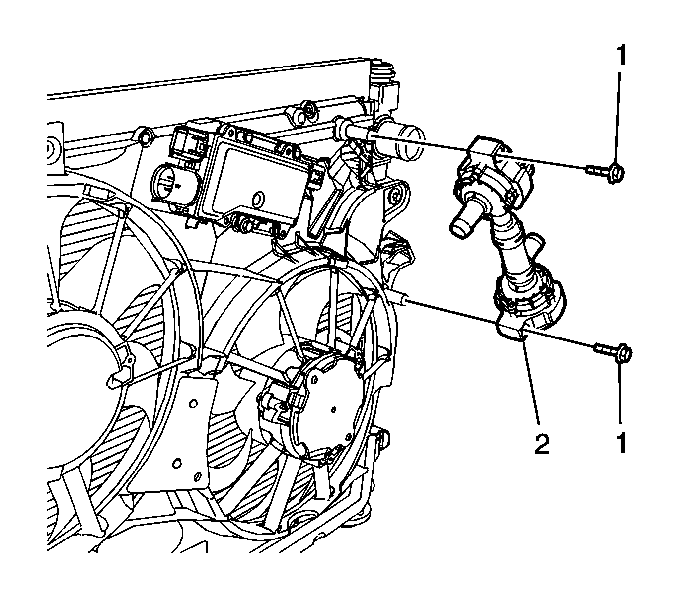
- Remove the drive motor generator control module coolant pump bolts (1).
- Remove the drive motor generator control module coolant pump hose assembly (2) from the vehicle.
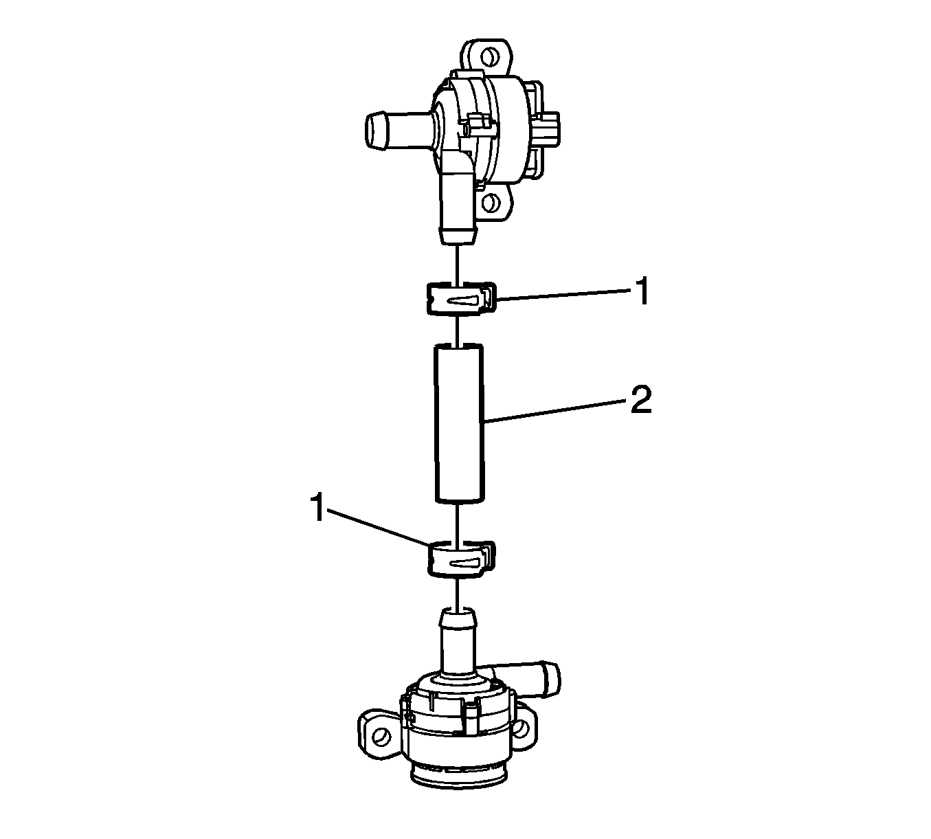
- Remove the drive motor generator control module coolant pump hose clamps (1) using J 38185 Hose Clamp Pliers .
- Remove the drive motor generator control module coolant pump hose (2).


Installation Procedure
- Install the drive motor generator control module coolant pump hose (2).
- Install the drive motor generator control module coolant pump hose clamps (1) using J 38185 Hose Clamp Pliers .
- Install the drive motor generator control module coolant pump hose assembly (2) from the vehicle.
- Install the drive motor generator control module coolant pump bolts (1) and tighten to 7.5 N·m (66 lb in).
- Connect the electrical connectors to the drive motor generator control module coolant pumps.
- Install the generator control module coolant pump hose. Refer to Generator Control Module Coolant Pump Hose Replacement
- Install the generator control module coolant pump hose - pump to radiator inlet. Refer to Generator Control Module Coolant Pump Hose Replacement - Pump to Radiator Inlet
- Fill the generator control module cooling system. Refer to Generator Control Module Cooling System Draining and Filling


Caution: Refer to Fastener Caution in the Preface section.
