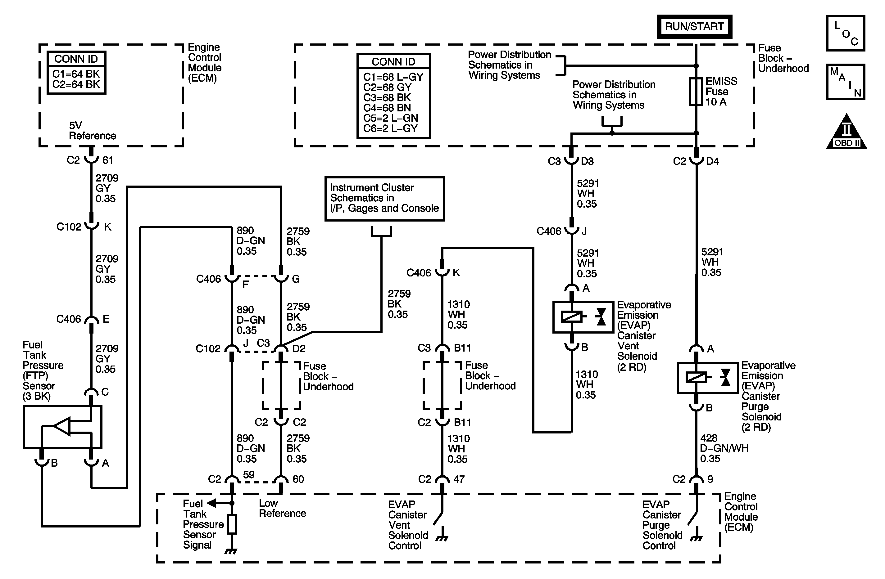
Circuit Description
The fuel tank pressure (FTP) sensor measures the difference between the air pressure or vacuum in the evaporative emission (EVAP) system, and the outside air pressure. The control module supplies a 5-volt reference and a low reference circuit to the FTP sensor. The FTP sensor signal circuit voltage varies depending on EVAP system pressure or vacuum. If the FTP sensor signal voltage goes below a calibrated value, this DTC sets.
The following table illustrates the relationship between the FTP sensor signal voltage and the EVAP system pressure/vacuum.
FTP Sensor Signal Voltage | Fuel Tank Pressure |
|---|---|
High, Approximately 1.5 Volts or More | Negative Pressure/Vacuum |
Low, Approximately 1.5 Volts or Less | Positive Pressure |
Conditions for Running the DTC
The engine is running.
Conditions for Setting the DTC
| • | The FTP voltage is less than 0.1 volt. |
| • | All conditions present for more than 25 seconds. |
Action Taken When the DTC Sets
| • | The control module illuminates the malfunction indicator lamp (MIL) when the diagnostic runs and fails. |
| • | The control module records the operating conditions at the time the diagnostic fails. The control module stores this information in the Freeze Frame/Failure Records. |
Conditions for Clearing the MIL/DTC
| • | The control module turns OFF the malfunction indicator lamp (MIL) after 3 consecutive ignition cycles that the diagnostic runs and does not fail. |
| • | A current DTC, Last Test Failed, clears when the diagnostic runs and passes. |
| • | A history DTC clears after 40 consecutive warm-up cycles, if no failures are reported by this or any other emission related diagnostic. |
| • | Clear the MIL and the DTC with a scan tool. |
Diagnostic Aids
| • | If DTC P0122 and P0530 are also set, a short to ground on the 5-volt reference circuit may exist. |
| • | If DTC P1635 is set, diagnose that DTC first. |
| • | To locate an intermittent problem, use the scan tool to monitor FTP sensor voltage with the ignition ON, the engine OFF. Wiggling wires while watching for a change in FTP sensor voltage may locate the area where an open or short to ground in the wiring could lie. |
| • | The signal voltage with the fuel cap OFF should read between 1.30-1.70 volts, which represents atmospheric pressure, or 0 inches of vacuum. |
Step | Action | Values | Yes | No | ||||
|---|---|---|---|---|---|---|---|---|
Schematic Reference: Engine Controls Schematics Connect End View Reference: Engine Control Module Connector End Views or Engine Controls Connector End Views | ||||||||
1 | Did you perform the Diagnostic System Check-Engine Controls? | -- | Go to Step 2 | |||||
2 | Observe the Fuel Tank Pressure Sensor parameter with a scan tool. Is the Fuel Tank Pressure Sensor parameter less than the specified value? | 0.1 V | Go to Step 4 | Go to Step 3 | ||||
3 |
Did the DTC fail this ignition? | -- | Go to Step 4 | Go to Diagnostic Aids | ||||
4 |
Is the voltage within the specified value? | 4.8-5.2 V | Go to Step 6 | Go to Step 5 | ||||
5 | Disconnect the following components, while monitoring the DMM:
Is the DMM within the specified value when any of the components are disconnected? | 4.8-5.2 V | Go to Step 11 | Go to Step 7 | ||||
6 |
Is Fuel Tank Pressure Sensor parameter within the specified value? | 4.8-5.2 V | Go to Step 9 | Go to Step 8 | ||||
7 | Test the FTP 5-volt reference circuit for an open or for a short to ground. Refer to Circuit Testing and Wiring Repairs in Wiring Systems. Did you find and correct the condition? | -- | Go to Step 14 | Go to Step 10 | ||||
8 | Test the FTP signal circuit for an open or for a short to ground. Refer to Circuit Testing and Wiring Repairs in Wiring Systems. Did you find and correct the condition? | -- | Go to Step 14 | Go to Step 10 | ||||
9 | Test for an intermittent and for a poor connection at the FTP sensor. Refer to Testing for Intermittent Conditions and Poor Connections and Connector Repairs in Wiring Systems. Did you find and correct the condition? | -- | Go to Step 14 | Go to Step 12 | ||||
10 | Test for an intermittent and for a poor connection at the control module. Refer to Testing for Intermittent Conditions and Poor Connections and Connector Repairs in Wiring Systems. Did you find and correct the condition? | -- | Go to Step 14 | Go to Step 13 | ||||
11 | Replace the component that affected the 5-volt reference circuit. Refer to Throttle Body Assembly Replacement or Air Conditioning (A/C) Refrigerant Pressure Sensor Replacement in Heating, Ventilation and Air Conditioning. Did you complete the replacement? | -- | Go to Step 14 | -- | ||||
12 | Replace the FTP sensor. Refer to Fuel Tank Pressure Sensor Replacement . Did you complete the replacement? | -- | Go to Step 14 | -- | ||||
13 | Replace the control module. Refer to Engine Control Module Replacement . Did you complete the replacement? | -- | Go to Step 14 | -- | ||||
14 |
Did the DTC fail this ignition? | -- | Go to Step 2 | Go to Step 15 | ||||
15 | Observe the Capture Info with a scan tool. Are there any DTCs that have not been diagnosed? | -- | System OK | |||||
