For 1990-2009 cars only
Removal Procedure
- Disconnect and remove the battery. Refer to Battery Replacement in Engine Electrical.
- Remove and position aside the underhood electrical center. Refer to Underhood Electrical Center or Junction Block Replacement in Wiring Systems.
- Remove the battery box. Refer to Battery Box Replacement in Engine Electrical.
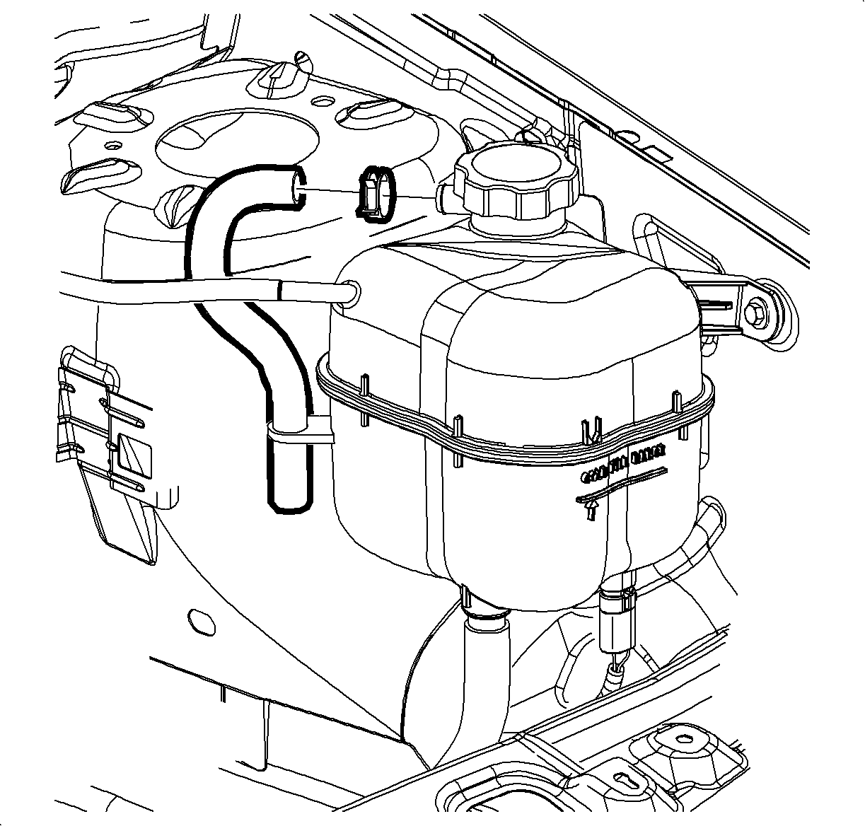
- Disconnect the coolant surge hose from the surge tank and position aside.
- Remove the master cylinder mounting nuts. Do NOT disconnect the brake pipes from the master cylinder.
- Carefully pull the master cylinder away from the vacuum booster and position aside.
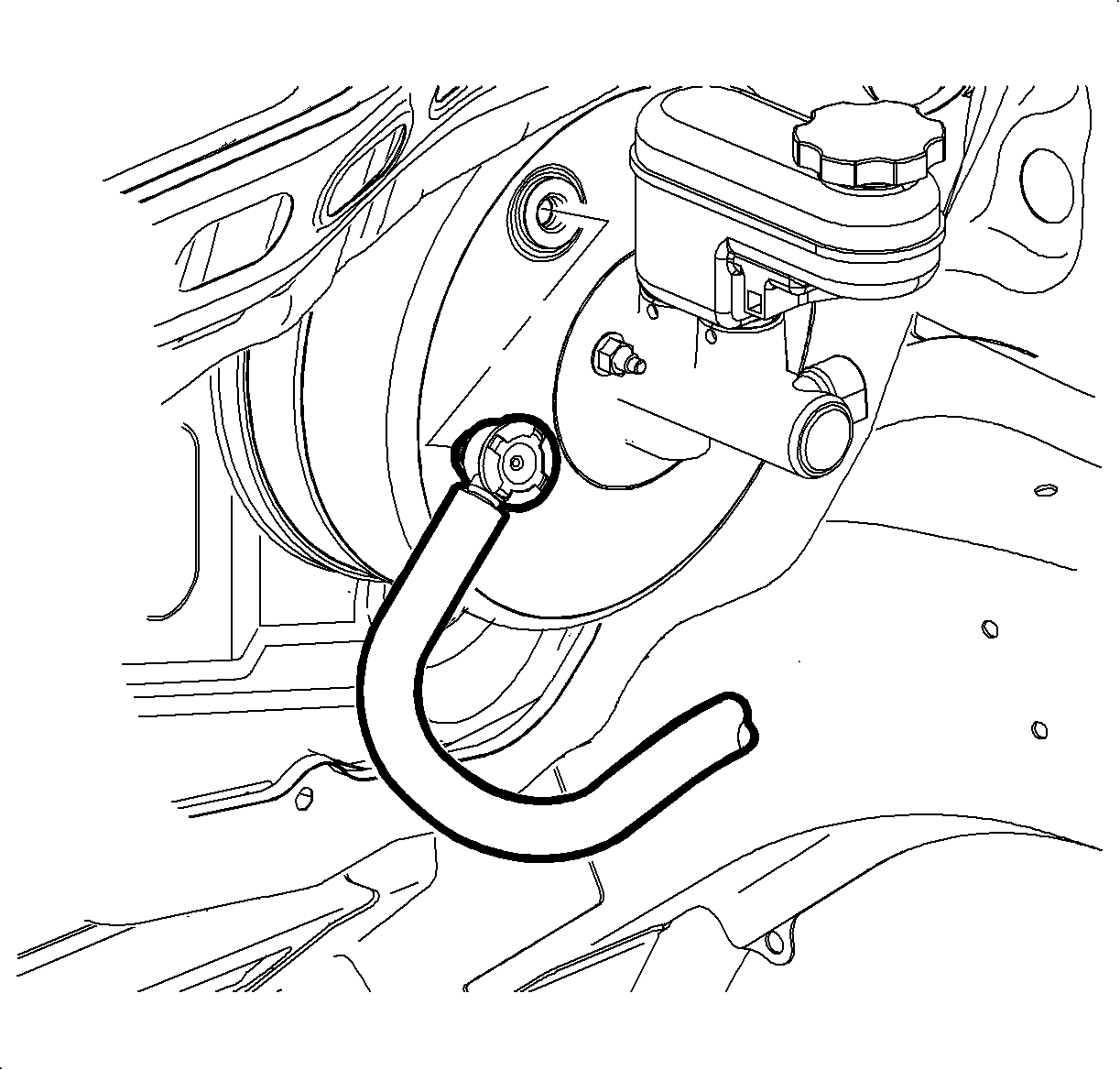
- Disconnect the vacuum booster check valve and hose assembly from the booster. Refer to Vacuum Brake Booster Check Valve and/or Hose Replacement .
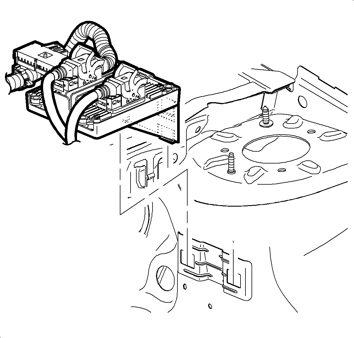
- Remove the transaxle control module (TCM) and position over engine.
- Remove the brake modulator assembly, if equipped. Refer to Brake Pressure Modulator Valve Assembly Replacement in Antilock Brake System.
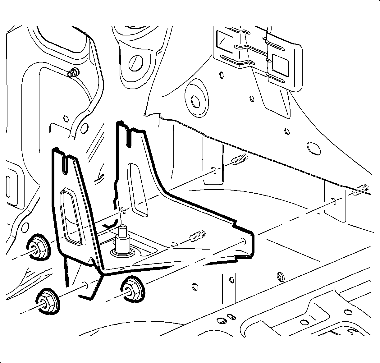
- Remove the brake modulator valve bracket, if equipped. Refer to Brake Pressure Modulator Valve Bracket Replacement in Antilock Brake System.
- Remove the brake booster push rod-to-brake pedal retaining clip.
- Remove the foam washer from the brake pedal assembly.
- Remove the brake booster mounting nuts.
- Disengage the brake booster from the front of dash and the brake pedal bracket. Maneuver the booster toward the center of the vehicle in order to ease removal.
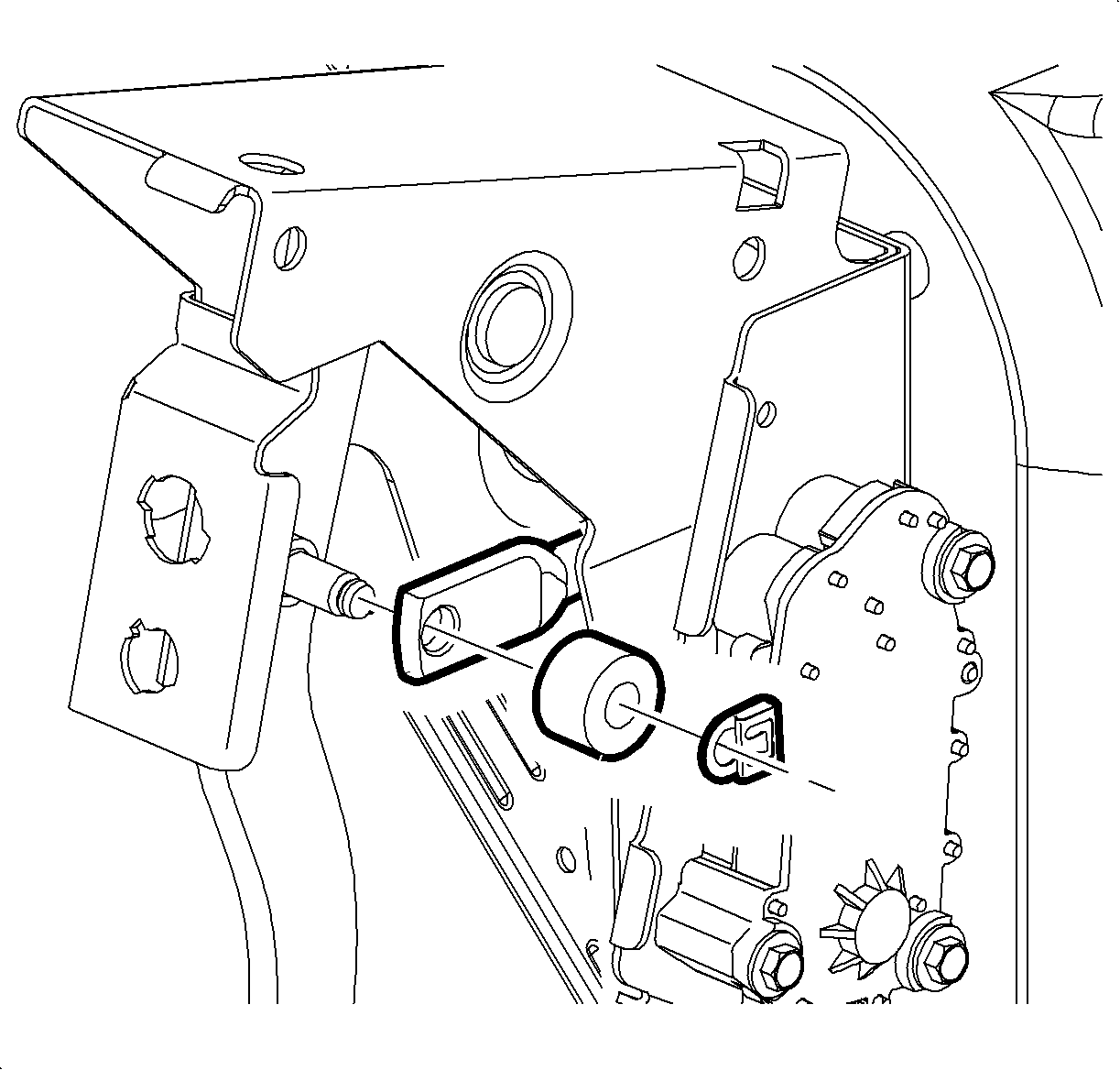
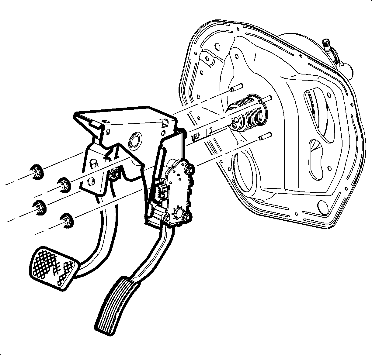
Important: Ensure that the foam insulator on the mounting surface of the brake booster withdraws with the booster.
Installation Procedure
- Install the foam insulator the vacuum brake booster.
- Install the brake booster to the vehicle.
- Install, but do not tighten, the booster mounting nuts.
- Lightly lubricate the booster push rod pivot pin on the brake pedal with silicone lubricant.
- Install the booster push rod to the pivot pin on the brake pedal.
- Install the foam washer to the pivot pin.
- Install the brake booster push rod retaining clip.
- Fully seat the brake booster to the front of dash and the brake pedal assembly.
- Tighten the vacuum brake booster mounting nuts.
- Install the brake modulator valve bracket, if equipped. Refer to Brake Pressure Modulator Valve Bracket Replacement in Antilock Brake System.
- Install the brake modulator assembly, if equipped. Refer to Brake Pressure Modulator Valve Assembly Replacement in Antilock Brake System.
- Install the transaxle control module (TCM) to the bracket.
- Install the vacuum booster check valve and hose assembly to the booster.
- Reposition and install the master cylinder to the booster. Refer to Master Cylinder Replacement .
- Install the coolant surge hose and clamp to the surge tank.
- Install the battery box. Refer to Battery Box Replacement in Engine Electrical.
- Install the underhood electrical center. Refer to Underhood Electrical Center or Junction Block Replacement in Wiring Systems.
- Install and connect the battery. Refer to Battery Replacement in Engine Electrical.
- If necessary, bleed the brake system. Refer to Hydraulic Brake System Bleeding .
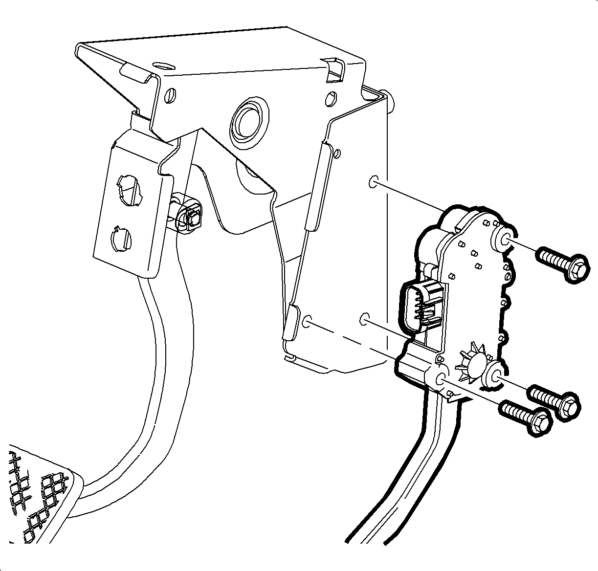

Notice: Refer to Fastener Notice in the Preface section.

Tighten
Tighten the nuts to 25 N·m (18 lb ft).


