Tools Required
| • | J 36346 Fascia Retainer Remover |
| • | J 45404 Transaxle Range Switch Alignment Tool |
Removal Procedure
- Remove the battery. Refer to Battery Replacement .
- Remove the battery box. Refer to Battery Box Replacement .
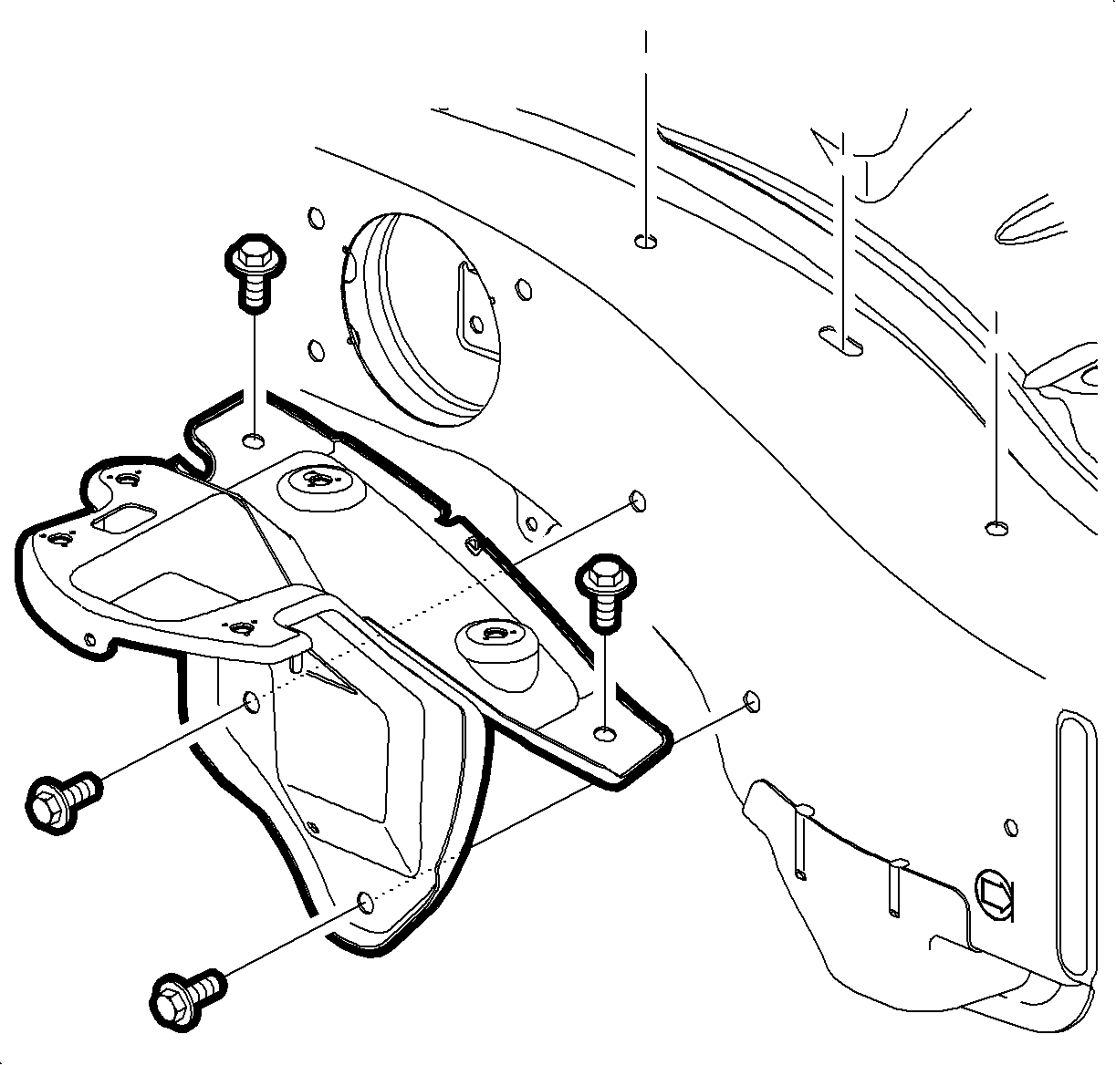
- Loosen the battery tray bracket screws and remove the battery tray bracket.
- Apply the parking brake and place control shift lever in N (Neutral).
- Insert Graphic SMPAT93340AA1. Using Fascia Retainer Remover J 36346 remove the control cable assembly from park/neutral position switch lever.
- Disconnect the electrical harness from park/neutral position.
- Insert Graphic SMPAT95259AA. Remove park/neutral position switch lever and nut.
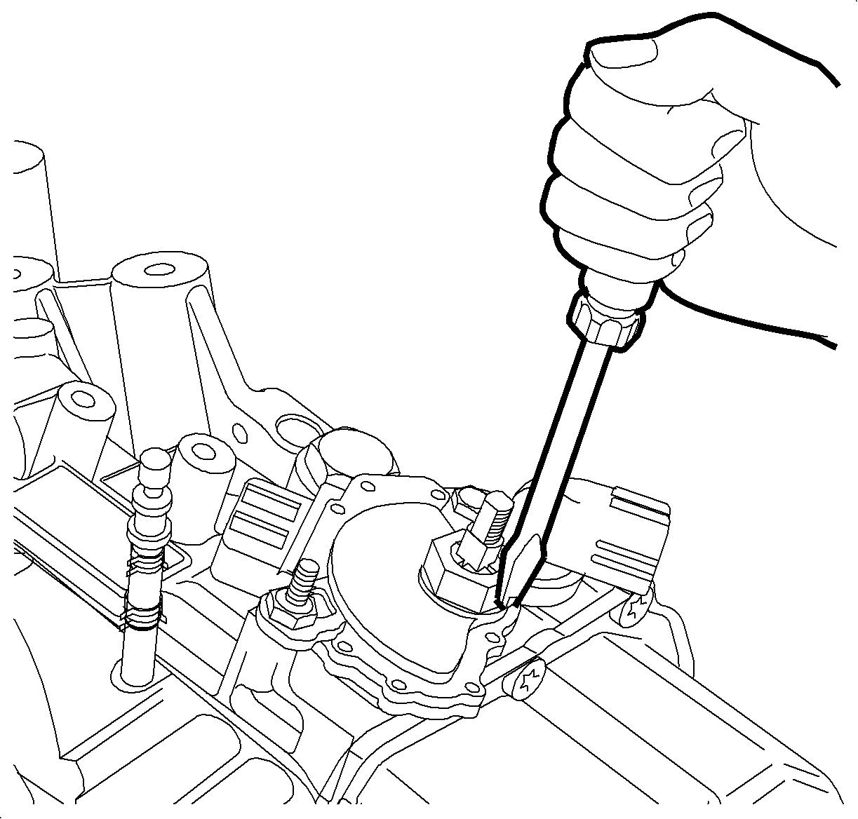
- Using a screwdriver, bend the lockwasher tabs on the manual shaft nut retainer down.
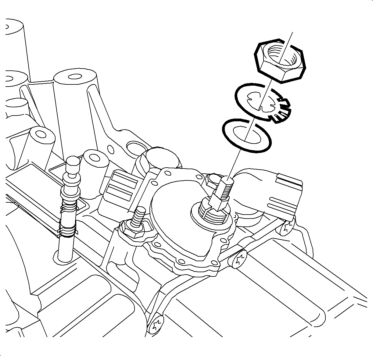
- Remove the nut, lock tab washer and flat washer.
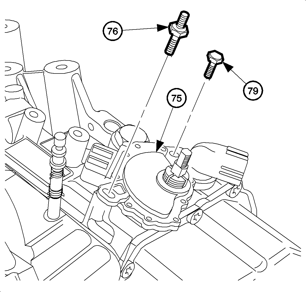
- Remove the park/neutral position switch bolt, stud and flat washers.
- Remove the park/neutral position switch.
Caution: Do not tip the battery over a 45 degree angle or acid could spill causing serious personal injury.
Important: Record all pre-set radio stations.
Important: The transaxle manual shaft must be in N (Neutral) position prior to re-installing the switch.
Installation Procedure
(USING OLD SWITCH)
- Install the park/neutral position switch to the manual valve lever.
- Install the washer stud and the bolt, then hand tighten.
- Install the flat washer, lock tab washer and nut.
- Place the manual valve lever in N (Neutral) position.
- Insert Graphic SMPAT94102AA. Install the Transaxle Range Switch Alignment Tool J 45404 and align the tool pointer to the neutral basic line.
- Remove the alignment tool.
- Tighten the park/neutral position switch bolt and stud.
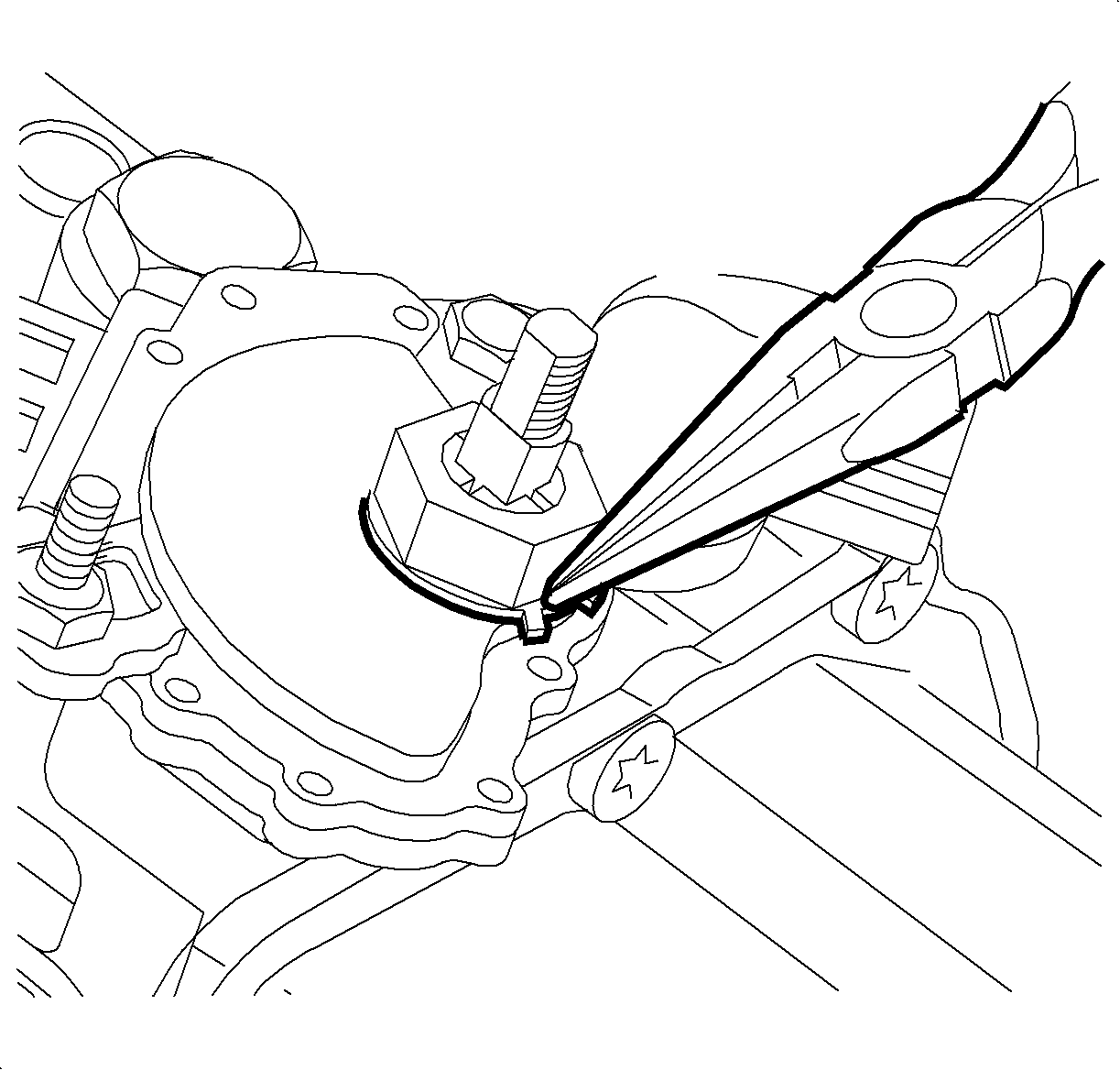
- Move the lock washer into place by bending the tabs up with pliers.
- Connect the electrical harness to the park/neutral position switch.
- Insert Graphic SMPAT95259AA. Install the park/neutral switch lever and nut.
- Install the control cable assembly to the park/neutral switch lever.
- Install the battery tray bracket.
- Position the battery tray bracket and tighten the screws.
- Install the battery box. Refer to Battery Box Replacement .
- Install the battery. Refer to Battery Replacement .
- After adjusting the switch, verify the engine only starts in P (Park) or N (Neutral). If the engine starts in any other position, readjust the switch. Refer to "Park/Neutral Position Switch Adjustment" procedure in this service manual.


Tighten
Tighten the park/neutral position switch nut to
7 N·m (62 lb in).
Tighten
Tighten the park/neutral position switch bolt and
stud to 25 N·m (18 lb ft).
Tighten
Tighten the Park/Neutral position switch lever nut
to 16 N·m (12 lb ft).

Tighten
Tighten the battery tray bracket screws to 16 N·m
(12 lb ft).
Installation Procedure
(USING NEW SWITCH)
- Make sure the transaxle manual shaft is in the N (Neutral) position.
- Install the park/neutral position switch to the manual valve lever.
- Insert Graphic SMPAT94002AA. Tighten the park/neutral position switch bolt and stud.
- Install the flat washer, lock tab washer and nut.
- Move the lock tab washer into place by bending the tabs up with pliers.
- Connect the electrical harness to the park/neutral position switch.
- Insert Graphic SMPAT95259AA. Install the park/neutral position switch lever and nut.
- Insert Graphic SMPAT93340AA1. Install the control cable assembly to the park/neutral position switch lever.
- Install the battery tray bracket.
- Position the battery tray bracket and tighten the screws.
- Install the battery box. Refer to Battery Box Replacement .
- Install the battery. Refer to Battery Replacement .

Tighten
Tighten the park/neutral position switch bolts to
25 N·m (18 lb ft).

Tighten
Tighten the park/neutral position switch nut to
7 N·m (62 lb in).

Tighten
Tighten the park/neutral position switch lever nut
to 16 N·m (12 lb ft).

Tighten
Tighten the battery tray bracket screws to 16 N·m
(12 lb ft).
