For 1990-2009 cars only
Removal Procedure
- Remove the generator control module cover, if equipped. Refer to Generator Control Module Cover Replacement.
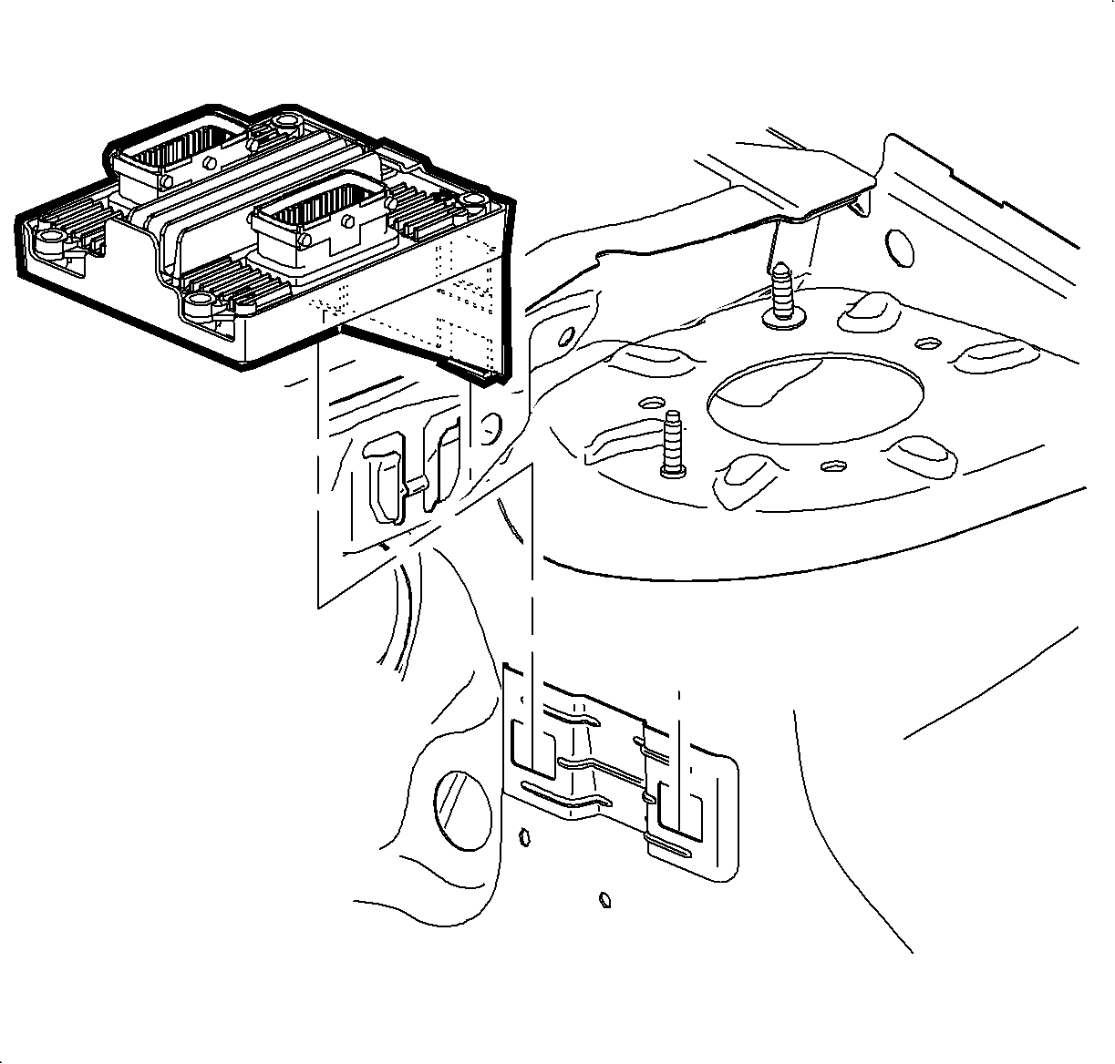
- Remove the transmission control module (TCM), if equipped, from the mounting bracket and position aside.
- Turn the ignition switch to the OFF position.
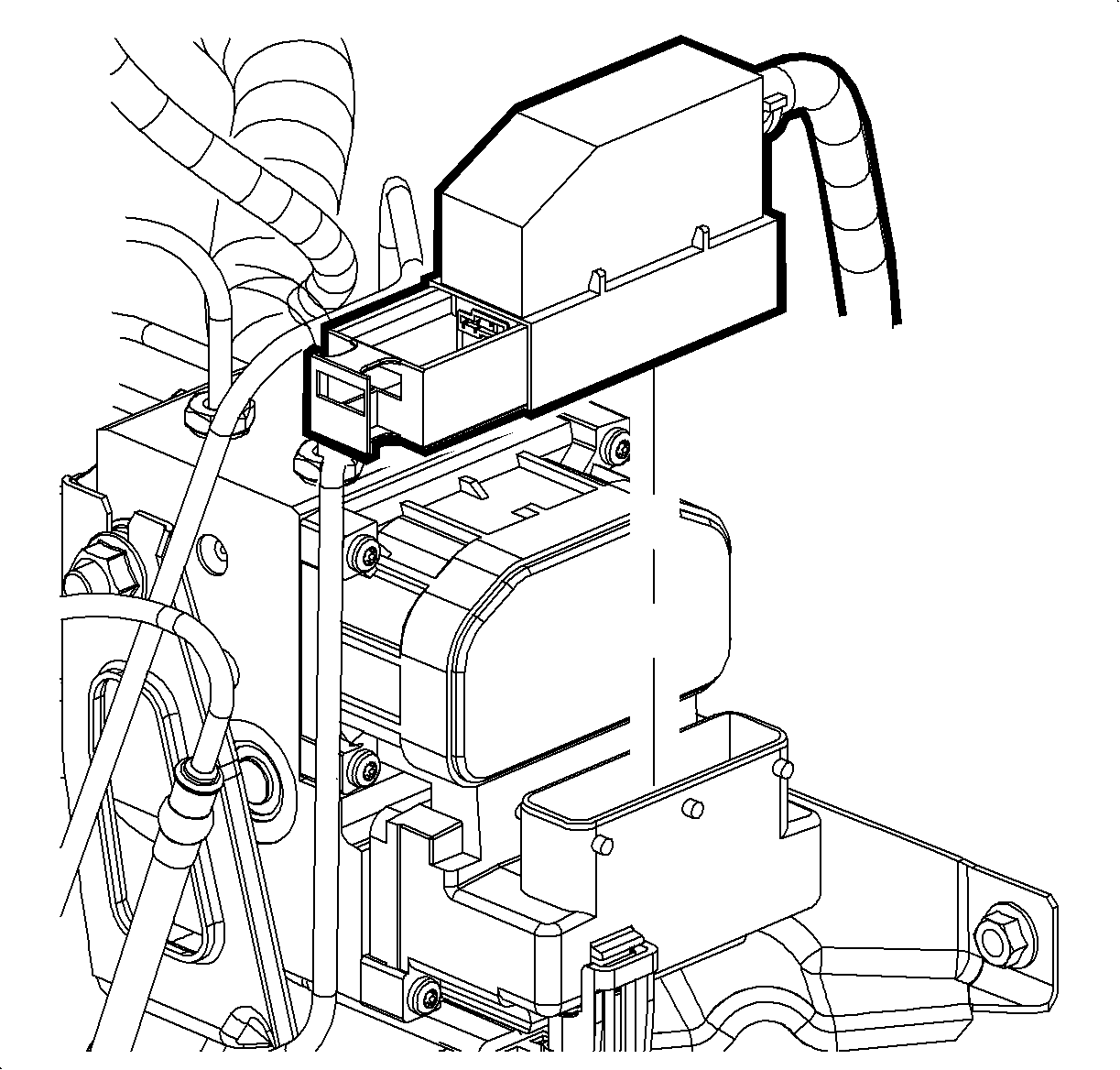
- Disconnect the electronic brake control module (EBCM) electrical connector.
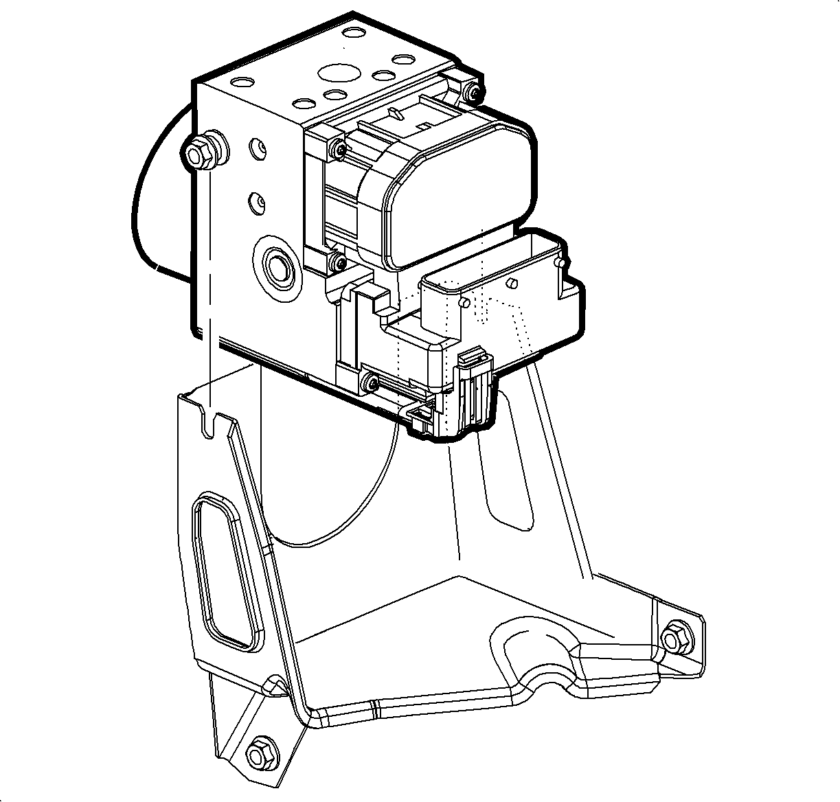
- Loosen the 2 insulator nuts on the brake pressure modulator valve (BPMV) assembly.
- Without disconnecting the brake pipes, remove the bolts from the brake delay valve, if equipped. Refer to Brake Delay Valve Replacement.
- Carefully lift the brake modulator assembly just enough to clear the bracket, then support the assembly.
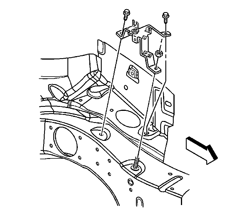
- Remove the brake pressure modulator assembly bracket mounting bolts.
- Remove the bracket from the vehicle.


Installation Procedure
- Install the BPMV assembly bracket to the vehicle.
- Install the brake pressure modulator assembly bracket mounting bolts and nut.
- Install the brake modulator assembly to the bracket.
- Tighten the 2 brake pressure modulator assembly insulator nuts.
- Install the bolts to the brake delay valve, if equipped. Refer to Brake Delay Valve Replacement.
- Connect the EBCM electrical connector.
- Reposition the TCM, if equipped, to the mounting bracket.
- Install the generator control module cover, if equipped. Refer to Generator Control Module Cover Replacement.

Notice: Refer to Fastener Notice in the Preface section.
Tighten
Tighten the bolts and nut to 10 N·m (89 lb in).

Tighten
Tighten the nuts to 10 N·m (89 lb in).


