For 1990-2009 cars only
Special Tools
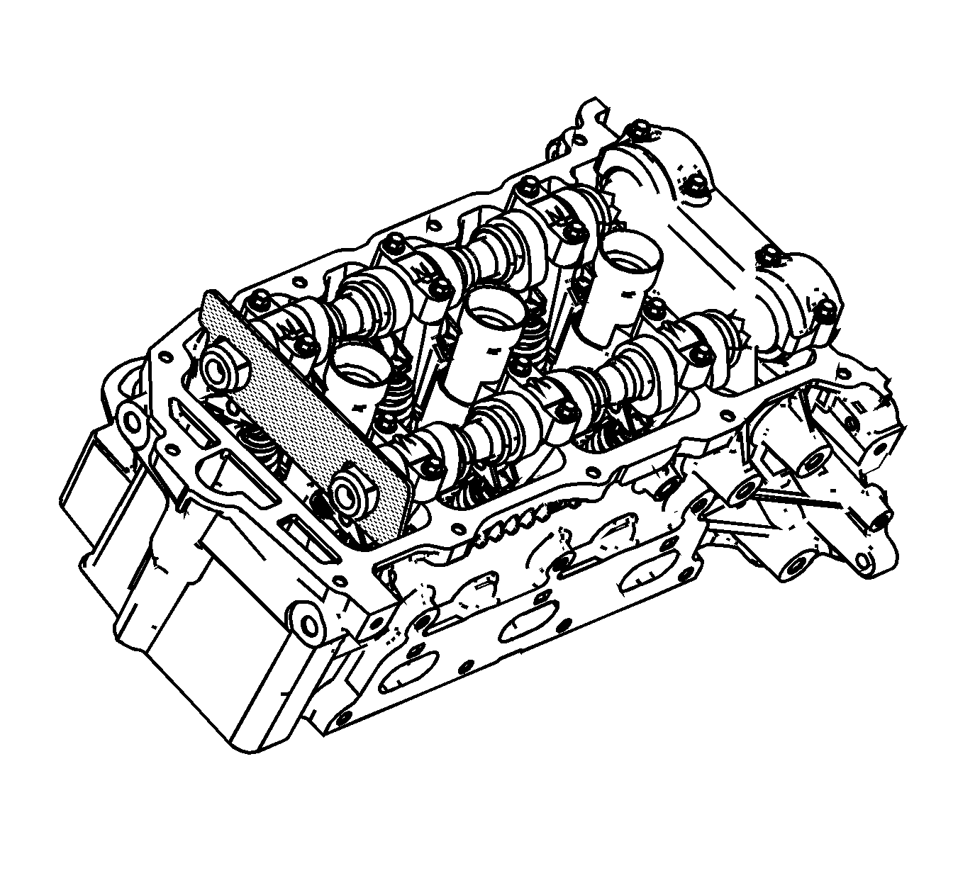
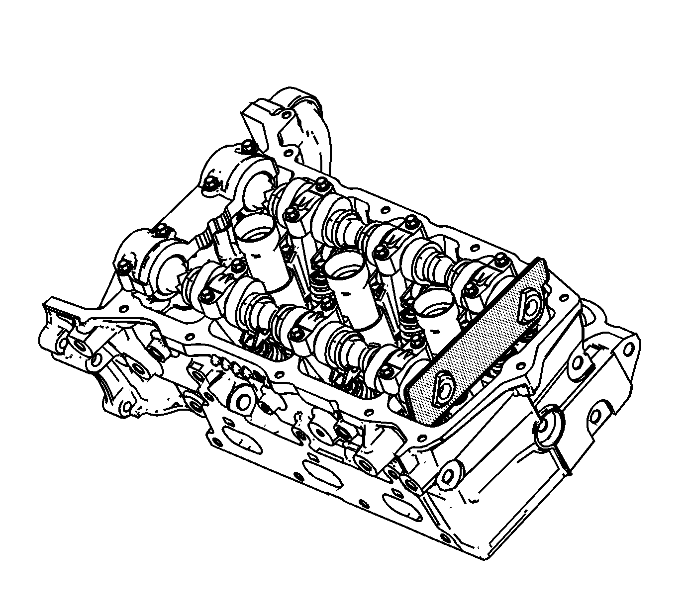
| • | EN 46105 Camshaft Locking Tool |
| • | EN 46109 Guide Pin Set |
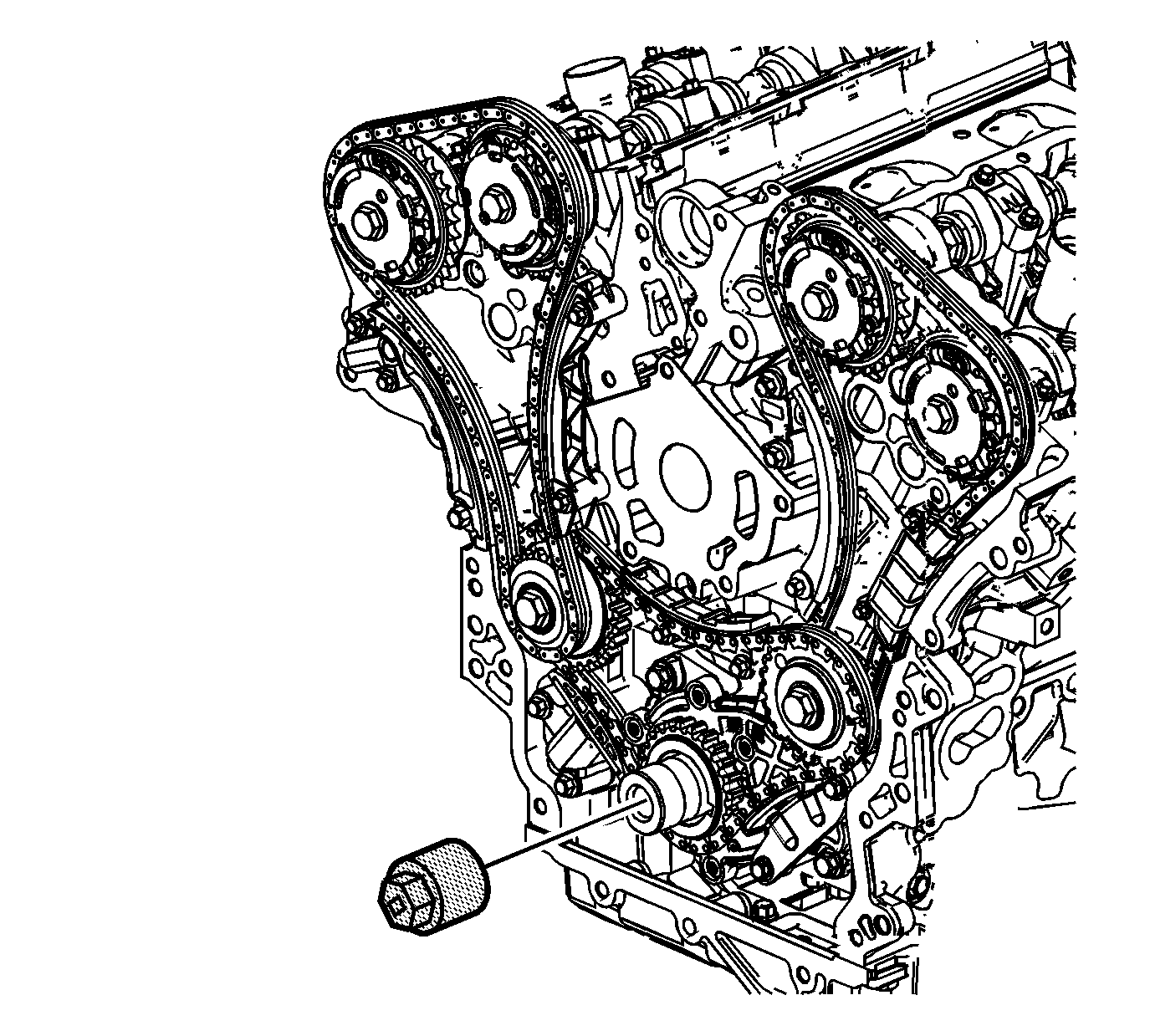
| • | EN 46111 Crankshaft Rotational Socket |
Removal Procedure
- Remove the lower intake manifold. Refer to Lower Intake Manifold Replacement.
- Remove the camshaft covers. Refer to Camshaft Cover Replacement - Left Side and Camshaft Cover Replacement - Right Side.
- Drain the engine coolant. Refer to Cooling System Draining and Filling.
- Remove the water outlet housing assembly. Refer to Water Outlet Housing Replacement.
- Remove the drive belt tensioner. Refer to Drive Belt Tensioner Replacement.
- Remove the water pump. Refer to Water Pump Replacement.
- Remove the power steering pump. Refer to Power Steering Pump Replacement.
- Remove the crankshaft balancer. Refer to Crankshaft Balancer Replacement.
- Remove the camshaft position sensors. Refer to Camshaft Position Sensor Replacement - Bank 2 (Left Side) Exhaust , Camshaft Position Sensor Replacement - Bank 2 (Left Side) Intake , Camshaft Position Sensor Replacement - Bank 1 (Right Side) Exhaust and Camshaft Position Sensor Replacement - Bank 1 (Right Side) Intake.
- Remove the camshaft position actuator solenoid valves from the front cover. Refer to Camshaft Position Actuator Solenoid Valve Solenoid Replacement - Bank 1 (Right Side) Intake , Camshaft Position Actuator Solenoid Valve Solenoid Replacement - Bank 1 (Right Side) Exhaust , Camshaft Position Actuator Solenoid Valve Solenoid Replacement - Bank 2 (Left Side) Intake , and Camshaft Position Actuator Solenoid Valve Solenoid Replacement - Bank 2 (Left Side) Exhaust.
- Remove the generator. Refer to Generator Replacement.
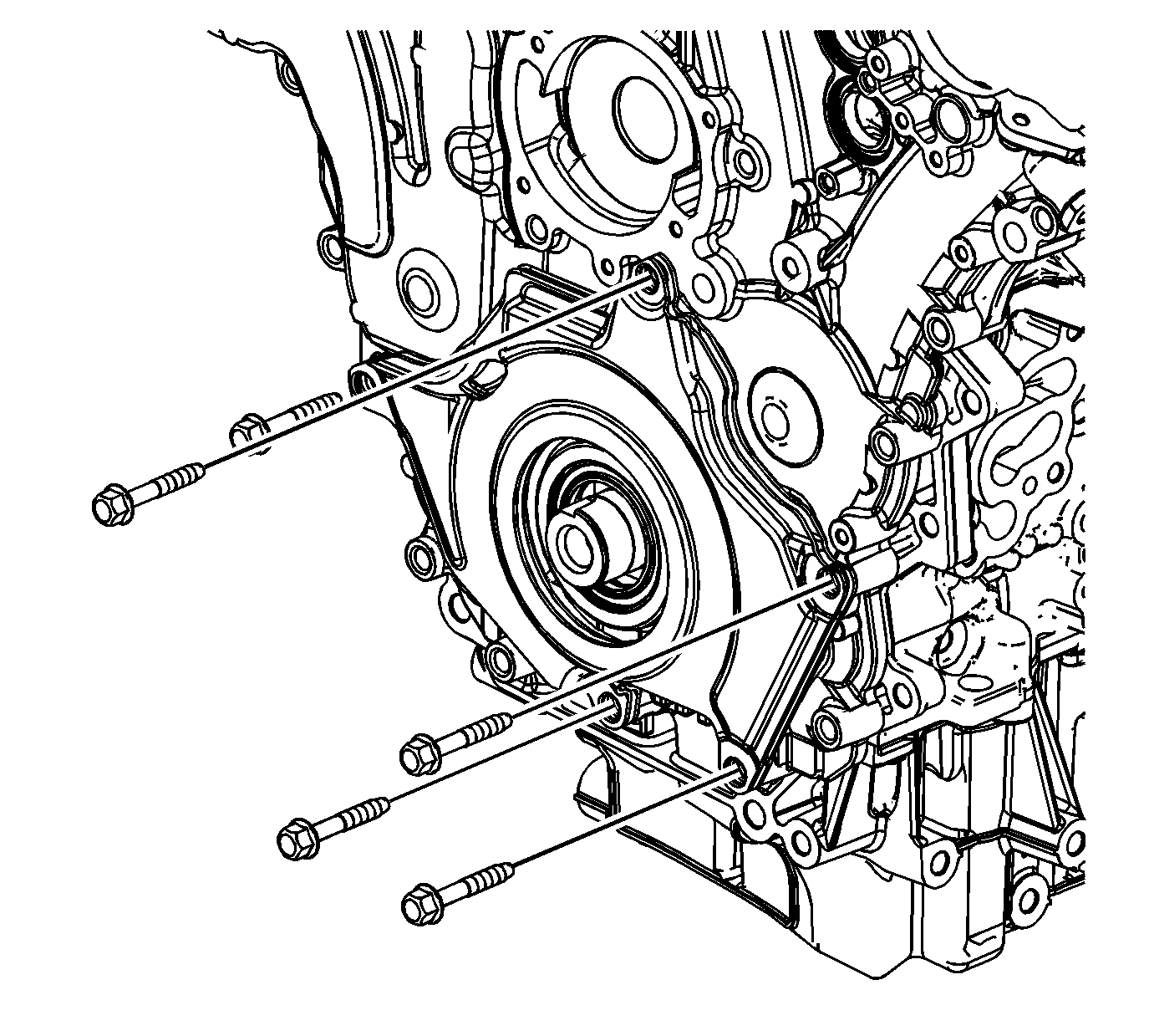
- Remove the engine front cover bolts that hold the engine front cover deadener into position.
- Remove the engine front cover deadener.
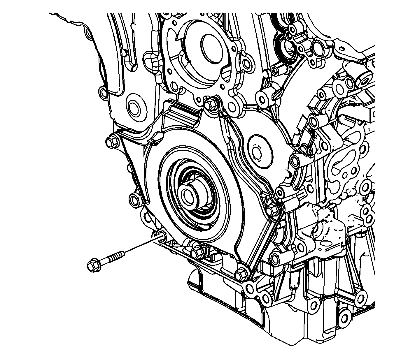
- Remove the remaining engine front cover bolts.
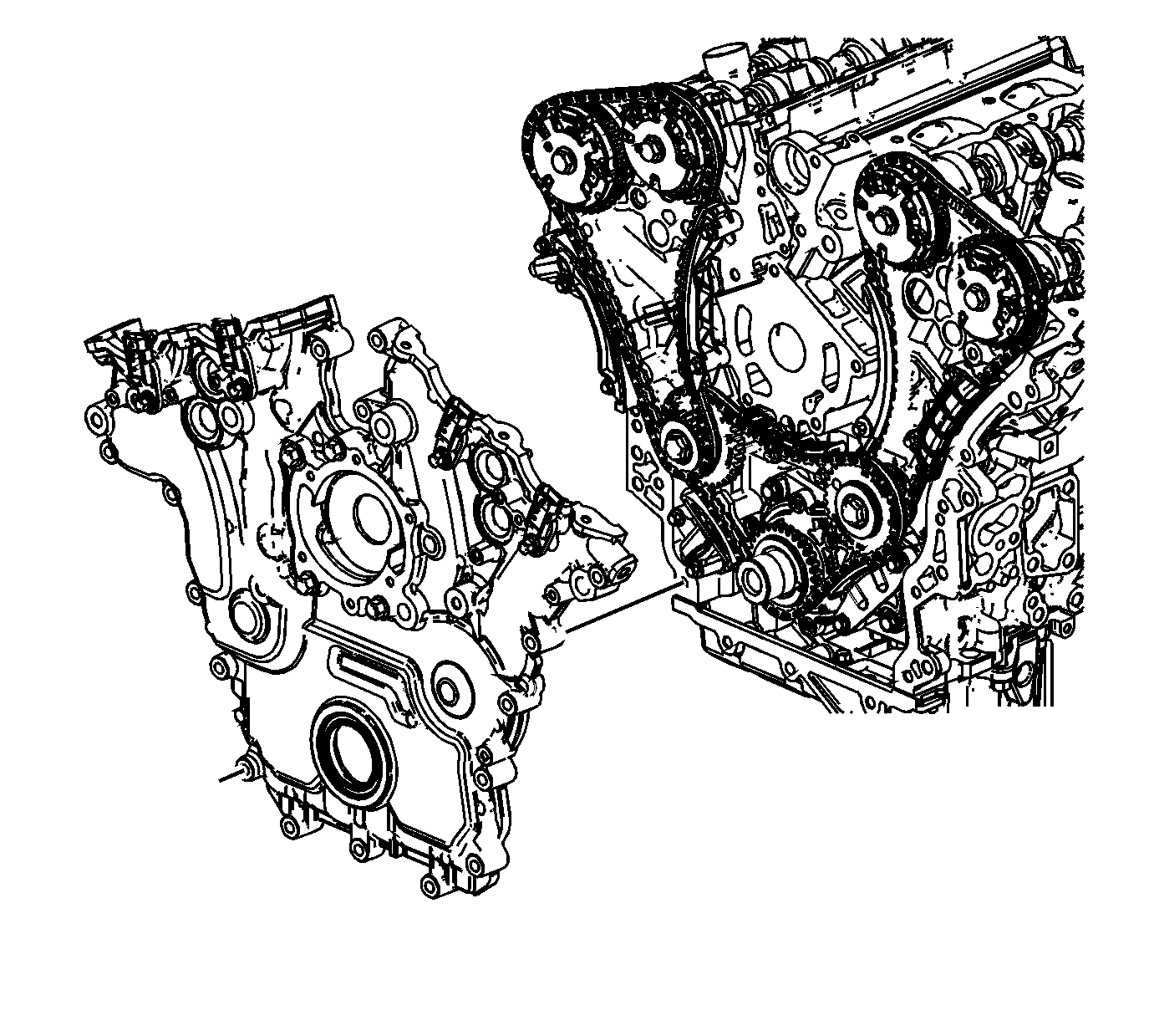
- Loosely install a 10 x 1.5 mm bolt in the "jackscrew" hole (1).
- Using the pry points (2) located at the edge of the front cover and the "jackscrew", separate the RTV sealant.
- Remove the engine front cover.
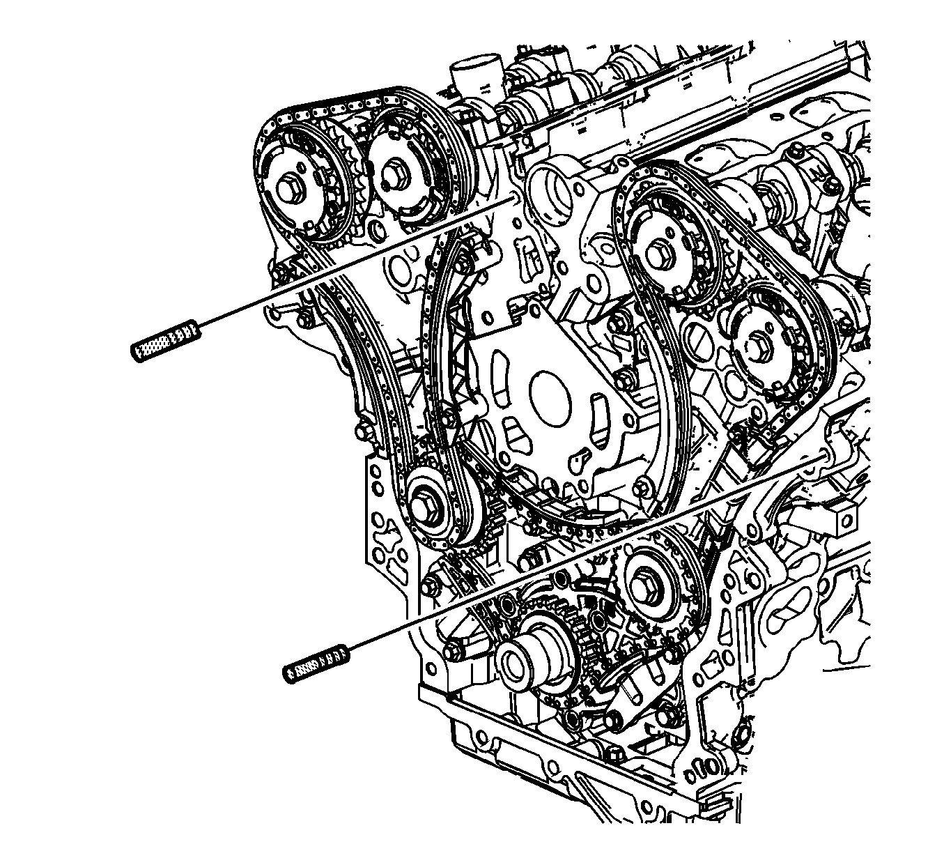
- Using the EN 46111 , rotate the crankshaft until the left cylinder head camshafts align with the EN 46105-2 and the right cylinder head camshafts align with the EN 46105-1.
- Install the EN 46105-1 to the right camshafts.
- Install the EN 46105-2 to the left camshafts.
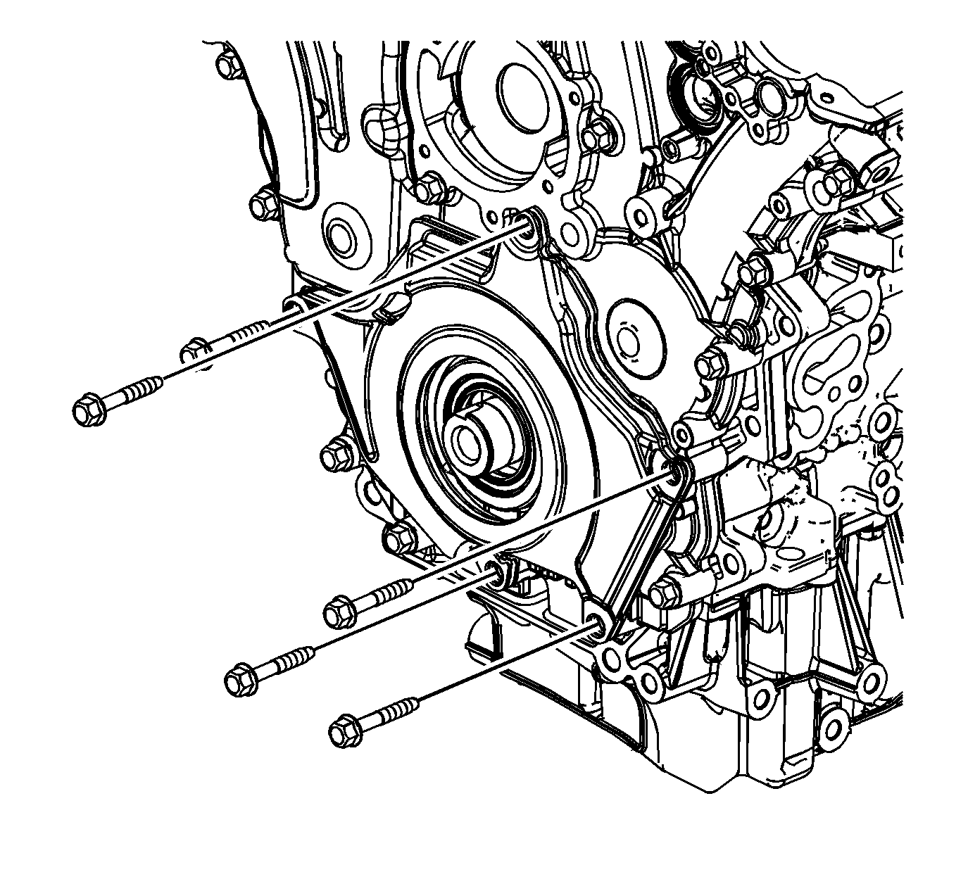
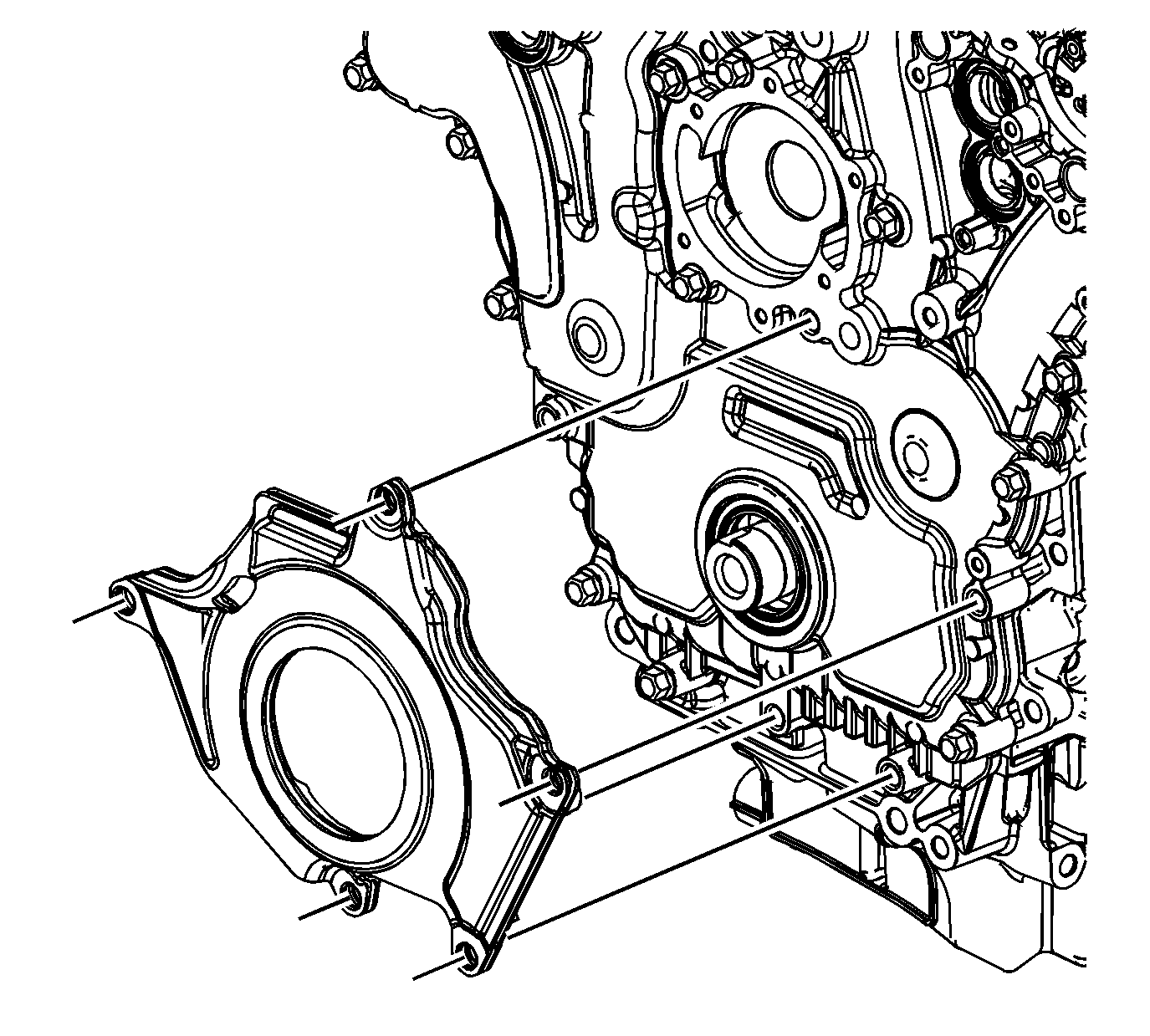
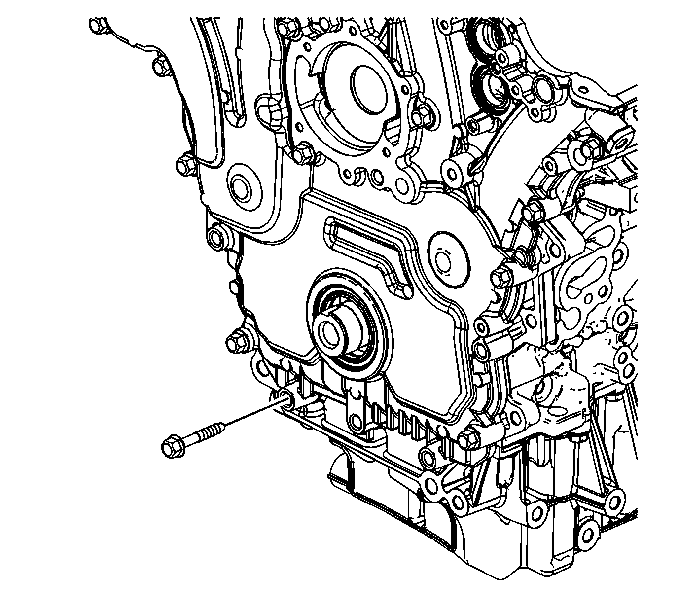
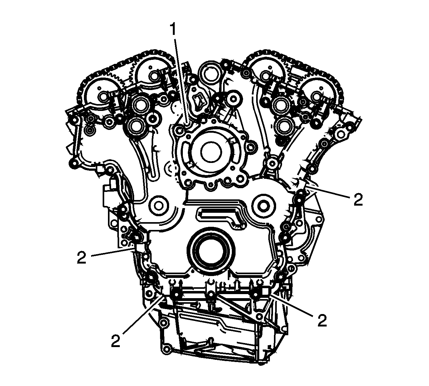
Caution: Do not pry between the engine front cover and the camshaft position sensors or the camshaft position actuators in order to separate the RTV. Use the pry points and a bolt in the jackscrew hole in order to remove the engine front cover. Damage to the camshaft position sensors or the camshaft position actuators may occur if the camshaft position sensors or the camshaft position actuators are used to pry against in order to remove the engine front cover.
Installation Procedure
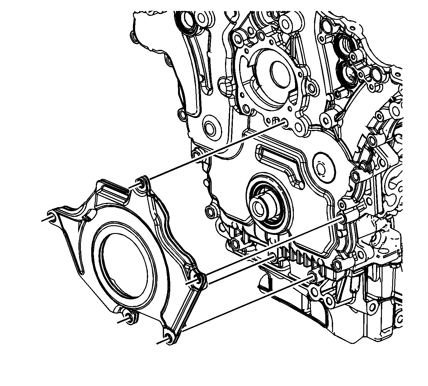
- Install the 8 mm (0.315 in) guide from the EN 46109 into the cylinder block positions as shown.
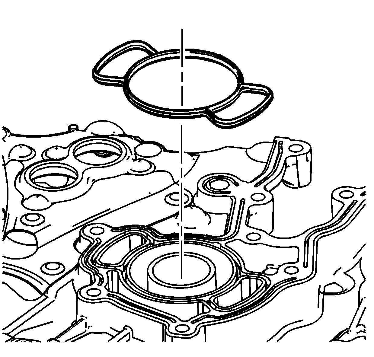
- Install the engine front cover to cylinder block seal.
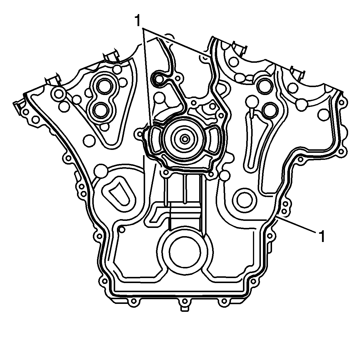
- Place a 3 mm (0.118 in) bead of RTV sealant, GM P/N 12378521 (Canadian P/N 88901148) or equivalent, on the engine.
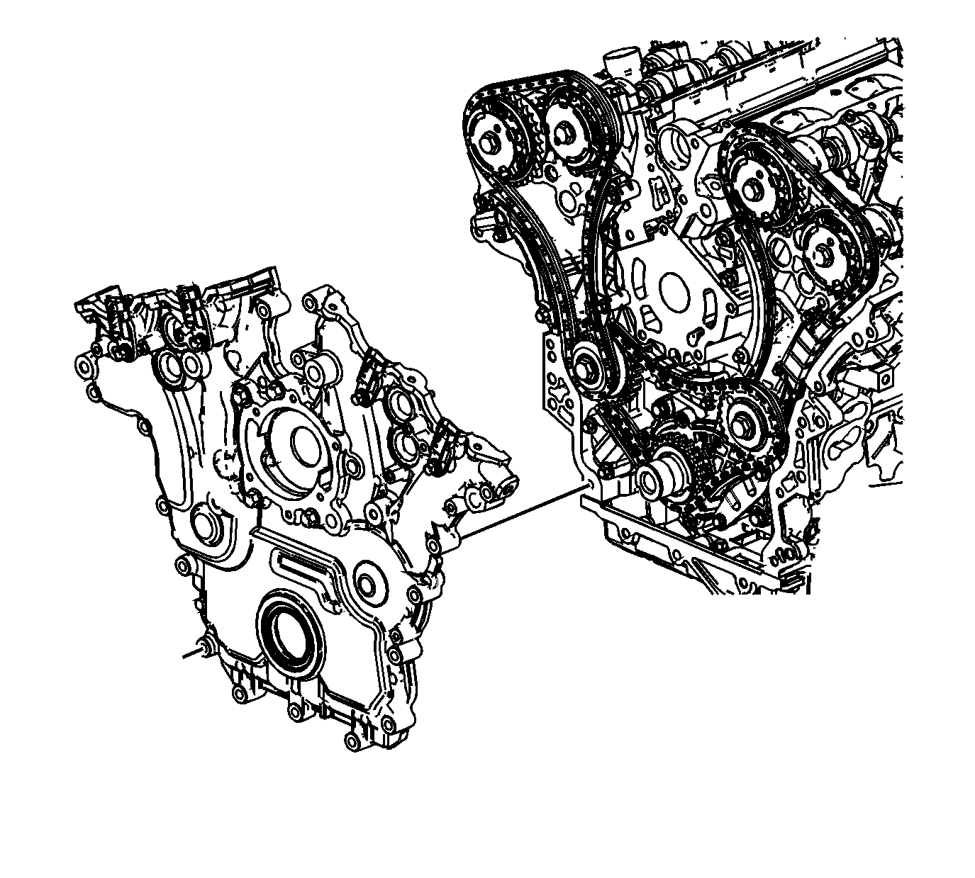
- Place the engine front cover onto the EN 46109 and slide into position.
- Remove the EN 46109 from the cylinder block.
- Install the engine front cover deadener.
- Loosely install the engine front cover bolts to hold the engine front cover deadener into position.
- Loosely install the remaining front cover bolts.
- Tighten the engine front cover bolts in sequence to 20 N·m (14 lb ft).
- Install the generator. Refer to Generator Replacement.
- Install the camshaft position actuator solenoid valves to the front cover. Refer to Camshaft Position Actuator Solenoid Valve Solenoid Replacement - Bank 1 (Right Side) Intake , Camshaft Position Actuator Solenoid Valve Solenoid Replacement - Bank 1 (Right Side) Exhaust , Camshaft Position Actuator Solenoid Valve Solenoid Replacement - Bank 2 (Left Side) Intake , and Camshaft Position Actuator Solenoid Valve Solenoid Replacement - Bank 2 (Left Side) Exhaust.
- Install the camshaft position sensors. Refer to Camshaft Position Sensor Replacement - Bank 2 (Left Side) Exhaust , Camshaft Position Sensor Replacement - Bank 2 (Left Side) Intake , Camshaft Position Sensor Replacement - Bank 1 (Right Side) Exhaust and Camshaft Position Sensor Replacement - Bank 1 (Right Side) Intake.
- Install the crankshaft balancer. Refer to Crankshaft Balancer Replacement.
- Install the power steering pump. Refer to Power Steering Pump Replacement.
- Install the water pump. Refer to Water Pump Replacement.
- Install the water outlet housing assembly. Refer to Water Outlet Housing Replacement.
- Install the drive belt tensioner. Refer to Drive Belt Tensioner Replacement.
- Install the camshaft covers. Refer to Camshaft Cover Replacement - Left Side and Camshaft Cover Replacement - Right Side.
- Install the lower intake manifold. Refer to Lower Intake Manifold Replacement.
- Refill the engine coolant. Refer to Cooling System Draining and Filling.
Caution: Refer to Fastener Caution in the Preface section.
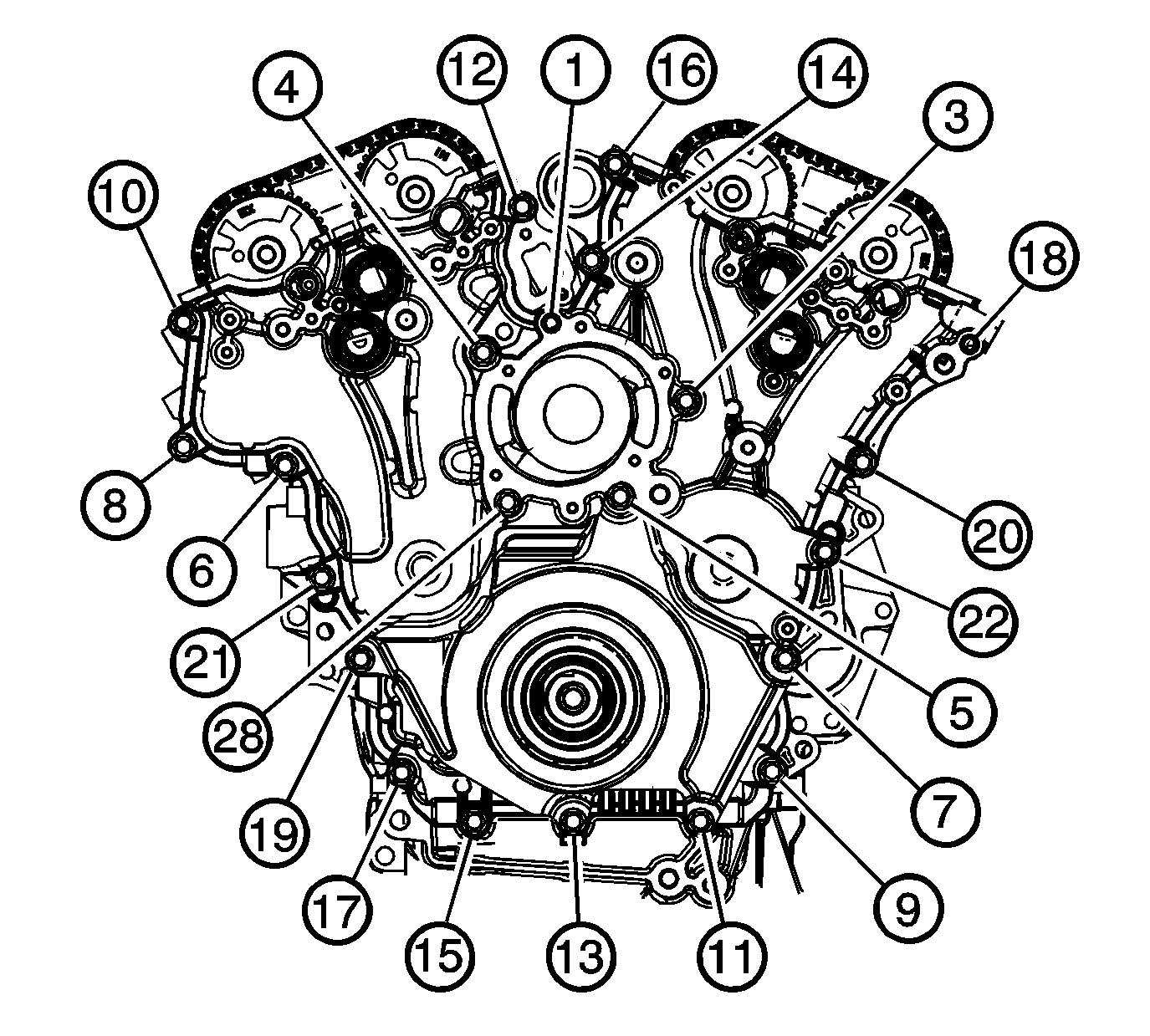
Tighten the engine front cover bolts a second pass in sequence an additional 60 degrees.
