Removal Procedure
- Disconnect the negative battery cable.
- Remove the Valve rocker-arm cover. Refer to Valve Rocker Arm Cover Replacement in Engine Mechanical.
- Remove the timing belt. Refer to Timing Belt Replacement in Engine Mechanical.
- Remove the camshaft. Refer to Camshaft Replacement in Engine Mechanical.
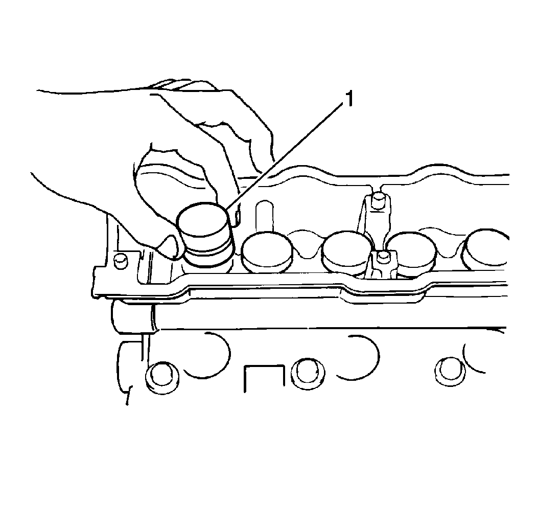
- Remove the six hydraulic valve lash (HVL) adjusters (1) from the cylinder head.
Caution: Unless directed otherwise, the ignition and start switch must be in the OFF or LOCK position, and all electrical loads must be OFF before servicing any electrical component. Disconnect the negative battery cable to prevent an electrical spark should a tool or equipment come in contact with an exposed electrical terminal. Failure to follow these precautions may result in personal injury and/or damage to the vehicle or its components.
Installation Procedure
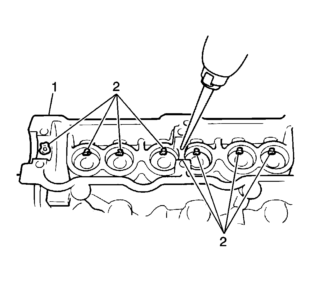
- Pour engine oil through the camshaft journal holes (2).
- Ensure that the engine oil flows out from the oil holes in the HVL adjuster bores.
- Apply engine oil around the HVL adjuster.
- Install the HVL adjuster (1) to the cylinder head.
- Apply engine oil to the camshaft journal and around all of the cams.
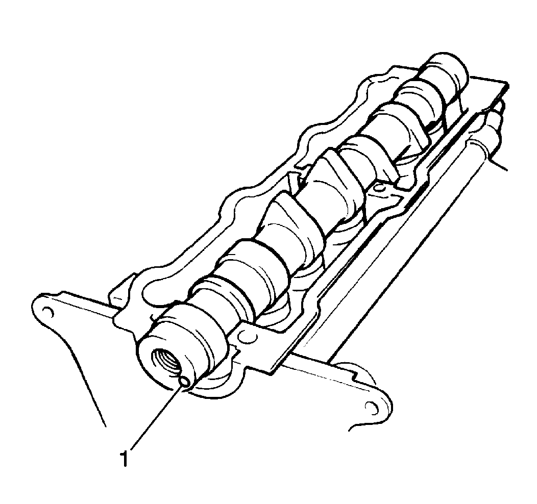
- Install the camshaft into the cylinder head so the pin hole (1) of the camshaft timing gear in the camshaft is at the lower position.
- Apply engine oil to the sliding surface of each housing against the camshaft journal.
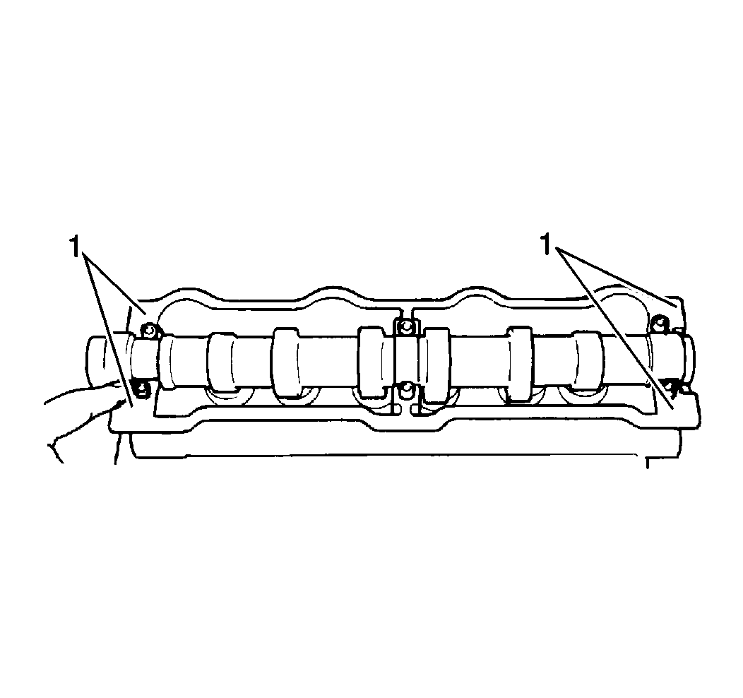
- Apply GM P/N 12346240 or an equivalent to the mating surface of the number 1 and to the number 3 housing (1).These housings will mate with the cylinder head.
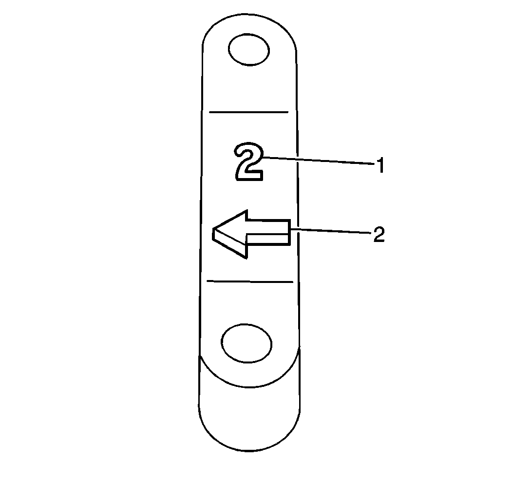
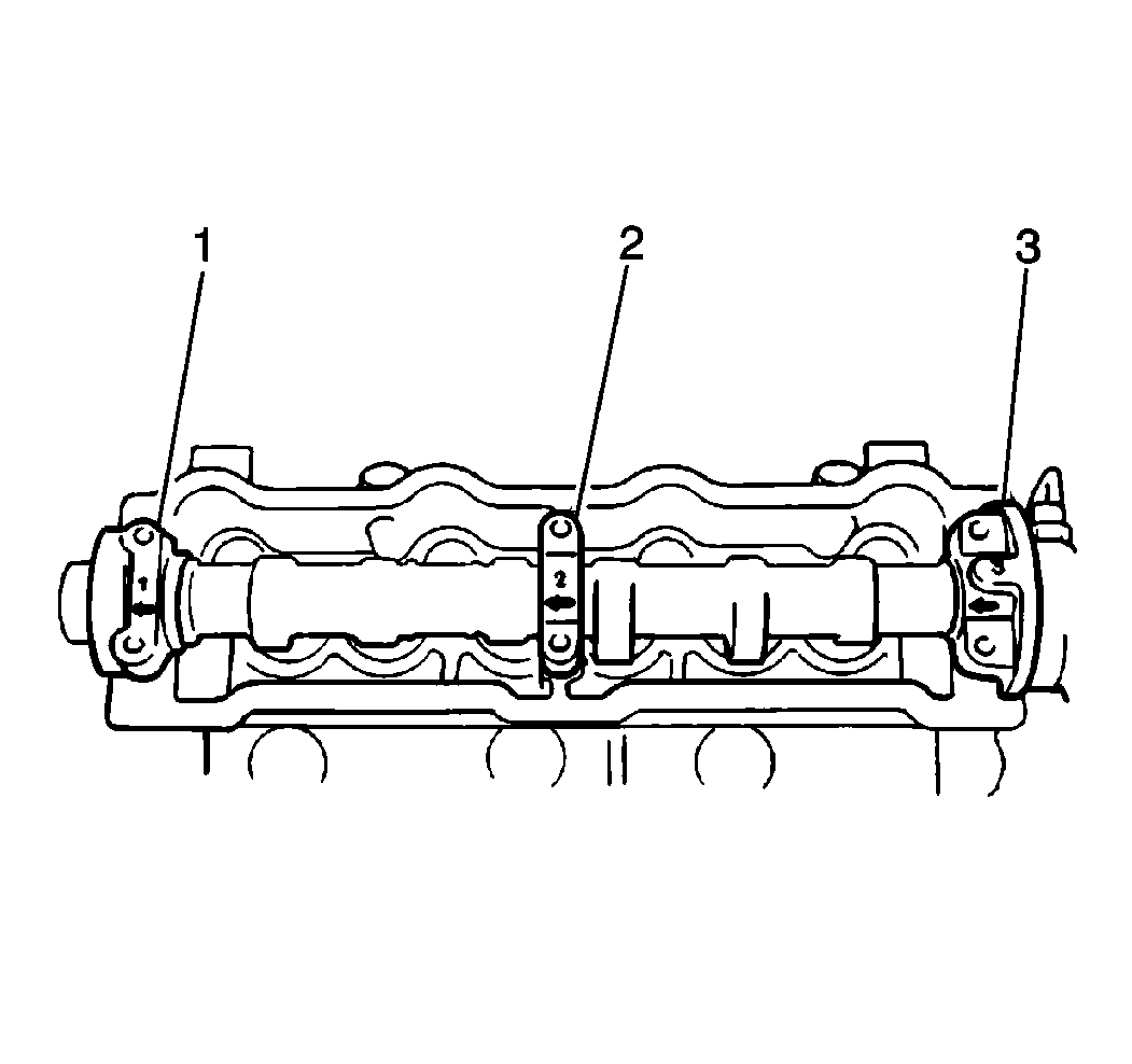
- Install the camshaft housing number 1 (1) to the camshaft and to the cylinder head.Install the camshaft housing so the arrow on the housing (2) faces the timing belt side.
- Install the two remaining camshaft housings (2, 3) to the journals of the camshaft.
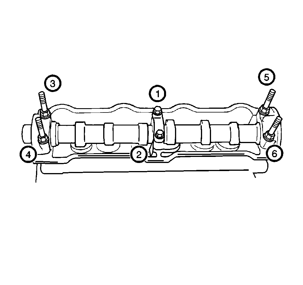
- Secure the camshaft housings with the housing bolts.
- Apply engine oil to the camshaft oil seal lip.
- Press-fit the camshaft oil seal until the oil seal surface becomes flush with the housing surface.
- Install the camshaft. Refer to Camshaft Replacement in Engine Mechanical.
- Install the timing belt. Refer to Timing Belt Replacement in Engine Mechanical.
- Install the valve rocker-arm cover. Refer to Valve Rocker Arm Cover Replacement in Engine Mechanical.

Important: The camshaft housing number 1 retains the camshaft in the proper position as to the thrust direction. First, install the housing number 1 to the journal number 1. Do not tighten completely.
Important: Before you secure the camshaft housings to the camshaft journals, apply a light amount of engine oil to the housing bolts
Notice: Use the correct fastener in the correct location. Replacement fasteners must be the correct part number for that application. Fasteners requiring replacement or fasteners requiring the use of thread locking compound or sealant are identified in the service procedure. Do not use paints, lubricants, or corrosion inhibitors on fasteners or fastener joint surfaces unless specified. These coatings affect fastener torque and joint clamping force and may damage the fastener. Use the correct tightening sequence and specifications when installing fasteners in order to avoid damage to parts and systems.
Tighten
Gradually tighten the housing bolts in sequence.Repeat the tightening
process 3 times or 4 times until the bolts are tightened to 11 N·m
(97 lb in).
