Removal Procedure
- Disconnect the negative battery cable. Refer to Battery Negative Cable Disconnection and Connection in Engine Electrical.
- Disable the SIR system. Refer to Disabling the SIR System in Restraint (SIR) System.
- Remove the windshield side upper garnish moldings. Refer to Windshield Pillar Garnish Molding Replacement in Interior Trim.
- Remove the instrument panel upper trim panel. Refer to Instrument Panel Upper Trim Pad Replacement .
- Remove the front floor console, if equipped. Refer to Front Floor Console Replacement .
- Remove the LH and RH instrument panel insulators. Refer to Instrument Panel Insulator Replacement .
- Remove the steering column opening filler. Refer to Steering Column Opening Filler Replacement .
- Remove the knee bolster from the IP. Refer to Knee Bolster Replacement .
- Remove the steering column. Refer to Steering Column Replacement in Steering Wheel and Column -- Tilt.
- Remove the hood release the handle and position aside. Refer to Hood Primary Latch Release Cable Handle Replacement .
- Remove the data link connector (DLC) bolts and position DLC connector harness aside.
- Remove the front door inside carpet retainers. Refer to Carpet Retainer Replacement in Interior Trim.
- Remove the IP accessory trim plate. Refer to Instrument Panel Accessory Trim Plate Replacement .
- Remove the instrument panel cluster trim plate. Refer to Instrument Cluster Trim Panel Replacement .
- Remove the headlamp switch. Refer to Headlamp Switch Replacement in Lighting Systems.
- Remove the instrument panel cluster. Refer to Instrument Cluster Replacement .
- Remove the radio. Refer to Radio Replacement in Entertainment.
- Remove the HVAC control assembly. Refer to Control Assembly Replacement in HVAC-Manual.
- Remove the instrument panel compartment. Refer to Instrument Panel Compartment Replacement .
- Disconnect the fuse block from the cross vehicle beam by releasing the locking tab and position the fuse block aside.
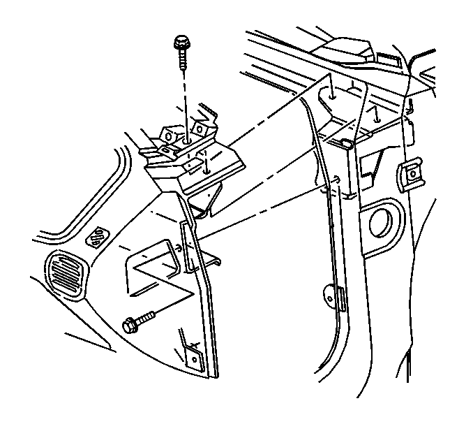
- Remove the bolts from the right side (end) of the instrument panel.
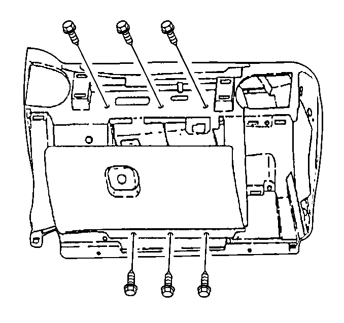
- Remove the center and lower bolts from the instrument panel.
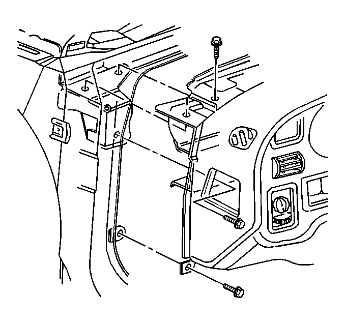
- Remove the bolts from the left side (end) instrument panel.
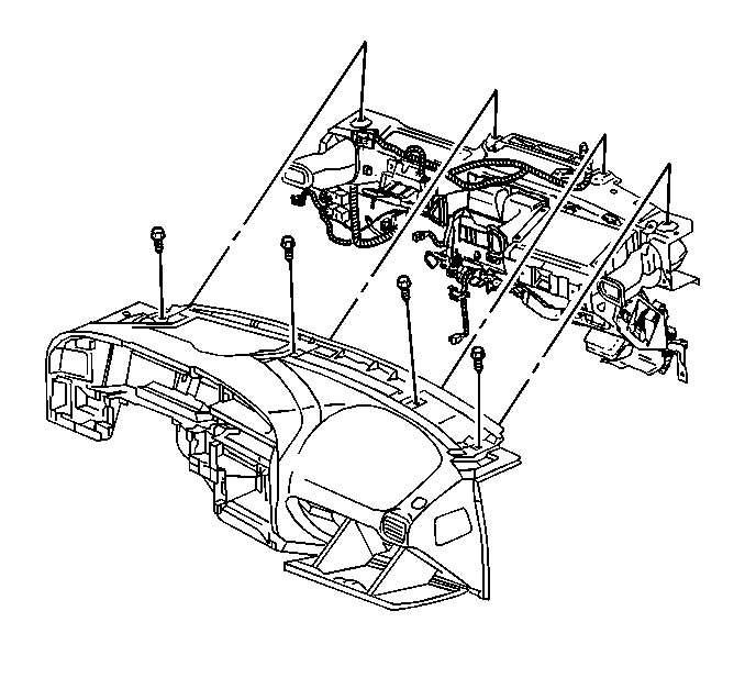
- Remove the bolts from the upper instrument panel.
- Reposition the instrument panel wiring harness away from the instrument panel.
- Remove the instrument panel assembly from the vehicle.


Installation Procedure
- Position the instrument panel assembly to the vehicle.
- Reposition the instrument panel wiring harness to the instrument panel assembly.
- Install the bolts to the upper instrument panel.
- Install the bolts left side (end) of the instrument panel.
- Install the bolts to the center and lower instrument panel.
- Install the bolts to the right side (end) instrument panel.
- Align the fuse block to the cross vehicle beam and install the fuse block securing the locking tab.
- Install the instrument panel compartment. Refer to Instrument Panel Compartment Replacement .
- Install the HVAC control assembly. Refer to Control Assembly Replacement in HVAC-Manual.
- Install the radio. Refer to Radio Replacement in Entertainment.
- Install the instrument panel cluster. Refer to Instrument Cluster Replacement .
- Install the headlamp switch. Refer to Headlamp Switch Replacement in Lighting Systems.
- Install the instrument panel cluster trim plate. Refer to Instrument Cluster Trim Panel Replacement .
- Install the IP accessory trim plate if equipped. Refer to Instrument Panel Accessory Trim Plate Replacement .
- Install the front door inside carpet retainers. Refer to Carpet Retainer Replacement in Interior Trim.
- Position the data link connector (DLC) to the IP and install the bolts .
- Install the hood release handle to the instrument panel. Refer to Hood Primary Latch Release Cable Handle Replacement .
- Install the steering column. Refer to Steering Column Replacement in Steering.
- Install the knee bolster from the IP. Refer to Knee Bolster Replacement .
- Install the LH and RH instrument panel insulators. Refer to Instrument Panel Insulator Replacement .
- Install the front floor console. Refer to Front Floor Console Replacement .
- Install the instrument panel upper trim panel. Refer to Instrument Panel Upper Trim Pad Replacement .
- Install the windshield side upper garnish moldings. Refer to Windshield Pillar Garnish Molding Replacement in Interior Trim.
- Enable the SIR system. Refer to Enabling the SIR System in Restraint (SIR).
- Connect the negative battery cable. Refer to Battery Negative Cable Disconnect/Connect Procedure in Engine Electrical.

Notice: Use the correct fastener in the correct location. Replacement fasteners must be the correct part number for that application. Fasteners requiring replacement or fasteners requiring the use of thread locking compound or sealant are identified in the service procedure. Do not use paints, lubricants, or corrosion inhibitors on fasteners or fastener joint surfaces unless specified. These coatings affect fastener torque and joint clamping force and may damage the fastener. Use the correct tightening sequence and specifications when installing fasteners in order to avoid damage to parts and systems.
Tighten
Tighten the instrument panel upper bolts to 5 N·m (44 lb in).

Tighten
Tighten the instrument panel left side bolts to 20 N·m
(15 lb ft).

Tighten
Tighten the instrument panel center and lower bolts to 5 N·m
(44 lb in).

Tighten
Tighten the instrument panel right side bolts to 20 N·m
(15 lb ft).
Tighten
Tighten the data link connector bolts to 2 N·m (18 lb in).
