Instrument Panel Knee Bolster for Buick LeSabre 1998
Instrument Panel Knee Bolster Buick
Removal Procedure
- Disable the SIR system. Refer to Disabling the SIR System in SIR.
- Remove the right insulator panel. Refer to Instrument Panel Insulator Panel Replacement - Right Side .
- Remove the IP cluster trim panel. Refer to Instrument Cluster Trim Panel Replacement .
- Remove the passenger side inflator module. Refer to Inflatable Restraint Instrument Panel Module Replacement in SIR.
- Remove the IP lower trim pad fasteners.
- Partially remove the IP lower trim pad.
- Disconnect the ashtray electrical connector.
- Disconnect the IP storage compartment light switch electrical connector.
- Disconnect the wiring harness retaining fastener from the .
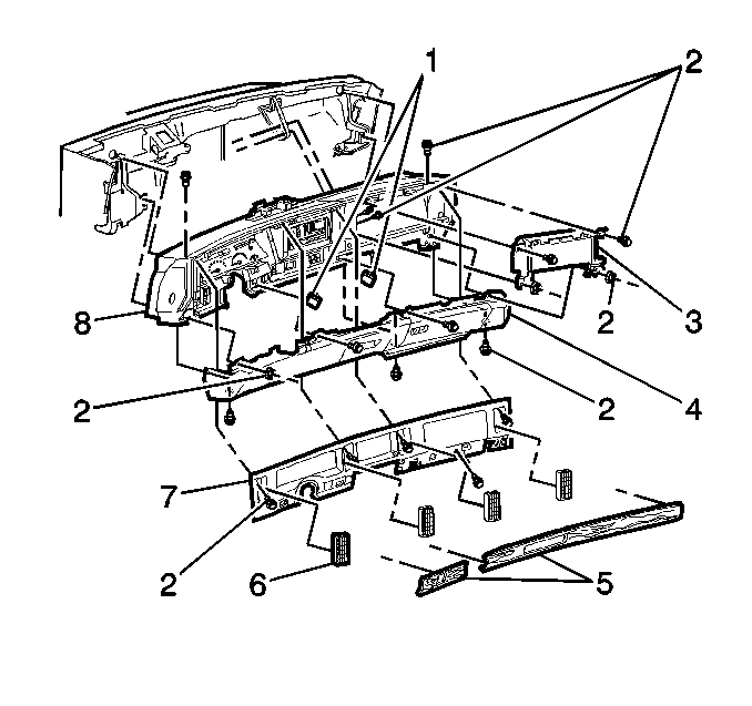
- Remove the IP lower trim pad (4).
Caution: This vehicle is equipped with a Supplemental Inflatable Restraint (SIR) System. Failure to follow the correct procedure could cause the following conditions:
• Air bag deployment • Personal injury • Unnecessary SIR system repairs • Refer to SIR Component Views in order to determine if you are performing service on or near the SIR components or the SIR wiring. • If you are performing service on or near the SIR components or the SIR wiring, disable the SIR system. Refer to Disabling the SIR System.
Installation Procedure
- Partially install the IP lower trim pad (4).
- Connect the wiring harness retaining fastener.
- Connect the IP storage compartment light switch electrical connector.
- Connect the ashtray electrical connector.
- Align the IP lower trim pad.
- Install the fasteners.
- Install the passenger inflator module. Refer to Inflatable Restraint Instrument Panel Module Replacement in SIR.
- Install the IP cluster trim panel. Refer to Instrument Cluster Trim Panel Replacement .
- Install the right insulator panel. Refer to Instrument Panel Insulator Panel Replacement - Right Side .
- Enable the SIR system. Refer to Enabling the SIR System in SIR.
Notice: Use the correct fastener in the correct location. Replacement fasteners must be the correct part number for that application. Fasteners requiring replacement or fasteners requiring the use of thread locking compound or sealant are identified in the service procedure. Do not use paints, lubricants, or corrosion inhibitors on fasteners or fastener joint surfaces unless specified. These coatings affect fastener torque and joint clamping force and may damage the fastener. Use the correct tightening sequence and specifications when installing fasteners in order to avoid damage to parts and systems.
Tighten
Tighten the fasteners to 10 N·m (89 lb in).
Instrument Panel Knee Bolster Oldsmobile
Removal Procedure
After a non-deployment accident, visually inspect the knee bolster for damage or deformation. Any visible damage may indicate structural damage to the IP assembly.
- Remove the IP trim plate. Refer to Instrument Panel Lower Center Trim Replacement .
- Remove the left insulator panel. Refer to Instrument Panel Insulator Panel Replacement - Left Side .
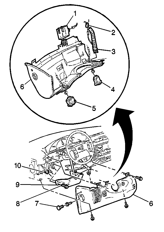
- Remove the plastic cap (7) in the knee bolster panel near the door in order to access the fastener.
- Remove the knee bolster fasteners from the IP.
- Pull the knee bolster (6) rearward.
- Disconnect the air temperature sensor (3).
- Remove the interior lighting control module (1). Refer to Interior Lamp Control Module Replacement in Lighting Systems.
- Disconnect the traction control switch (4) connector.
- Disconnect the rear compartment release switch or rear compartment release/fog lamp switch (5) connector.
- Remove the knee bolster.
- Remove the switches from the knee bolster, as needed. Refer to Rear Compartment Switch Replacement and Electronic Traction Control Switch Replacement .
Installation Procedure
- Install the switches to the knee bolster, as needed. Refer to Rear Compartment Switch Replacement and Electronic Traction Control Switch Replacement .
- Partially install the knee bolster.
- Connect the switch connectors to the switches on the knee bolster.
- Install the interior lighting control module (1). Refer to Interior Lamp Control Module Replacement in Lighting Systems.
- Install the air temperature sensor (3).
- Install the knee bolster (6).
- Install the top knee bolster fasteners.
- Install the bottom fasteners to the knee bolster.
- Install the fastener to the side of the knee bolster.
- Install the plastic cap (7).
- Install the insulator panel. Refer to Instrument Panel Insulator Panel Replacement - Left Side .
- Install the IP trim plate. Refer to Instrument Panel Lower Center Trim Replacement .
Notice: Use the correct fastener in the correct location. Replacement fasteners must be the correct part number for that application. Fasteners requiring replacement or fasteners requiring the use of thread locking compound or sealant are identified in the service procedure. Do not use paints, lubricants, or corrosion inhibitors on fasteners or fastener joint surfaces unless specified. These coatings affect fastener torque and joint clamping force and may damage the fastener. Use the correct tightening sequence and specifications when installing fasteners in order to avoid damage to parts and systems.
Tighten
Tighten the top fasteners to 1.9 N·m (17 lb in).
Tighten
Tighten the bottom fasteners to 10 N·m (88 lb in).
Tighten
Tighten the side fastener to 1.9 N·m (17 lb in).
Instrument Panel Knee Bolster Pontiac
The knee bolster consists of the following components:
| • | The tie bar |
| • | The steering column filler |
The knee bolster is located in the base of the instrument panel (IP) trim panel. The knee bolster extends across the entire IP assembly. The knee bolster is mounted directly to the IP trim panel. The IP trim panel crosses over the top of the steering column and mounts to the steering column upper support. The steering column filler is the only component of the knee bolster that you may replace. The tie bar is an integral part of the IP assembly.
After a non-deployment accident, visually inspect the knee bolster for damage or deformation. Any visible damage indicates other structural damage. The knee bolster cannot be repaired or replaced separate from the IP assembly, the IP assembly must be replaced.
When replacing the knee bolster, note the GM part number. Compare the part numbers at installation in order to ensure that you are installing the correct knee bolster. Refer to Instrument Panel Assembly Removal .
