For 1990-2009 cars only
Camshaft Replacement 6.2L and 7.0L
Special Tools
| • | EN-47812 Installer Bolt |
| • | EN-47813 Front Cover Alignment |
Removal Procedure
- Remove the engine assembly. Refer to Engine Replacement.
- Remove the crankshaft balancer. Refer to Crankshaft Balancer Replacement.
- Remove the left and right exhaust manifolds Refer to Exhaust Manifold Removal - Left Side and Exhaust Manifold Removal - Right Side.
- Remove the water pump. Refer to Water Pump Removal.
- Remove the supercharger. Refer to Supercharger Removal.
- Remove the left and right valve rocker arm covers. Refer to Valve Rocker Arm Cover Removal - Left Side and Valve Rocker Arm Cover Removal - Right Side.
- Remove the valve rocker arms and push rods. Refer to Valve Rocker Arm and Push Rod Removal.
- Remove the left and right cylinder heads. Refer to Cylinder Head Removal - Left Side and Cylinder Head Removal - Right Side.
- Remove the valve lifters. Refer to Valve Lifter Removal.
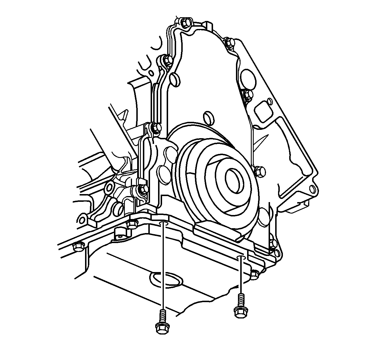
- Remove the oil pan-to-front cover bolts.
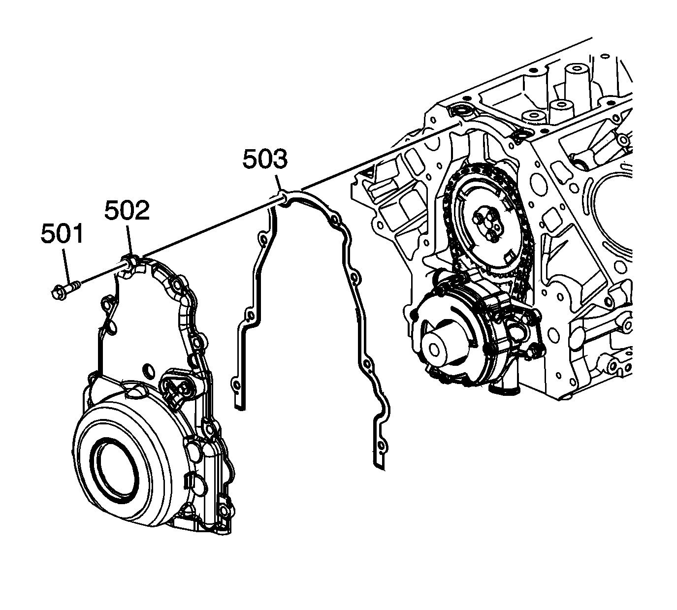
- Remove the front cover bolts (501).
- Remove the front cover (502) and gasket (503). Discard the old gasket.
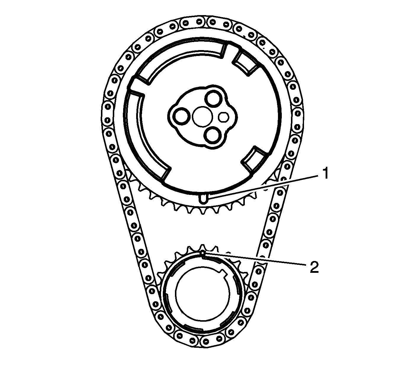
- Rotate the engine in order to align the timing marks (1, 2).
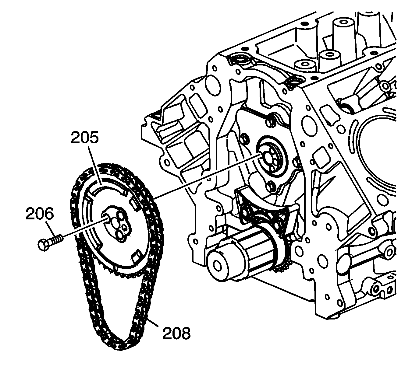
- Remove the camshaft sprocket bolts.
- Remove the timing chain from the camshaft sprocket, and allow the timing chain to rest on the crankshaft sprocket.
- Remove the camshaft. Refer to Camshaft Removal.


Installation Procedure
- Install the camshaft. Refer to Camshaft Installation.
- Align the camshaft sprocket alignment mark in the 6 o'clock position (1).
- Install the camshaft sprocket and timing chain.
- Install the camshaft sprocket bolts and tighten to 30 N·m (22 lb ft).
- Apply a 5 mm (0.2 in) bead of sealant 20 mm (0.8 in) long to the oil pan to engine block junction. Refer to Adhesives, Fluids, Lubricants, and Sealers for the correct part number.
- Install the front cover (502) and a new gasket (503).
- Install the front cover bolts (501) until snug.
- Install the oil pan-to-front cover bolts until snug.
- Install the EN-47812 over the bolt to the crankshaft.
- Install the EN-47813 .
- Insert the tapered surface of the tool into the oil seal bore of the cover EN-47812 washer and nut.
- Remove the tools.
- Install a NEW crankshaft front oil seal. Refer to Crankshaft Front Oil Seal Installation.
- Install the valve lifters. Refer to Valve Lifter Installation.
- Install the right and left cylinder heads. Refer to Cylinder Head Installation - Right Side and Cylinder Head Installation - Left Side.
- Install the valve rocker arms and push rods. Refer to Valve Rocker Arm and Push Rod Installation.
- Install the right and left valve rocker arm covers. Refer to Valve Rocker Arm Cover Installation - Right Side and Valve Rocker Arm Cover Installation - Left Side.
- Install the supercharger. Refer to Supercharger Installation.
- Install the water pump. Refer to Water Pump Installation.
- Install the left and right exhaust manifolds. Refer to Exhaust Manifold Installation - Left Side and Exhaust Manifold Installation - Right Side.
- Install the crankshaft balancer. Refer to Crankshaft Balancer Installation.
- Install the engine assembly. Refer to Engine Replacement.


Recheck the alignment of the timing marks.
Caution: Refer to Fastener Caution in the Preface section.


Tighten the nut by hand until snug. Do not overtighten. Tighten the engine front cover bolts to 30 N·m (22 lb ft).
