Fuel System Diagnosis Fuel Quality
Fuel
Certain driveability problems can be related to fuel quality. The Fuel Related Driveability Problems table lists some of those conditions and which fuel characteristic may be the cause. However, fuel testing is limited. Therefore, all other system checks must be performed (e.g. Powertrain System, Fuel System, Ignition System, Emission System) before fuel quality is diagnosed. If these checks fail to solve the problem, gain information from the customer about when the condition occurs, when and where the fuel was purchased, and which octane level was used. Ask the customer to change fuel brands. If the symptom persists, perform the Fuel System Diagnosis (Alcohol in Fuel) test. If this is not conclusive, drain the tank and refill with a known good quality fuel.
Fuel System Diagnosis Alcohol in Fuel
Alcohol In Fuel
Certain driveability complaints such as hesitation, lack of power, stall, no start, etc. may be caused by an excessive amount of alcohol in fuel. These complaints may be due to fuel system corrosion and subsequent fuel filter plugging, deterioration of rubber components and/or air-fuel mixture leaning.
Various types and concentrations of alcohols are used in commercial fuel. Some alcohols are more detrimental to fuel system components than others. If an excessive amount of alcohol in the fuel is suspected as the cause of a driveability condition, the following procedure may be used to detect the presence of alcohol in the fuel. In this procedure, water is used to extract the alcohol from the fuel. However, the specific type of alcohol (methanol, ethanol or methyl tertiary-butyl ether - MTBE) will not be determined by this procedure.
Testing Procedure
The fuel sample should be drawn from the bottom of the tank so that any water present in the tank will be detected. The sample should be bright and clear. If the sample appears cloudy, or contaminated with water, as indicated by a water layer at the bottom of the sample. This procedure should not be used, and the fuel system should be cleaned refer to Fuel System Cleaning .
- Using a 100 ml cylinder with 1 ml graduation marks, fill with fuel to the 90 ml mark.
- Add 10 ml of water to bring the total fluid volume to 100 ml and install a stopper.
- Shake vigorously for 10-15 seconds.
- Carefully loosen the stopper to release pressure.
- Close the stopper and shake vigorously again for 10-15 seconds.
- Close the stopper and shake vigorously again for 10-15 seconds.
- Carefully loosen the stopper to release pressure.
- Place the graduated cylinder on a level surface for approximately 5 minutes to allow adequate liquid separation.
If alcohol is present in the fuel, the volume of the lower layer (which would now contain both alcohol and water) will be greater than 10 ml. For example, if the volume of the lower layer is increased to 15 ml, it will indicate at least 5 percent alcohol in fuel. The actual amount of alcohol may be somewhat greater because this procedure does not extract all of the alcohol from the fuel.
Fuel System Diagnosis Driveability Problems Table
Symptom | Action |
|---|---|
Poor cold start | Low volatility Injector deposits Refer to Fuel System Diagnosis . |
Poor warm up | Low Volatility |
Poor cold weather performance | Low Volatility |
Poor hot start | High Volatility |
Poor hot weather performance | High Volatility |
Vapor lock | High Volatility |
Spark/detonation | Low octane |
Poor fuel economy | High volatility Injector deposits Refer to Fuel System Diagnosis . Intake valve deposits Refer to Fuel System Diagnosis . Low octane |
Excessive exhaust emissions | Low volatility Sulfur deposits Injector deposits Refer to Fuel System Diagnosis . Intake valve deposits Refer to Fuel System Diagnosis . |
Reduced Power | Low octane Intake valve deposits Refer to Fuel System Diagnosis . Injector deposits Improper volitility |
Rough/unstable idle | Injector deposits Refer to Fuel System Diagnosis . |
Always begin the fuel and the air control system diagnosis with, Fuel System Check. This chart will identify other charts for specific checks, such as:
| • | Fuel Pressure Check |
| • | Injector Flow/Voltage Drop Check |
| • | Power Balance Check |
| • | Idle Speed Control Check |
Fuel System Diagnosis Fuel System Check
Circuit Description
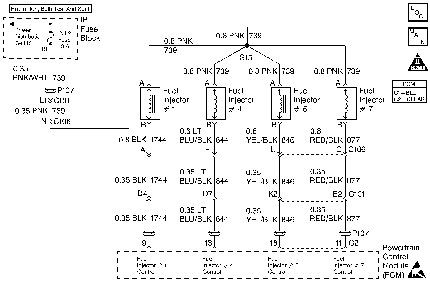
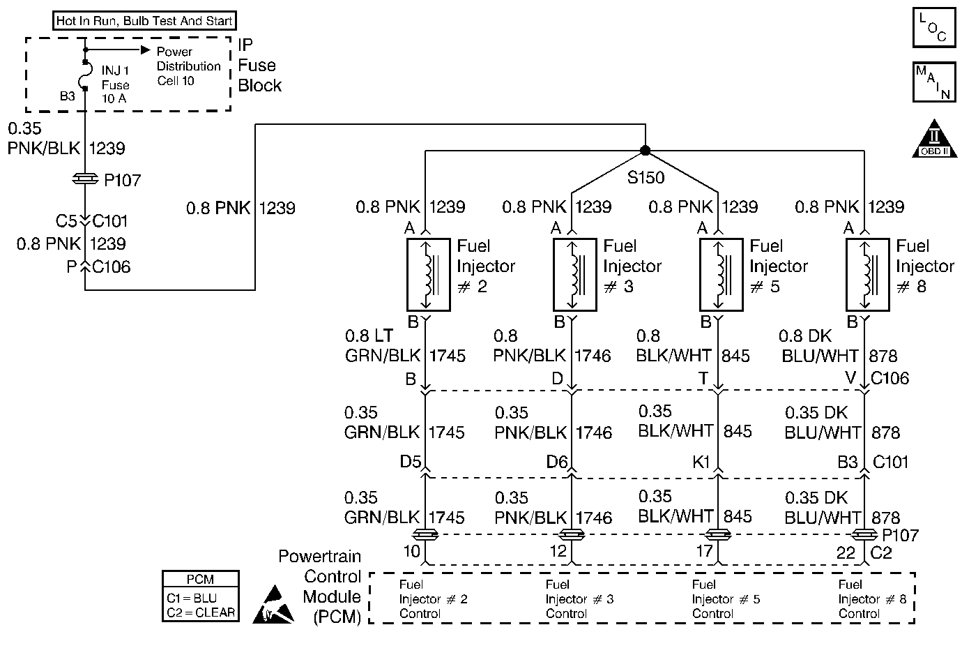
Refer to

and

for an electrical diagram of this circuit.
The Fuel System Check provides a quick analysis of the fuel system. This chart then identifies more detailed diagnosis required based on the symptoms present.
The Fuel Leak/Odor Check provides a means of identifying a fuel system component that is causing a leak. This also provides information on how to diagnosis a fuel odor condition.
Diagnostic Aids
| • | Nylon fuel lines are not repairable and must be replaced. |
| • | Evaporative Emission Control (EVAP) system problems may cause a fuel odor condition. |
| • | Rich engine operation may also cause a fuel odor condition. |
| • | Check all component and circuit grounds. |
Test Description
Number(s) below refer to the step number(s) on the Diagnostic Table.
-
If the engine does not start or stay running and there is no fuel pressure check all components and circuit grounds.
-
The vehicle should be operated the same conditions as when the leak/odor occurs.
Step | Action | Value(s) | Yes | No |
|---|---|---|---|---|
1 | Was the Powertrain On-Board Diagnostic (OBD) System Check performed? | -- | Go to A Powertrain On Board Diagnostic (OBD) System Check | |
2 | Were you sent here from a DTC table? | -- | ||
3 | Key On install the Scan Tool. Are any PCM DTC(s) set? | -- | Diagnose those DTC(s) first | |
Crank the engine. Does the engine start and stay running? | -- | Go to Fuel System Pressure Test | ||
Is there a fuel leak or odor complaint? | -- | |||
6 | Is there a fuel odor complaint? | -- | ||
7 | Is there a fuel gage complaint? | -- | Go to Electrical Diagnosis Instrument Panel Displays | |
8 | Is there a economy complaint? | -- | Go to Poor Fuel Economy | |
9 | Are there any other driveability symptoms? | -- | Go to Fuel System Pressure Test | Fuel System OK |
10 | Try to duplicate customer complaint. Is there a fuel leak? | -- | Go to Excessive Exhaust Emissions or Odors | |
11 | Try to duplicate customer complaint. Is there a fuel odor? | -- | Go to Excessive Exhaust Emissions or Odors | Fuel system OK |
12 | Repair fuel leak. Is the repair complete? | -- | Go to A Powertrain On Board Diagnostic (OBD) System Check | -- |
Fuel System Diagnosis Idle Speed Control Check
Circuit Description
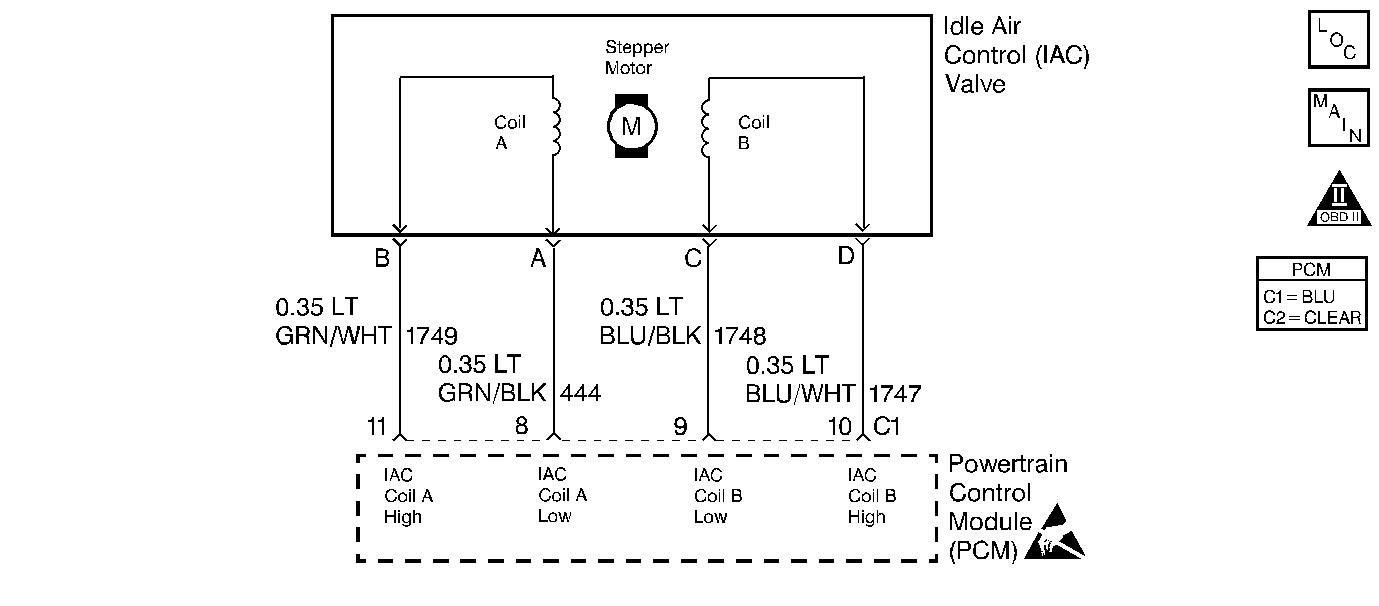
Refer to

for an electrical diagram of this circuit.
The Idle Speed Control Check verifies proper IAC valve operation.
Test Description
Number(s) below refer to the step number(s) on the Diagnostic Table.
-
This check test the IAC valve to make sure that it is moving in and out without binding. Follow PCM DTC P1508 diagnosis to identify the cause of a faulty IAC valve.
-
This procedure checks for high minimum air idle which could cause a high idle at closed throttle. It is OK if the engine cannot stay running at minimum air idle.
-
This procedure checks for IAC ability to increase idle speed.
Step | Action | Value(s) | Yes | No |
|---|---|---|---|---|
1 | Was the Powertrain On-Board Diagnostic (OBD) System Check performed? | -- | Go to A Powertrain On Board Diagnostic (OBD) System Check | |
2 | Were you sent here from a DTC table? | -- | ||
3 |
Are any PCM DTC(s) set? | -- | Diagnosis those DTC(s) first | |
Does the Engine Speed remain within the specified value of Desired Idle for each RPM command? | 50 RPM | Go to DTC P1508 Idle Speed Low - Idle Air Control (IAC) System Not Responding | ||
Command IAC to minimum RPM (full closed position). Is idle above the value specified? | 500 RPM | |||
6 |
Was a leak found and repaired? | -- | System OK | |
Command IAC to maximum RPM (full open position). Is idle below the value specified? | 1500 RPM | System OK | ||
8 | Replace IAC valve. Refer to Idle Air Control Valve Replacement . Is repair complete? | -- | System OK | -- |
9 | Replace throttle body. Refer to Throttle Body Assembly Replacement . Is the repair complete? | System OK | Go to A Powertrain On Board Diagnostic (OBD) System Check |
Fuel System Diagnosis Power Balance Check
Circuit Description
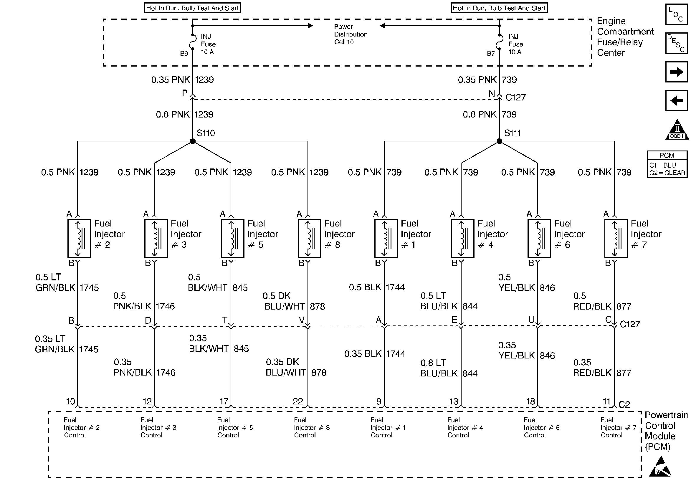
Refer to
Fuel Injectors

for an electrical diagram of this circuit.
The Fuel Injector Balance Test compares the performance of each of the cylinder by using the PCM to shut off fuel injection. This measures the performance of each cylinder by the amount of RPM drop caused by that cylinder not producing a power stroke. If proper fuel delivery has been determined, then a cylinder that does not show good performance (RPM drop) indicates either an ignition or mechanical problem.
Test Description
Number(s) below refer to the step number(s) on the Diagnostic Table.
Step | Action | Value(s) | Yes | No |
|---|---|---|---|---|
1 | Was the Powertrain On-Board Diagnostic (OBD) System Check performed? | -- | Go to A Powertrain On Board Diagnostic (OBD) System Check | |
2 | Has the Fuel System Check been performed? | -- | Go to Fuel System Diagnosis (Fuel System Check) | |
Were engine speed and idle quality changes for all cylinders equal? | -- | Go to EVAP Control System Diagnosis | Go to Electronic Ignition (EI) System Diagnosis (Ignition System Check) |
Fuel System Diagnosis Injector Flow Drop Check
Refer to
Fuel Injectors

for an electrical diagram of this circuit.
The Injector Flow/Voltage Drop Check compares the fuel pressure drop when each injector is pulsed for a set amount of time. Since each injector is pulsed the same, the fuel pressure drop for each injector should be approximately the same. Suspect fuel injectors can be identified by either too high or too low fuel pressure drop. This check also determines if the voltage drop of the injector is within specification. Injector voltage drop out of specification can cause driveability conditions that are intermittent or that do not show up during an injector flow check.
Tools Required
J 34730-1A Fuel Pressure Gauge, J 39200 Voltmeter, J 39021 Fuel Injector Tester.
Test Description
Number(s) below refer to the step number(s) on the Diagnostic Table.
-
Commanding the fuel pump on for 5 seconds will energize the fuel pump to build fuel pressure. Then selecting individual injectors will allow you to see the fuel pressure drop associated with each injector. If all eight injectors drop some pressure then the circuit is not open. Any injector that drops no pressure has an open in the circuit or a faulty injector.
-
Checking if a fuse was open causing either injectors 2, 3, 5, 8, or 1, 4, 6 and 7 not to operate.
-
Checking if CKT 739 or CKT 1239 is open from the fuse to C127.
Step | Action | Value(s) | Yes | No |
|---|---|---|---|---|
1 | Was the Powertrain On-Board Diagnostic (OBD) System Check performed? | -- | Go to A Powertrain On Board Diagnostic (OBD) System Check | |
2 | Has the Fuel System Check been performed? | -- | Go to Fuel System Diagnosis (Fuel System Check) | |
Does fuel pressure drop when each injector is tested? | -- | |||
4 | Do two or more fuel injectors have no pressure drop? | -- | ||
Are both fuses OK? | -- | |||
6 |
Do both pins measure greater than 10 volts? | -- | ||
7 | Select Coil Test on fuel injector tester and test all injectors. Did voltage reading for any injector exceed the specified value? | 9.5V | ||
8 | Inspect the highest reading and subtract the specified value. Was the voltage for any injector less than this value (more than .55 volts less than the highest)? | 0.55V | ||
9 | Have any injectors been replaced up to this point? | -- | ||
10 | Were the fuel pressure drops recorded in step 2 for all injectors within the specified value? | 2 PSI | Go to Fuel System Diagnosis | |
11 | Select Coil Test on the fuel injector tester and test injector which had no fuel pressure drop. Does coil test voltage measure between the specified value? | 5.74-7.0 V | ||
12 |
Does voltage measure the same or greater than the specified value? | 10V | ||
13 | Check fuel rail harness for opens or shorts in suspect injector circuits. Open or short found? | -- | ||
14 | Check CKT(s) 739 and 1239 for shorts to ground. Was a short found? | -- | ||
15 | Measure resistance at the fuel rail connector (fuel rail side) across suspect injector circuits. Do any measure less than the first specified value or greater than the second specified value? | 8 to 25 ohms | ||
16 | Connect fuel injector tester to suspect injector(s) and select Coil Test. Does voltage reading from coil test measure between the specified values? | 5.74-7V | ||
17 | Repair open CKT 739 or CKT 1239 between the fuse and the fuel rail connector. Was a repair made? | -- | Go to A Powertrain On Board Diagnostic (OBD) System Check | -- |
18 | Replace injector(s) whose voltage reading exceeded the specified valve. Was a repair made? | -- | Go to A Powertrain On Board Diagnostic (OBD) System Check | -- |
19 | Replace injector(s) whose voltage reading was more than 0.55 volts less than the highest voltage reading Was a repair made? | -- | Go to A Powertrain On Board Diagnostic (OBD) System Check | -- |
20 | Duplicate conditions under which customer complaint occurred and verify proper operation. Is the system operating OK? | -- | System OK | -- |
21 | Replace injector(s) whose pressure drop was not within the specified value of the others. Was a repair made? | -- | Go to A Powertrain On Board Diagnostic (OBD) System Check | -- |
22 | Check PCM terminal contact and if OK, replace the PCM, refer to PCM Replacement/Programming . Was a repair made? | -- | Go to A Powertrain On Board Diagnostic (OBD) System Check | -- |
23 | Repair open between the fuel rail connector and the PCM in suspect circuit. Was a repair made? | -- | Go to A Powertrain On Board Diagnostic (OBD) System Check | -- |
24 | Repair circuit. Was a repair made? | -- | Go to A Powertrain On Board Diagnostic (OBD) System Check | -- |
25 | Replace injector. Was a repair made? | -- | Go to A Powertrain On Board Diagnostic (OBD) System Check | -- |
26 | Repair short and replace blown fuse. Was a repair made? | -- | Go to A Powertrain On Board Diagnostic (OBD) System Check | -- |
27 | Replace blown fuse. Was a repair made? | -- | Go to A Powertrain On Board Diagnostic (OBD) System Check | -- |
28 | Repair fuel rail harness for suspect injector. Was a repair made? | -- | Go to A Powertrain On Board Diagnostic (OBD) System Check | -- |
29 | Replace suspect injector. Was a repair made? | -- | Go to A Powertrain On Board Diagnostic (OBD) System Check | -- |
Fuel System Diagnosis Fuel System Deposits
Fuel System Deposits
Fuel system deposits can cause various driveability problems. Deposits usually occur during hot soaks after key Off. Poor fuel quality or driving patterns such as short trips followed by long cool down periods can cause injector deposits. This occurs when the fuel remaining in the injector tip evaporates and leaves deposits. Leaking injectors can increase injector deposits. Deposits on fuel injectors affect their spray pattern, which in turn could cause reduced power, unstable idle, hard starts and poor fuel economy.
Intake valve deposits can also be related to fuel quality. While most fuels contain deposit inhibitors, some do not and the effectiveness of deposit inhibitors varies by manufacturer. If intake valve deposits occur, fuel may be suspected. These deposits can cause symptoms such as excessive exhaust emissions, power loss and poor fuel economy.
