For 1990-2009 cars only
Special Tools
| • | J 38185 Hose Clamp Pliers |
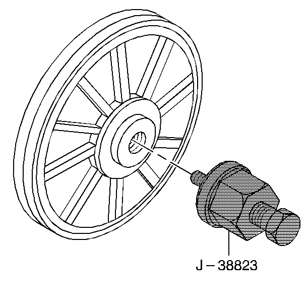
| • | J 38823 Water Pump Drive Pulley Installer |
| • | J 38825 Water Pump Drive Pulley Remover |
Removal Procedure
- Remove the fuel injector sight shield. Refer to Fuel Injector Sight Shield Replacement .
- Partially drain the cooling system. Refer to Cooling System Draining and Filling .
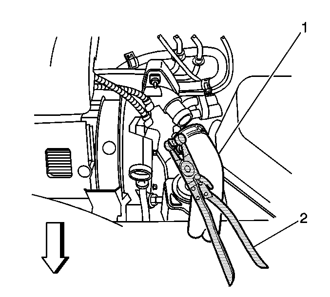
- Position the J 38185 (2) to the clamp in order to remove the radiator inlet hose (1) from the water housing crossover.
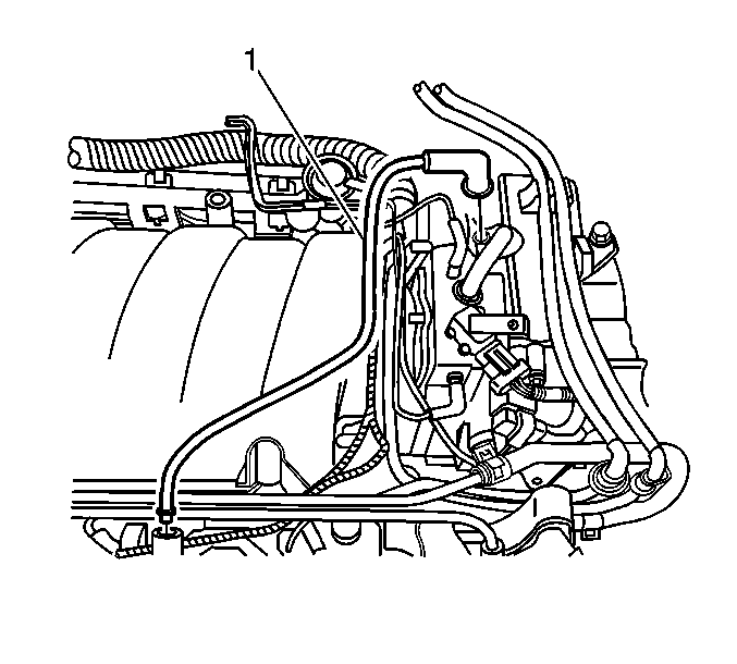
- Disconnect the PCV fresh air tube (1) from the camshaft cover.
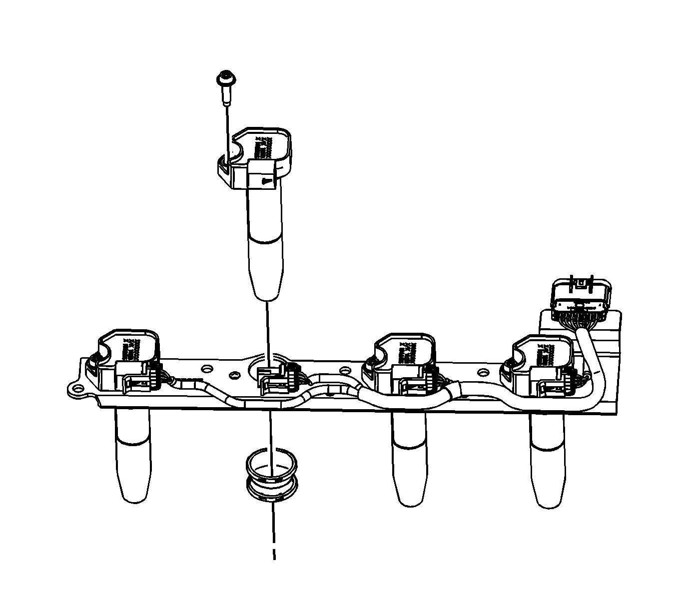
- Remove the ignition coils. Refer to Ignition Coil Replacement - Bank 2 .
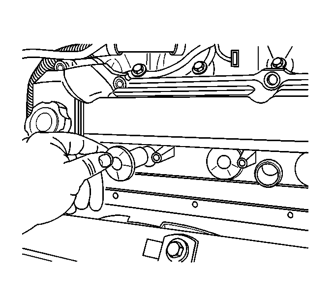
- Remove the 4 spark plug boots.
- Disconnect the cable harness clips at the front of the camshaft cover and position the cable harness aside.
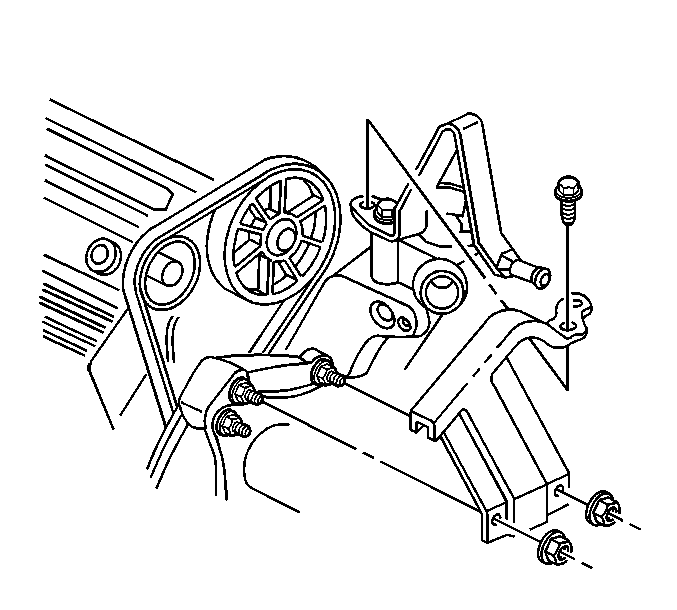
- Remove the secondary AIR valve bracket nut closest to the center of the engine.
- Pry outward slightly on the secondary AIR valve bracket in order to gain clearance to remove the water pump drive belt shield nut.
- Remove the water pump drive belt shield fasteners.
- Remove the water pump drive belt shield.
- Disconnect the water pump drive belt.
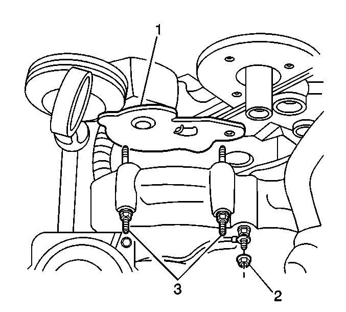
- Loosen the 2 bolts (3) attaching the water pump belt tensioner (1) to the water crossover.
- Remove the water pump belt tensioner (1).
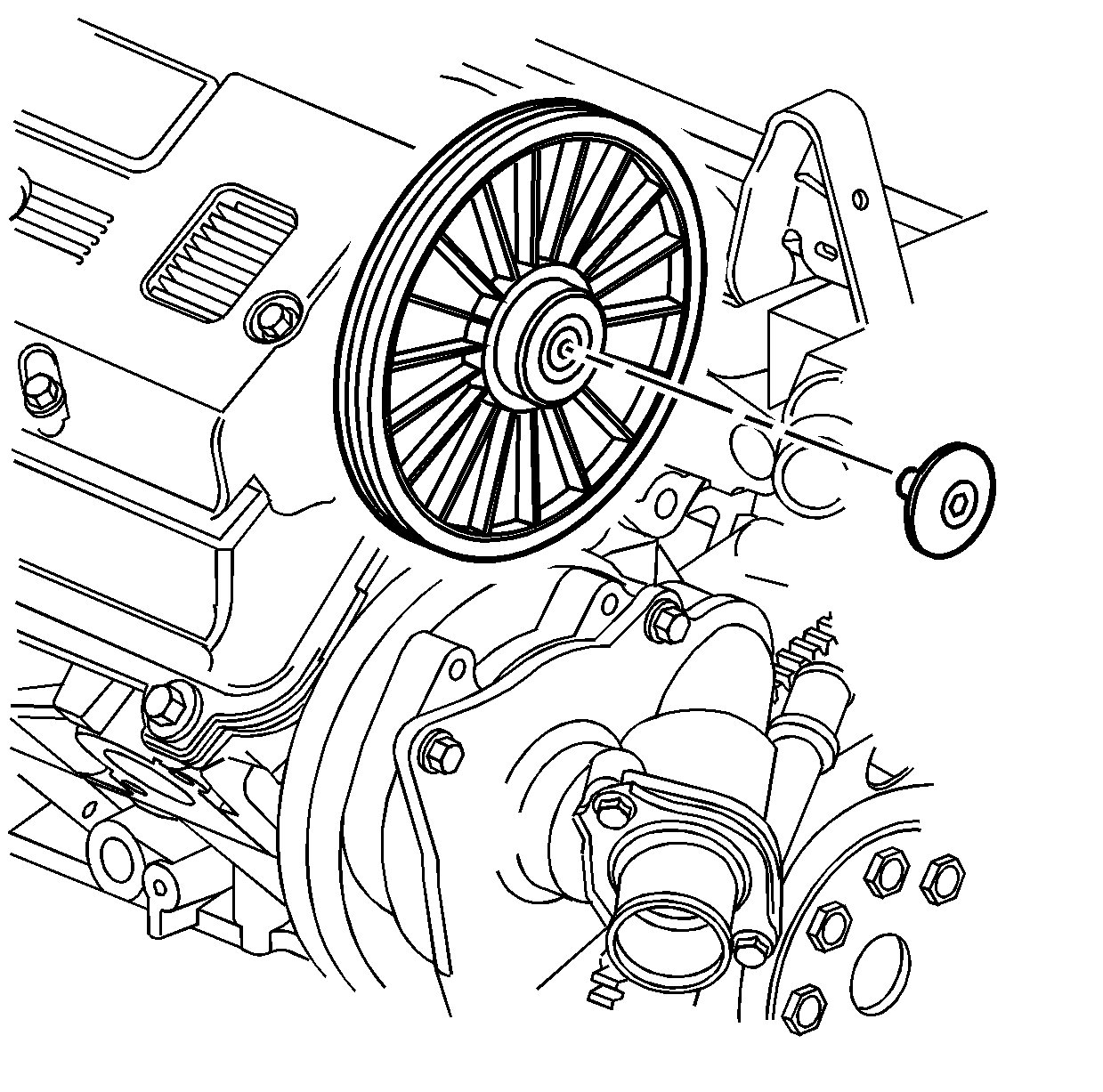
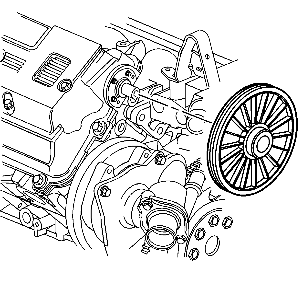
- Remove the plastic dust cap from the end of the intake camshaft.
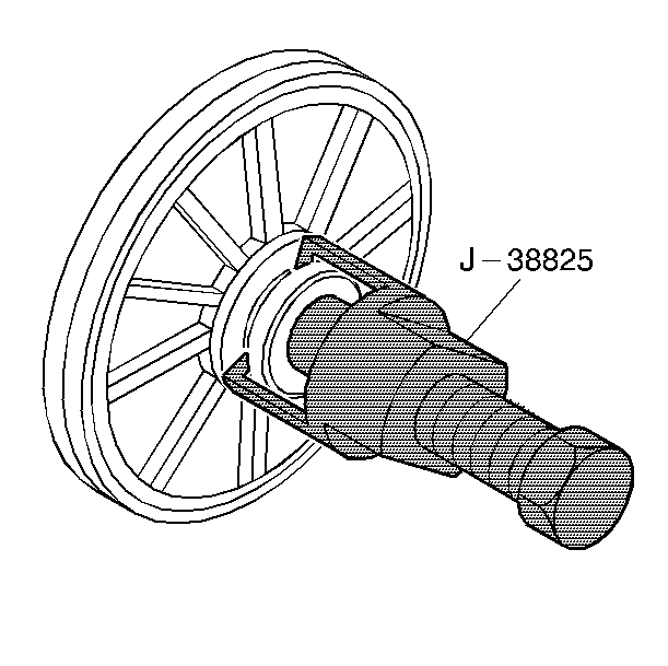
- Remove the water pump drive pulley from the intake camshaft using the J 38825 .
- Remove the 3 camshaft seal retainer bolts.
- Remove the camshaft seal.
- Disconnect the engine ground strap. Refer to Engine Ground Strap Replacement .
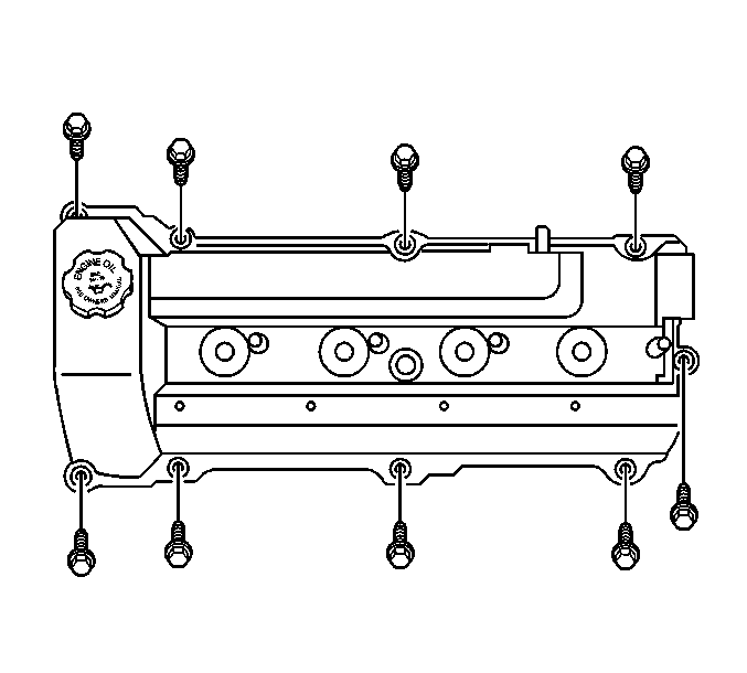
- Remove the camshaft cover bolts.
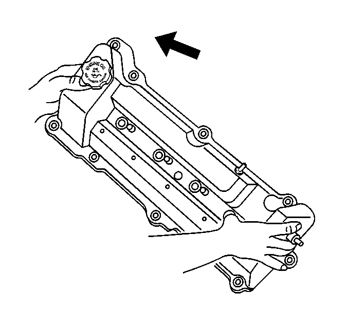
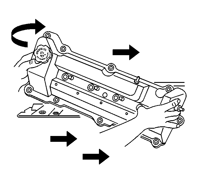
- Lift the camshaft drive end of the camshaft cover up.
- Remove the camshaft cover reward to clear the water pump drive shaft.
- Discard the camshaft cover perimeter seals and spark plug seals if there is any evidence of damage or if the seal comes out of the groove in the cover during removal.
- Clean and inspect the camshaft cover. Refer to Camshaft Cover Cleaning and Inspection .
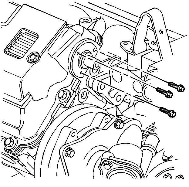
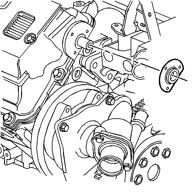
Important: DO NOT reuse the camshaft seal.
Installation Procedure
- Install the camshaft cover seal as required.
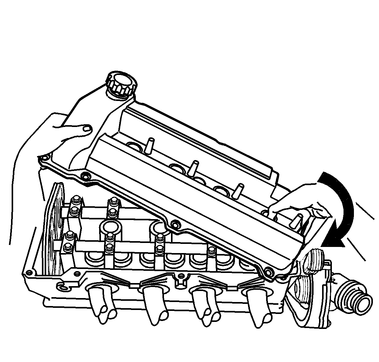
- Insert the intake camshaft end through the hole in the camshaft cover.
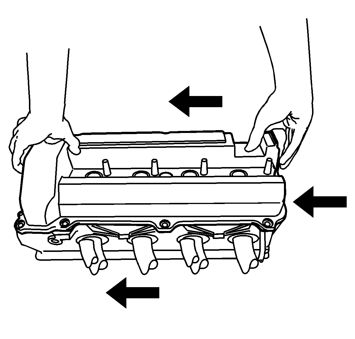
- Work the camshaft cover into position by pivoting the cover down and to the left allowing the cover to clear the camshaft drive chain and then aligning the bolt holes.
- Install the 9 camshaft cover bolts.
- Connect the engine ground strap. Refer to Engine Ground Strap Replacement .
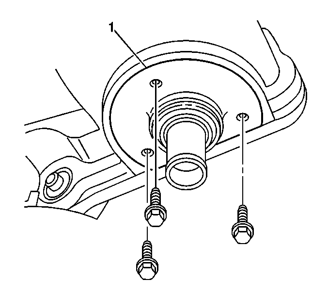
- Install the NEW seal as follows:
- Coat the bolt threads with sealant GM P/N 1052080 (Canadian P/N 10953480) or equivalent.
- Install the camshaft seal (1) bolts.
- Place the water pump drive pulley in position on the intake camshaft.
- Install the water pump pulley using the J 38823 . During installation, the tool will bottom out on the camshaft at the proper depth.
- Install the plastic dust cap into the end of the camshaft.
- Position the water pump belt tensioner (1) to the water crossover.
- Connect the water pump drive belt.
- Install the water pump drive belt shield.
- Install the water pump drive belt shield fasteners.
- Connect the cable harness clips to the cable harness at the front of the camshaft cover.
- Ensure that the spark plug seals are in position.
- Install the ignition coils. Refer to Ignition Coil Replacement - Bank 2 .
- Connect the PCV fresh air tube (1) to the left camshaft cover.
- Position the J 38185 (2) to the clamp in order to connect the radiator inlet hose (1) to the water housing crossover.
- Install the fuel injector sight shield. Refer to Fuel Injector Sight Shield Replacement .
- Fill the cooling system. Refer to Cooling System Draining and Filling .
Important: Be careful to prevent the exposed section of the camshaft cover seal from being damaged by the edge of the cylinder head casting.
Notice: Refer to Fastener Notice in the Preface section.

Tighten
Tighten the camshaft cover bolts to 10 N·m (89 lb in).

| 6.1. | Lubricate the camshaft seal lips with engine oil. |
| 6.2. | Push the camshaft seal into position around the intake camshaft using the protective sleeve supplied with the seal. |
Tighten
Tighten the camshaft seal bolts to 3 N·m (27 lb in).


Tighten
Tighten the water pump belt tensioner bolts (3) to 10 N·m (89 lb in).

Tighten
| • | Tighten the water pump drive belt shield fasteners to 10 N·m (89 lb in). |
| • | Tighten the secondary AIR valve bracket nut to 9 N·m (80 lb in). |
