Circuit Description
The CVRSS module estimates the road surface and communicates that information to the Electronic Brake and Traction Control Module (EBTCM) using the ICCS2 Datalink Left and Right Outputs. The EBTCM uses this information to provide improved rough-road braking performance.
Conditions for Setting the DTC
The DTC is set when the CVRSS module measures a feedback voltage less than a preset threshold during an ICCS2 Datalink Left Output OFF state.
The DTC turns HISTORY when the CVRSS module no longer senses a low feedback voltage during five (5) consecutive ICCS2 Datalink Left Output OFF states.
Action Taken When the DTC Sets
| • | Both of the ICCS2 Datalink Outputs are set to default output states. |
| • | The SERVICE RIDE CONTROL message will be displayed. |
Conditions for Clearing the MIL/DTC
| • | Use the scan tool. |
| • | Use the On-Board diagnostic CLEAR RSS CODES feature. |
Test Description
Important:
• Do not backprobe the sensors, actuators, or any sealed connectors. • When all the diagnostics and repairs are complete, clear the DTCs
and verify the operation.
The number(s) below refer to the step number(s) on the diagnostic table.
-
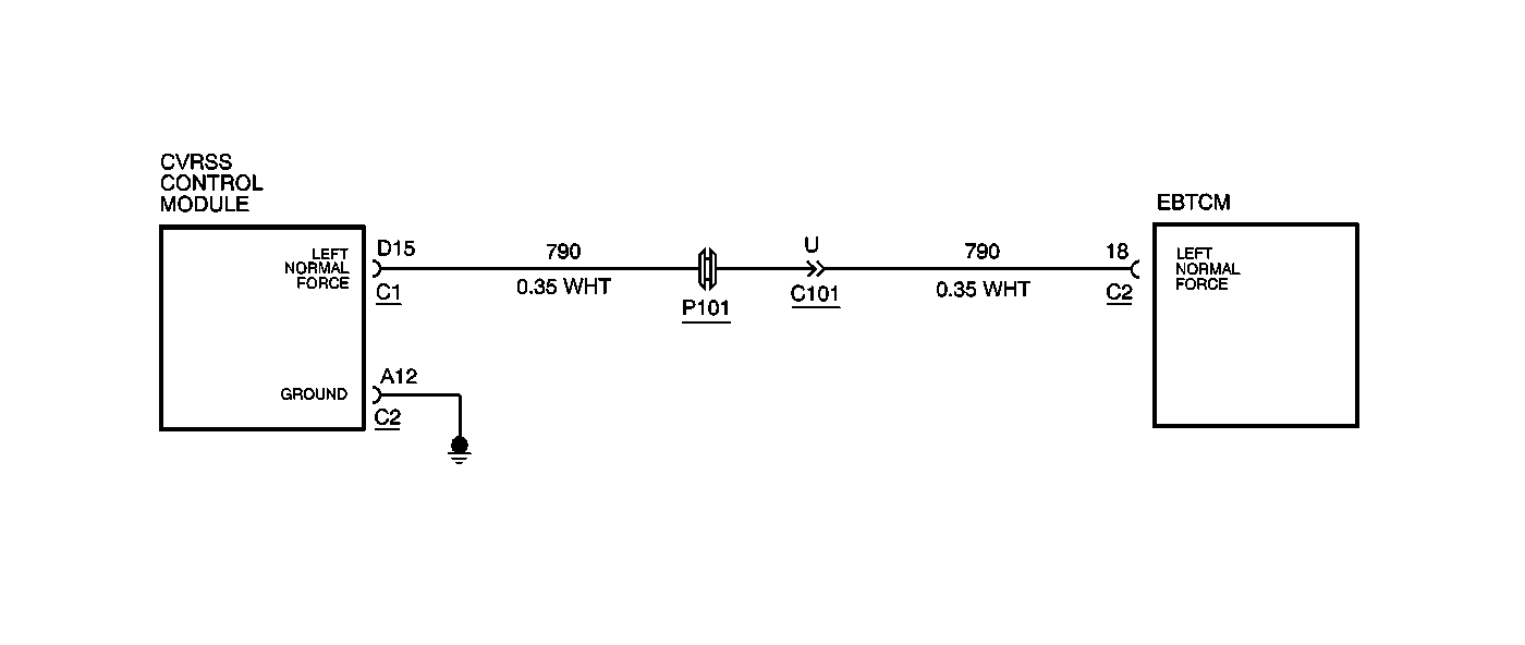
This step determines if the fault is due to a short circuit to ground condition or an open circuit condition in CKT 790 and determines if the short circuit to ground condition is in the wiring or with the EBTCM.
-
This step checks for an open circuit condition in CKT 790.
-
This step checks for a short circuit to ground condition in CKT 790.
Step | Action | Value(s) | Yes | No |
|---|---|---|---|---|
1 | Was the Road Sensing Suspension Diagnostic System Check performed? | -- | Go to Step 2 | |
Is the voltage greater than the specified value? | 10 V | Go to Step 7 | Go to Step 3 | |
Is the resistance equal to or less than the specified value? | 5 ohms | Go to Step 4 | Go to Step 5 | |
Measure the resistance between CVRSS module connector C1, terminal D15, and ground with a DMM. Is the resistance the specified value? | OL | Go to Step 8 | Go to Step 6 | |
5 | Repair the open circuit condition or poor connection condition in CKT 790. Is the repair complete? | -- | -- | |
6 | Repair the short circuit to ground condition in CKT 790. Is the repair complete? | -- | -- | |
7 |
Important: The controller must be calibrated. Is the CVRSS control module calibrated? | -- | -- | |
8 |
Is the repair complete? | -- | -- |
