Removal Procedure
Caution: Refer to SIR Handling Caution in the Preface section.
- Disconnect the negative battery cable. Refer to Battery Negative Cable Disconnection and Connection in Engine Electrical.
- Disable the SIR. Refer to Disabling the SIR System in SIR.
- Remove the center console. Refer to Console Replacement .
- Remove the instrument panel (IP) center trim plate. Refer to Instrument Panel Center Trim Panel Replacement .
- Remove the radio. Refer to Radio Replacement in Entertainment.
- Remove the HVAC control assembly. Refer to HVAC Control Module Replacement in HVAC Automatic.
- Remove the right and the left sound insulators. Refer to Instrument Panel Insulator Panel Replacement - Right Side .
- Remove the IP outer trim covers. Refer to Instrument Panel Outer Trim Cover Replacement .
- Remove the IP upper trim pad. Refer to Instrument Panel Upper Trim Pad Replacement .
- Remove the defroster grille. Refer to Defroster Grille Replacement .
- Remove the knee bolster. Refer to Knee Bolster Replacement .
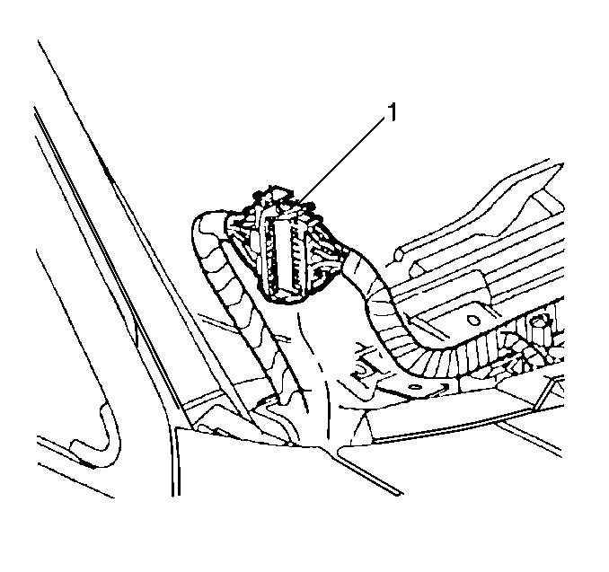
- Disconnect the body-to-IP electrical connectors (1) at the top outside corners of the IP.
- Remove the steering column. Refer to Steering Column Replacement in Steering Wheel and Column.
- For RHD (Right Hand Drive) only, Remove the park brake cable from the park brake pedal assembly. Refer to Parking Brake Lever Pedal Assembly Replacement in Parking Brakes.
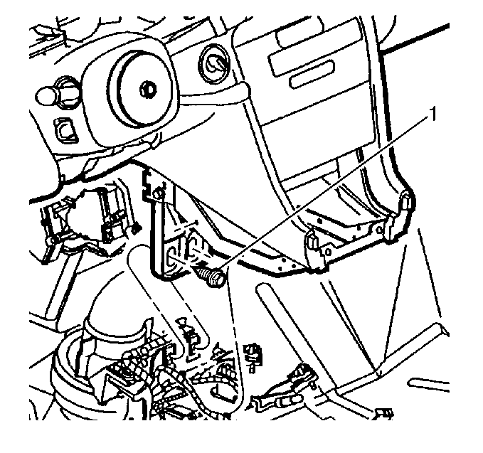
- Remove the IP extension bolts (1).
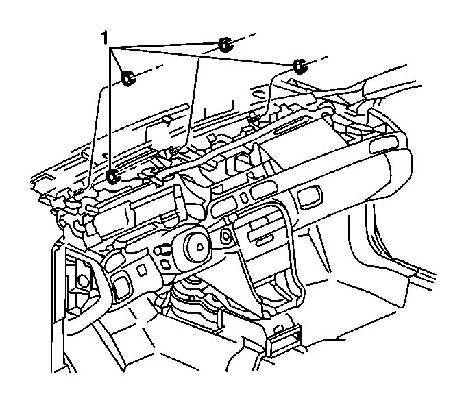
- Remove the IP carrier to the cowl nuts (1).
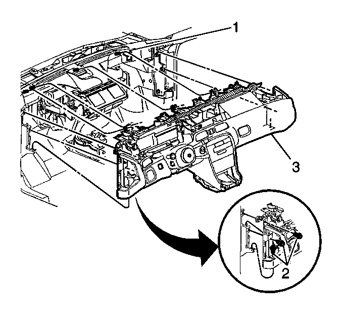
- Remove the 6 bolts (2) from the IP carrier to the hinge pillar. (Three bolts are on the left hinge pillar and 3 bolts are on the right hinge pillar) (3).
- Remove the IP carrier from the vehicle.
- Remove the IP cluster trim panel. Refer to Instrument Cluster Trim Panel Replacement .
- Remove the passenger side inflator module from the IP retainer. Refer to Inflatable Restraint Instrument Panel Module Replacement .
- Remove the left trim plate. Refer to Instrument Panel Accessory Trim Plate Replacement - Left Side .
- Remove the IP cluster. Refer to Instrument Cluster Replacement .
- Remove the right IP trim plate from the IP carrier. Refer to Instrument Panel Accessory Trim Plate Replacement - Right Side .
- Remove the ignition switch from the IP. Refer to Ignition and Start Switch Replacement .
- Remove the headlamp lamp switch. Refer to Headlamp Switch Replacement in Lighting Systems.
- Remove the fuel door/rear compartment release switch. Refer to Rear Compartment Lid Switch Replacement in Body Rear End.
- Remove the IP storage compartment from the IP. Refer to Instrument Panel Compartment Replacement .
- Remove the bolts that retain the IP retainer to the carrier.
- Partially remove the IP retainer from the carrier.
- Disconnect the inside air temperature sensor electrical connector.
- Remove the inside temperature sensor from the IP retainer. Refer to Inside Air Temperature Sensor Replacement in HVAC Automatic.
- Disconnect the park lock cable from the IP. Refer to Park Lock Cable Replacement in Automatic Transmission.
- Remove the A/C temperature sensors from the left and the right air distribution ducts. Refer to HVAC Control Module Replacement in HVAC System-Automatic.
- Remove the bolts that retain the left and the right air distribution ducts.
- Remove the screws from the left and the right side window defroster ducts.
- Remove the theft deterrent module and the mounting bracket from the IP carrier. Refer to Theft Deterrent Module Replacement in Theft Deterrent.
- Remove the IP wiring harness from the IP carrier.
- Remove the slip bracket bolts (1).
Caution: Refer to Battery Disconnect Caution in the Preface section.
Guide the wiring through the openings.
Remove the IP retainer from the vehicle.
Remove the air distribution ducts from the vehicle.
Remove the left and right side window defroster ducts.
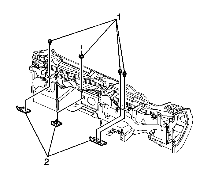
Remove the slip brackets (2) from the IP carrier.
Installation Procedure
- Install the slip brackets (2) to the IP carrier.
- Install the IP wiring harness to the IP carrier.
- Install the park brake assembly to the carrier. Refer to Parking Brake Lever Pedal Assembly Replacement in Parking Brakes.
- Install the theft deterrent module and the mounting bracket to the IP carrier. Refer to Theft Deterrent Module Replacement in Theft Deterrent.
- Install the left and the right side window defroster ducts.
- Install the bolts fully driven, seated but not stripped.
- Install the left and the right air distribution ducts.
- Install the bolts fully driven, seated, but not stripped.
- Install the A/C temperature sensors to the left and the right air distribution ducts. Refer to Ambient Air Temperature Sensor Replacement in HVAC System--Automatic.
- Connect the park lock cable to the IP. Refer to Park Lock Cable Replacement in Automatic Transmission.
- Install the inside temperature sensor to the IP retainer. Refer to Inside Air Temperature Sensor Replacement in HVAC Automatic.
- Install the ignition switch to the IP. Refer to Ignition and Start Switch Replacement .
- Partially install the IP retainer.
- Guide the wiring through the openings.
- Complete the IP retainer Installation.
- Install the IP retainer to the IP carrier bolts.
- Install the IP storage compartment. Refer to Instrument Panel Compartment Replacement .
- Install the fuel door/rear compartment release switch. Refer to Rear Compartment Lid Switch Replacement in Body Rear End.
- Install the headlamp switch. Refer to Headlamp Switch Replacement in Lighting Systems.
- Install the right IP trim plate to the IP carrier. Refer to Instrument Panel Accessory Trim Plate Replacement - Right Side .
- Install the IP cluster. Refer to Instrument Cluster Replacement .
- Install the left trim plate. Refer to Instrument Panel Accessory Trim Plate Replacement - Left Side .
- Install the passenger side inflator module to the IP retainer. Refer to Inflatable Restraint Instrument Panel Module Replacement in SIR.
- Install the IP cluster trim panel to the IP carrier. Refer to Instrument Cluster Trim Panel Replacement .
- Install the IP carrier (3) to the vehicle.
- Install the bolts (2) from the IP carrier to the hinge pillar.
- Install the IP carrier to the cowl nuts (1).
- Tighten the previously installed bolts to the slip brackets.
- Install the bolts (1) from the steering column support (2) to the IP carrier.
- Install the IP center support bracket bolts (1) to the floor bracket.
- Connect the front parking brake cable housing to the parking brake pedal assembly. Refer to Parking Brake Lever Pedal Assembly Replacement in Parking Brakes.
- Install the steering column. Refer to Steering Column Replacement in Steering Wheel and Column.
- Connect the cigar lighter/ashtray lamp harness retainer push pin to the retaining bracket.
- Connect the HVAC harness electrical connector.
- Connect the body to IP electrical connectors (1) at the top outside corners of the IP.
- Install the knee bolster. Refer to Knee Bolster Replacement .
- Install the defroster grille. Refer to Defroster Grille Replacement .
- Install the IP upper trim pad. Refer to Instrument Panel Upper Trim Pad Replacement .
- Install the IP outer trim covers. Refer to Instrument Panel Outer Trim Cover Replacement .
- Install the right and the left sound insulators. Refer to Instrument Panel Insulator Panel Replacement - Right Side .
- Install the HVAC control assembly. Refer to HVAC Control Module Replacement in HVAC Automatic.
- Install the radio. Refer to Radio Replacement in Entertainment.
- Install the IP center trim plate. Refer to Instrument Panel Center Trim Panel Replacement .
- Install the center console. Refer to Console Replacement .
- Enable the SIR. Refer to Enabling the SIR System in SIR.
- Connect the negative battery cable. Refer to Battery Negative Cable Disconnection and Connection in Engine Electrical.

Loosely install the slip bracket bolts (1).
Notice: Refer to Fastener Notice in the Preface section.
Connect the inside air temperature sensor electrical connector.

Tighten
Tighten the IP carrier nuts to 25 N·m (18 lb ft).

Tighten
Tighten the carrier to the cowl nuts (1) to 25 N·m
(18 lb ft).
Tighten
Tighten the bracket bolts to 25 N·m (18 lb ft).
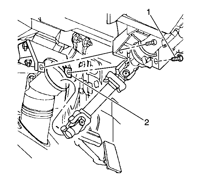
Tighten
Tighten the bolts to 9 N·m (7 lb ft).

Tighten
Tighten the IP center support bracket bolts to 25 N·m
(18 lb ft).

