For 1990-2009 cars only
Tools Required
| • | J 45059 Angle Meter |
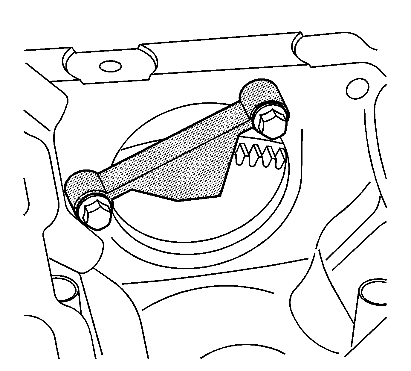
| • | EN 46326 Crankshaft Holding Tool |
Removal Procedure
- Remove the powertrain. Refer to Powertrain Removal and Installation .
- Remove the driveline support assembly. Refer to Driveline Support Assembly Replacement in Propeller Shaft.
- Remove the intake manifold. Refer to Intake Manifold Replacement .
- Install the EN 46326 .
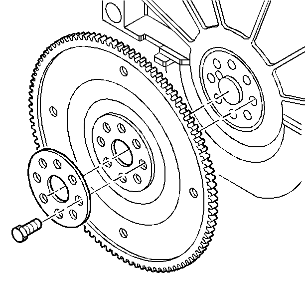
- Remove the engine flywheel bolts.
- Remove the flywheel and the reinforcement.
- Clean and inspect the engine flywheel. Refer to Engine Flywheel Cleaning and Inspection .


Installation Procedure
- Apply sealant to the flywheel mounting bolts. Refer to Adhesives, Fluids, Lubricants, and Sealers for the correct part number.
- Position the flywheel and the reinforcement to the crankshaft.
- Install the flywheel mounting bolts.
- Remove the EN 46326 .
- Install the intake manifold. Refer to Intake Manifold Replacement .
- Install the driveline support assembly. Refer to Driveline Support Assembly Replacement in Propeller Shaft.
- Install the powertrain. Refer to Powertrain Removal and Installation .

Notice: Refer to Fastener Notice in the Preface section.
| 3.1. | First Pass |
Tighten
Tighten the flywheel mounting bolts to 15 N·m (11 lb ft).
| 3.2. | Final Pass |
Tighten the flywheel mounting bolts an additional 50 degrees using the J 45059 .

