Removal Procedure
Tools Required
| • | J 41602 Body
Protection Hoist Adapter Set |
| • | J 39580 Universal
Engine Support Table |
Important
This procedure must be performed on a side lift hoist. The engine and
front frame assembly will be removed out of the bottom of the vehicle, therefore,
a single post hoist or a twin post hoist cannot be used to perform
this procedure.
Notice: Failure to flush out the oil cooling system or the engine cooling system
may result in premature failure of the replacement engine.
If the engine is damaged internally and a new engine is installed, make
sure that all foreign material is completely flushed out of the cooling system.
The oil cooler system should be also be flushed out, if equipped.
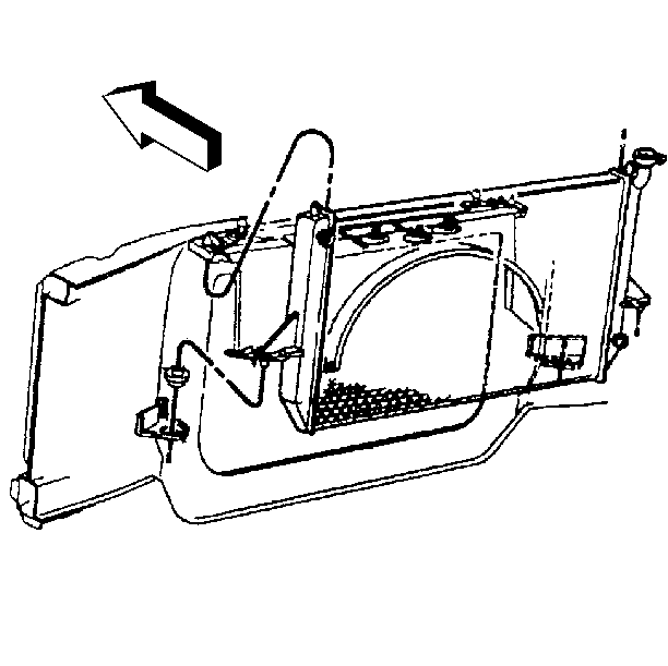
- Disconnect the battery
negative cable. Refer to
Battery Replacement
in Engine Electrical.
- Remove the engine cover. Refer to
Engine Cover Replacement
in Interior Trim.
- Remove the air cleaner assembly. Refer to
Air Cleaner Assembly Replacement
in Engine Controls.
- Remove the air cleaner outlet duct from the throttle body. Refer
to
Air Cleaner Outlet Duct Replacement
in Engine Controls.
- Remove the radiator. Refer to
Radiator Replacement
in Engine Cooling.
- Disconnect the air conditioning pipes at the accumulator and the
condenser, if equipped. Refer to
Auxiliary Air Conditioning Compressor and Condenser Hose Replacement
in HVAC Systems with A/C - Manual.
Caution: In order to avoid possible injury or vehicle damage, always replace
the accelerator control cable with a NEW cable whenever you remove the engine
from the vehicle.
In order to avoid cruise control cable damage, position the cable out
of the way while you remove or install the engine. Do not pry
or lean against the cruise control cable and do not kink the cable. You must
replace a damaged cable.
- Remove the accelerator control cable from the throttle shaft. Refer
to
Accelerator Control Cable Replacement
in Engine Controls.
- Remove the cruise control cable, if equipped from the throttle
shaft. Refer to
Cruise Control Cable Replacement
in Cruise Control.
- Remove the accelerator control cable and the cruise control cable
from the accelerator control cable bracket.
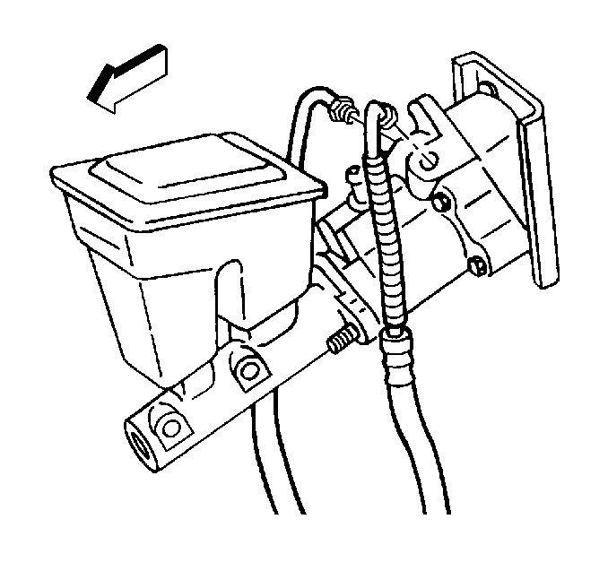
- Remove the power steering
reservoir and drain the fluid. Refer to
Remote Power Steering Fluid Reservoir Replacement
in Power Steering
Systems.
- Disconnect the pipes from the hydro boost unit. Refer to
Power Brake Booster Replacement
in Hydraulic
Brakes.
- Disconnect the master cylinder from the hydro boost unit. Refer
to
Master Cylinder Replacement
in Hydraulic Brakes.
- Tie the master cylinder to the oil fill tube.
- Disconnect the steering shaft from the steering gear. Refer to Intermediate Steering Shaft Replacement
in Steering Wheel
and Column.
- Disconnect the heater hoses from the engine. Refer to
Heater Water Bypass Valve Replacement
in Heating
and Ventilation (Non-A/C).
- Disconnect the vacuum hose from the water control valve.
- Disconnect the wire connector from the water control valve.
- Disconnect the fuse box and the wiring harness from the bulkhead
connector. Refer to
Bulkhead/Underhood Fuse-Relay Center Wiring (Electrical)
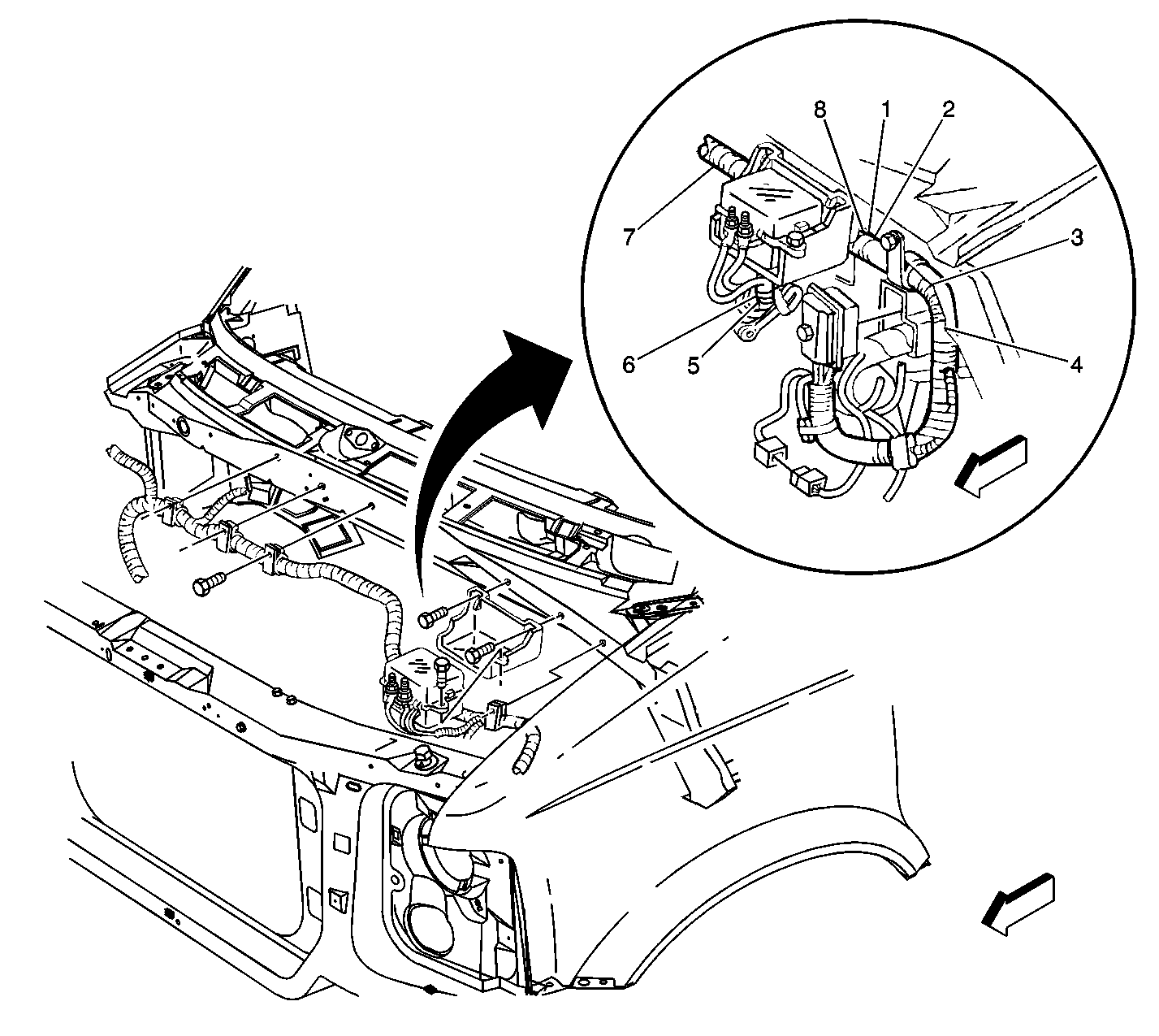
in Wiring Systems.
- Disconnect all related electrical connectors that connect the
wiring harness to the body under the hood including the following: Refer to
Engine/Center of Front of Dash Wiring (Electrical)
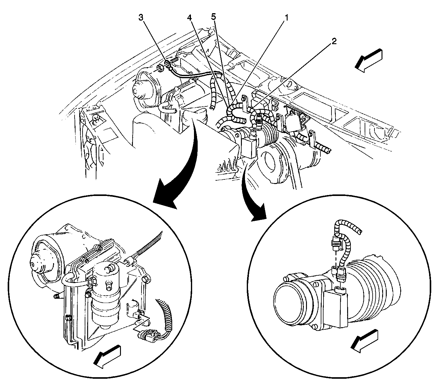
in Wiring Systems.
| • | The cruise control module |
- Remove the wiring harness from the retainers and lay the harness
on the engine.
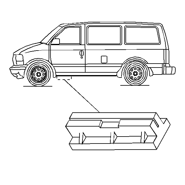
- Remove the front section
of the running boards, if equipped. Refer to
Assist Step Front Extension Replacement
in Frame and Underbody.
- Install the J 41602
to the pinch weld area on both sides of the vehicle.
- Position the front hoist arms under the J 41602
. Refer to
Lifting and Jacking the Vehicle
in General Information for proper position of the rear
hoist arms.
- Make sure the rear of the vehicle is slightly higher than the
front.
- Raise the vehicle.
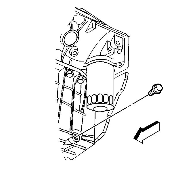
- Remove the oil pan drain
plug and drain the engine oil into a suitable container.
- Remove the rear propeller shaft. Refer to
Rear Propeller Shaft Replacement
in Propeller Shaft.
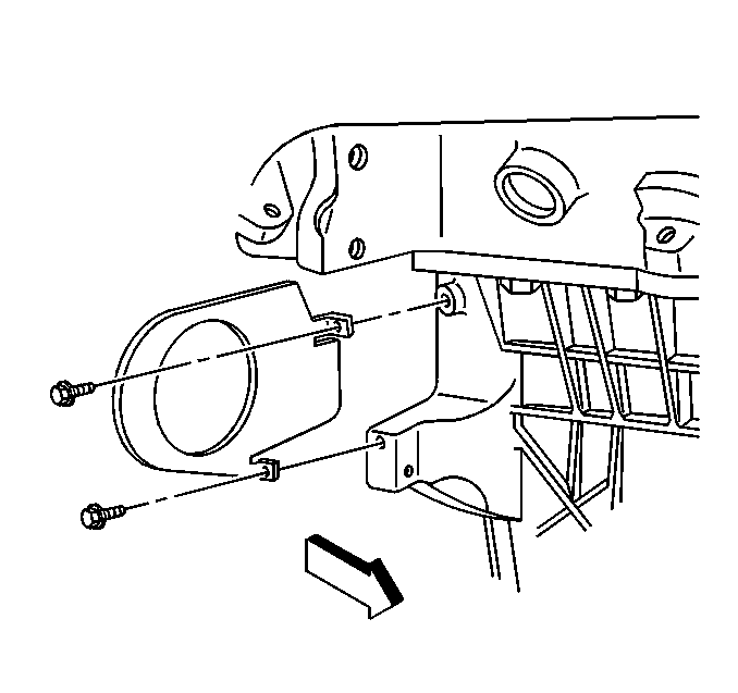
- Remove the starter. Refer
to
Starter Motor Replacement
in Engine Electrical.
- Remove the transmission cover.
- Remove the torque converter bolts through the starter opening.
- Disconnect the shift cable from the transmission. Refer to
Shift Cable Replacement
in Automatic Transmission
- 4L60-E.
- Disconnect the wire connector from the wiring harness above the
transmission.
- Disconnect the exhaust system at the main flange behind the catalytic
converter. Refer to
Catalytic Converter Replacement
in Engine Exhaust.
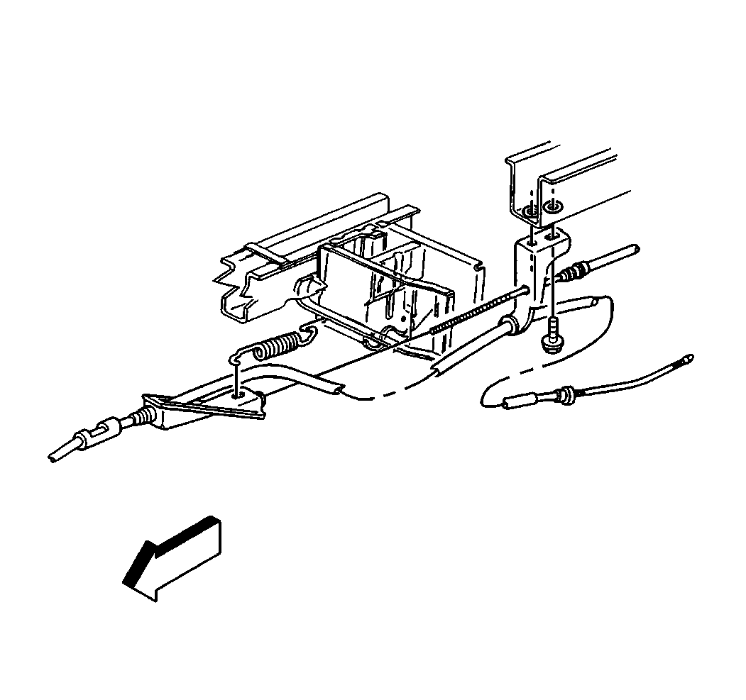
- Remove the park brake
bracket from the frame.
- Disconnect the rear brake pipe from the brake pressure modulator
valve (BPMV). Refer to
Brake Pressure Modulator Valve Replacement
in Anti Lock Brakes.
- Remove the front bumper. Refer to
Front Bumper Replacement
in Bumper and Facias.
- Disconnect the power steering cooler from the front air deflector.
Refer to
Power Steering Cooler Pipe/Hose Replacement
in Power Steering Systems.
- Disconnect the inflatable restraint front end discriminating sensor
electrical connector. Refer to
Inflatable Restraint Front End Discriminating Sensor Replacement
in SIR.
- Disconnect the fender wheelhouse extensions from the chassis to
the frame. Refer to
Wheelhouse Extension Replacement
in Body Front End.
- Disconnect the rear air conditioning pipes at the rear crossmember,
if equipped.
Leave the air conditioning pipes attached to the powertrain assembly.
| • | Refer to Accumulator Tube Replacement - Auxiliary
Side
in HVAC Systems with A/C - Manual. |
| • | Refer to Evaporator Tube Replacement - Auxiliary
Side
in HVAC Systems with A/C - Manual. |
- Disconnect the fuel pipes at the fuel filter. Refer to
Fuel Hose/Pipes Assembly Replacement
in Engine
Controls.
- Pull the fuel pipes through the crossmember (forward). Lay the
fuel pipes on the transmission.
- Disconnect the fuel tank electrical connector. Refer to
Undercarriage
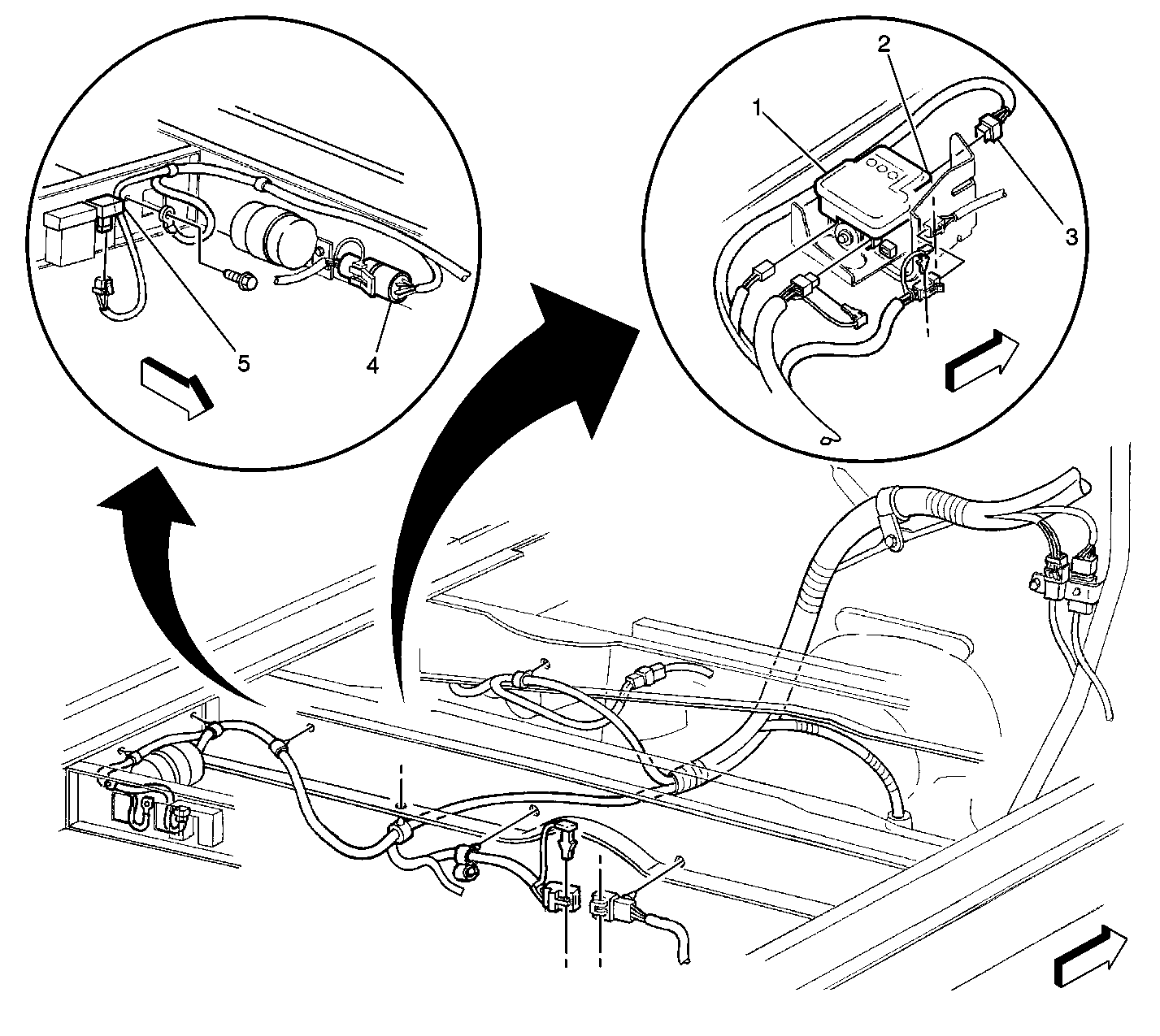
- Disconnect the EVAP vent valve electrical connector.
- Remove the bolt and the ground wire at the chassis by the EVAP
vent valve.
- Make sure all the connections are disconnected between the chassis
and the frame.
- Disconnect the transfer case vent hose, if equipped.
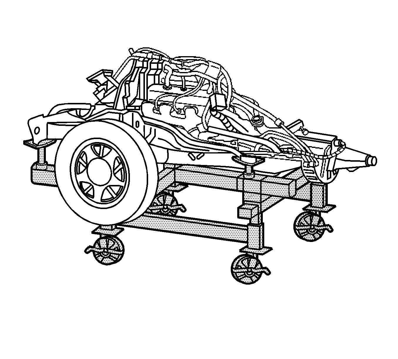
- Position the J 39580
under the frame assembly.
- Lower the vehicle.
- Adjust J 39580
to
properly support the frame assembly with the engine, transmission, front suspension
components, and front differential carrier assembly, if equipped.
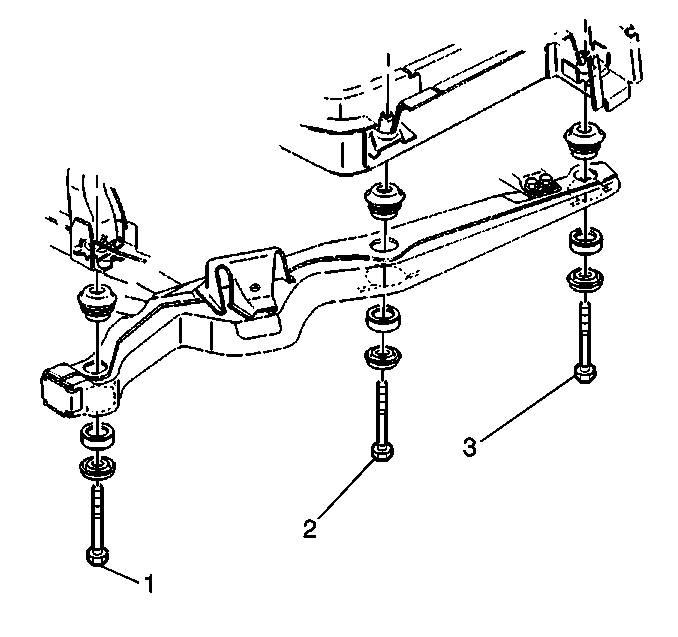
- Remove the body mount
bolts (1), (2) and (3). Refer to
Body Mount Replacement
in Frame and Underbody.
- Place a jack stand under the transmission crossmember to prevent
the frame assembly from tipping off of the J 39580
.
- Raise the hoist in order to separate the body from the frame assembly.
- Install support stands under the rear axle.
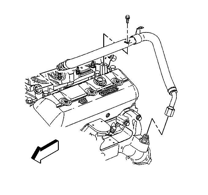
- Remove the EGR valve inlet
pipe from the intake manifold and the exhaust manifold.
- Disconnect the spark plug wires from the spark plugs. Refer to
Spark Plug Wire Harness Replacement
in Engine
Electrical.
- Remove the distributor cap with the spark plug wire harness.
- Remove the air conditioning compressor and the power steering
pump mounting bracket. Refer to
Accessory Mounting Brackets Replacement
.
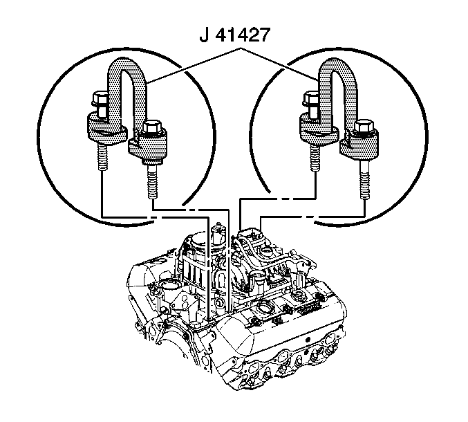
- Install the J 41427
using the following procedure:
| 59.1. | Remove the two right rear lower intake manifold bolts. |
| 59.2. | Install the J 41427
marked RIGHT REAR. |
Notice: Use the correct fastener in the correct location. Replacement fasteners
must be the correct part number for that application. Fasteners requiring
replacement or fasteners requiring the use of thread locking compound or sealant
are identified in the service procedure. Do not use paints, lubricants, or
corrosion inhibitors on fasteners or fastener joint surfaces unless specified.
These coatings affect fastener torque and joint clamping force and may damage
the fastener. Use the correct tightening sequence and specifications when
installing fasteners in order to avoid damage to parts and systems.
| 59.3. | Install the retaining
bolts. |
Tighten
Tighten the retaining bolts to 15 N·m (11 lb ft).
| 59.4. | Remove the two left front lower intake manifold bolts. |
| 59.5. | Install the J 41427
marked LEFT FRONT with the arrow pointing to the front of the engine. |
| 59.6. | Install the retaining bolts |
Tighten
Tighten the retaining bolts to 15 N·m (11 lb ft).
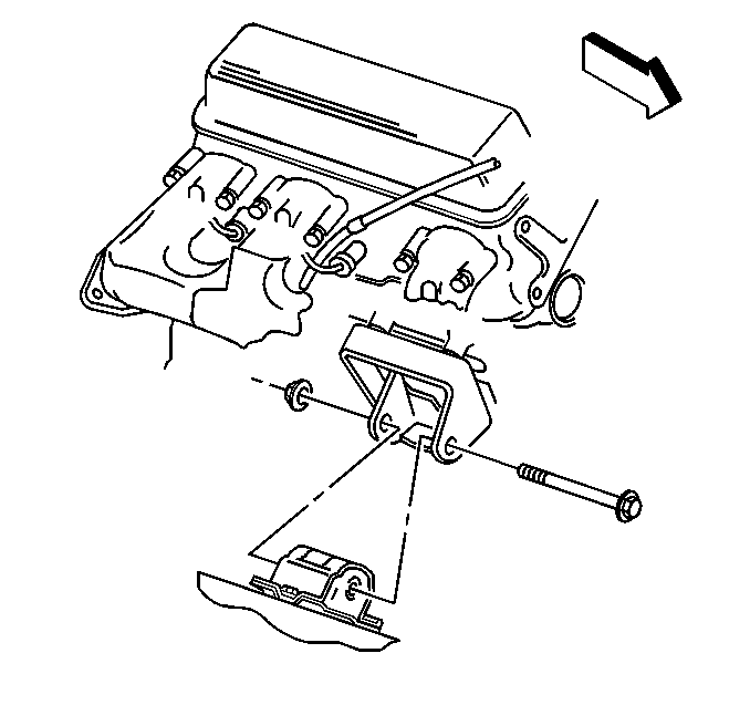
- Remove the engine mount
through bolts.
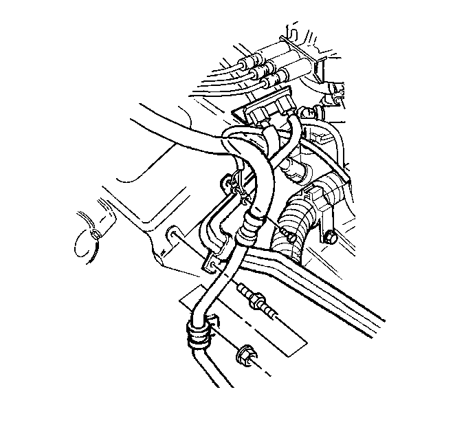
- Remove the bolt holding
the fuel pipe bracket to the rear of the left cylinder head.
- Disconnect the fuel pipes at the rear of the engine. Refer to
Fuel Hose/Pipes Replacement - Engine Compartment
in Engine Controls.
- Disconnect the electrical harness at the transmission.
- Disconnect all the wire harness connections and the ground wires
from the engine and move the harness aside.
| • | Refer to
Engine Wiring, RH Side
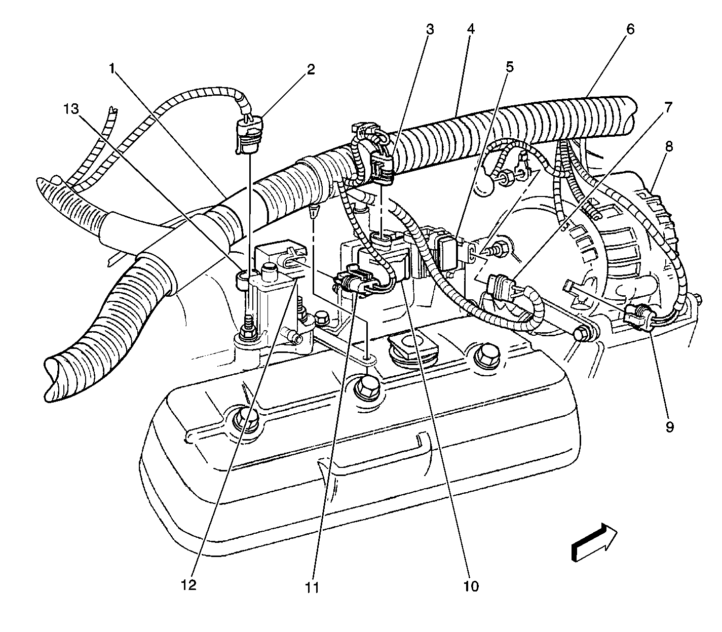
|
| • | Refer to
Engine Wiring, LH Side (Electrical)
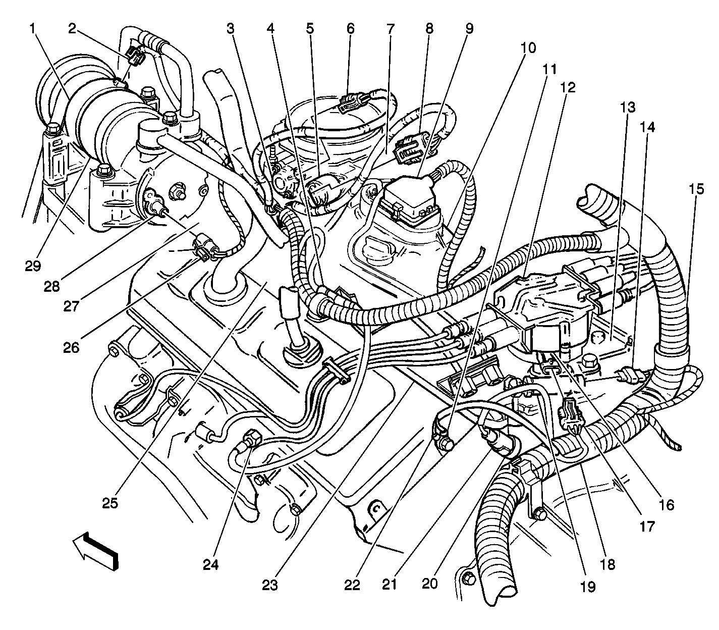
|
- Remove the transfer case to engine block brace, if equipped.
Refer to
Transfer Case Replacement
in Transfer Case.
- Raise the engine slightly. Support the front of the transmission
with suitable floor stand and a block of wood. Do not support the transmission
under the oil pan.
- Remove the exhaust pipe from the exhaust manifolds. Refer to
Catalytic Converter Replacement
in Engine Exhaust.
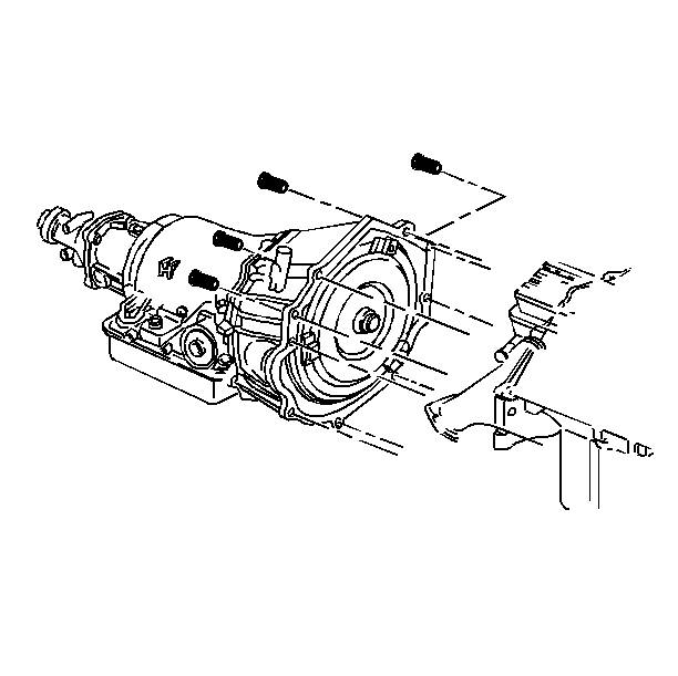
- Remove the transmission
to engine bolts.
- Disconnect the engine from the transmission.
- Remove the engine from the frame.
Installation Procedure
Important: If you install a new engine, make sure any remaining components, brackets,
or accessories are transferred to the new engine.
- Install the engine into the frame.
- Connect the engine to the transmission. Refer to
Transmission Replacement
in Automatic Transmission - 4L60-E.
- Remove the support from under the transmission.
- Lower the engine and the transmission onto the engine mounts.

- Install the engine mount
through-bolts.
Tighten
Tighten the engine mount through-bolts to 68 N·m (50 lb ft).

- Remove the J 41427
from the engine.
- Apply thread lock GM PN 12345382 or equivalent to
the threads of the lower intake manifold bolts.
- Install the intake manifold bolts.
Tighten
- Tighten the bolts the first pass to 3 N·m (27 lb in).
- Tighten the bolts the second pass to 12 N·m (106 lb in).
- Tighten the bolts the first pass to 15 N·m (11 lb ft).
- Install the exhaust pipe to the exhaust manifolds. Refer to
Catalytic Converter Replacement
in Engine Exhaust.
- Connect the fuel pipes at the rear of the engine. Refer to
Fuel Hose/Pipes Replacement - Engine Compartment
in Engine Controls.

- Connect the fuel pipe
bracket to the rear of the left cylinder head.
Tighten
Tighten the fuel pipe bracket bolt to 30 N·m (22 lb ft).
- Connect all of the wiring harness connections and the ground wires
to the engine.
| • | Refer to
Engine Wiring, RH Side

|
| • | Refer to
Engine Wiring, LH Side (Electrical)

|
- Connect the electrical harness at the transmission.
- Install the transfer case to engine block brace, if equipped.
Refer to
Transfer Case Replacement
in Transfer Case.

- Install the EGR valve
inlet pipe to the intake manifold and the exhaust manifold.
Tighten
| • | Tighten the EGR valve inlet pipe intake manifold nut to 25 N·m
(18 lb ft). |
| • | Tighten the EGR valve inlet pipe exhaust manifold nut to 30 N·m
(22 lb ft). |
| • | Tighten the EGR valve inlet pipe clamp bolt to 25 N·m
(18 lb ft). |
- Install the air conditioning compressor, if equipped, and the
power steering pump mounting bracket. Refer to
Accessory Mounting Brackets Replacement
.
- Install the distributor cap. Refer to
Distributor Replacement
in Engine Electrical.
- Install the spark plug wires. Refer to
Spark Plug Wire Harness Replacement
in Engine Electrical.

Important: Align the frame using the two alignment holes in the frame and the body.
Use a pry bar or dowel pin in order to align the holes as the vehicle is being
lowered/raised into the frame.
- Lower the vehicle onto the engine/frame assembly.

Important: The six body bolts (frame to body) must be tightened in sequence in
order to ensure proper alignment of the frame to the chassis.
- Install the body bolts (frame to body) (1), (2), and (3).
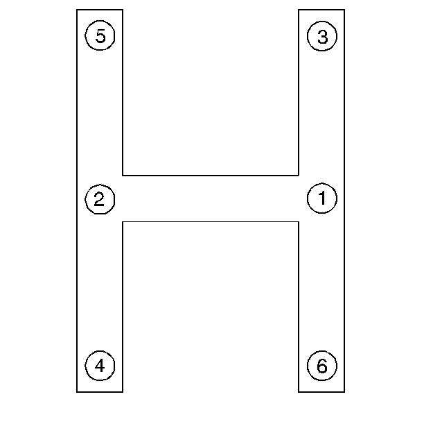
- Tighten the body bolts
using the following sequence.
Tighten
- Tighten all of the body bolts in the sequence shown to 35 N·m
(26 lb ft).
- Tighten the right center body bolt first to 155 N·m
(114 lb ft).
- Tighten the left center body bolt second to 155 N·m
(114 lb ft).
- Tighten the right front body bolt third to 90N·m (66 lb ft).
- Tighten the left rear body bolt fourth to 90 N·m
(66 lb ft).
- Tighten the left front body bolt fifth to 90 N·m
(66 lb ft).
- Tighten the right rear body bolt last to 90 N·m (66 lb ft).
- Raise the vehicle.

- Install the transfer case
vent tube, if equipped.
- Connect the wire connector to the wiring harness above the transmission.
- Connect the shift cable to the transmission. Refer to
Shift Cable Replacement
in Automatic Transmission
- 4L60-E.
- Install the torque converter bolts. Refer to
Flywheel to Torque Converter Bolt Replacement
in Automatic Transmission -
4L60-E.
- Install the transmission cover.
Tighten
Tighten the transmission cover bolts to 12 N·m (106 lb in).
- Install the starter. Refer to
Starter Motor Replacement
in Engine Electrical.
- Install the rear propeller shaft. Refer to
Rear Propeller Shaft Replacement
in Propeller Shaft.
- Connect the power steering cooler. Refer to
Power Steering Cooler Pipe/Hose Replacement
in Power Steering
Systems.
- Connect the inflatable restraint front end discriminating sensor
electrical connector. Refer to
Inflatable Restraint Front End Discriminating Sensor Replacement
in SIR.
- Connect the fender wheelhouse extensions from chassis to the frame.
Refer to
Wheelhouse Extension Replacement
in Body Front End.
- Install the front bumper. Refer to
Front Bumper Replacement
in Bumper and Facias.
- Install the catalytic converter assembly to the exhaust system.
Refer to
Catalytic Converter Replacement
in Engine Exhaust.
- Connect the fuel pipes at the fuel filter. Refer to
Fuel Hose/Pipes Assembly Replacement
in Engine
Controls.
- Connect the fuel tank electrical connector. Refer to
Undercarriage

- Connect the EVAP vent valve electrical connector.
- Install the bolt and the ground wire at the chassis by the EVAP
vent valve.
- Ensure that all of the electrical connections are connected between
the chassis and the frame.

- Install the bolt and the
park brake bracket to the frame.
Tighten
Tighten the park brake bracket bolt to 24 N·m (17 lb in).
- Connect the rear air conditioning pipes at the rear crossmember,
if equipped.
| • | Refer to Accumulator Tube Replacement - Auxiliary
Side
in HVAC Systems with A/C - Manual. |
| • | Refer to Evaporator Tube Replacement - Auxiliary
Side
in HVAC Systems with A/C - Manual. |
- Connect the rear brake pipe to the BPMV. Refer to
Brake Pressure Modulator Valve Replacement
in Anti Lock Brakes.
- Lower the vehicle.

- Remove both of the J 41602
.
- Install the front section of the running boards. Refer to
Assist Step Front Extension Replacement
in Frame
and Underbody.
- Install the wiring harness in the retainers.
- Connect the fuse box and the wiring harness to the bulkhead connector.
Refer to
Bulkhead/Underhood Fuse-Relay Center Wiring (Electrical)

in Wiring Systems.
- Connect all related connectors including: Refer to
Engine/Center of Front of Dash Wiring (Electrical)

in Wiring Systems.
| • | The cruise control module |
- Connect the steering shaft to the steering gear. Refer to Intermediate Steering Shaft Replacement
in Steering Wheel
and Columns.
- Connect the heater hoses to the engine. Refer to
Heater Water Bypass Valve Replacement
in Heating and Ventilation
- (Non A/C)
- Connect the wire connector to the water control valve.
- Connect the vacuum hose to the water control valve.

- Connect the pipes to the
hydro boost. Refer to
Power Brake Booster Replacement
in Hydraulic Brakes.
- Install the power steering reservoir. Refer to
Remote Power Steering Fluid Reservoir Replacement
in Power Steering
Systems.
- Install the master cylinder to the hydro boost. Refer to
Master Cylinder Replacement
in Hydraulic Brakes.
Caution: In order to avoid possible injury or vehicle damage, always replace
the accelerator control cable with a NEW cable whenever you remove the engine
from the vehicle.
In order to avoid cruise control cable damage, position the cable out
of the way while you remove or install the engine. Do not pry
or lean against the cruise control cable and do not kink the cable. You must
replace a damaged cable.
- Install the NEW accelerator control cable. Refer to
Accelerator Control Cable Replacement
in Engine Controls.
- Install the cruise control cable in the throttle body bracket.
- Connect the cruise control cable to the throttle shaft. Refer
to
Cruise Control Cable Replacement
in Cruise Controls.
- Connect the air conditioning pipes at the accumulator and the
condenser, if equipped. Refer to
Auxiliary Air Conditioning Compressor and Condenser Hose Replacement
in HVAC Systems with A/C - Manual.
- Install the radiator. Refer to
Radiator Replacement
in Engine Cooling.
- Fill the cooling system with the proper grade of engine coolant.
Refer to
Cooling System Draining and Filling
in Engine Cooling.
- Install the air cleaner outlet duct to the throttle body. Refer
to
Air Cleaner Outlet Duct Replacement
in Engine Controls.
- Install the air cleaner assembly. Refer to
Air Cleaner Assembly Replacement
in Engine Controls.
- Fill the crankcase with the proper grade of engine oil. Refer
to
Engine Oil and Oil Filter Replacement
- Fill and bleed the brake system. Refer to
Hydraulic Brake System Bleeding
in Hydraulic Brakes.
- Fill the transmission with the proper grade and quantity of transmission
fluid. Refer to
Transmission Replacement
in Automatic Transmission - 4L60-E.
- Fill the power steering system with the proper grade and quantity
of power steering fluid. Refer to
Checking and Adding Power Steering Fluid
in Power Steering Systems.
- Connect the battery negative cable. Refer to
Battery Replacement
in Engine Electrical.
- Recharge the air conditioning system and check for proper operation,
if equipped. Refer to
Refrigerant System Checks
in HVAC Systems with A/C - Manual.
- Install the engine cover. Refer to
Engine Cover Replacement
in Interior Trim.
- Operate the engine and check for proper operation. Refer to Engine Set-Up and Testing
.


