Rear Rail Replacement SWB
Removal Procedure
- Disable the SIR system. Refer to SIR Disabling and Enabling in SIR.
- Remove the rear compartment floor carpet. Refer to Rear Compartment Floor Panel Carpet Replacement in Interior Trim
- Disconnect the negative battery cable. Refer to Battery Negative Cable Disconnection and Connection .
- Remove the battery. Refer to Battery Replacement .
- Remove the battery tray. Refer to Battery Tray Replacement .
- Remove the spare wheel carrier. Refer to Spare Wheel Carrier Replacement .
- Raise and support the vehicle. Refer to Lifting and Jacking the Vehicle .
- Remove the rear wheels. Refer to Tire and Wheel Removal and Installation .
- Remove the rear wheel liners. Refer to Rear Inner Wheelhouse Replacement in Body Rear End.
- Remove the rear bumper fascia. Refer to Rear Bumper Fascia Replacement .
- Remove the rear muffler assembly. Refer to Exhaust Muffler Replacement - Left Side and Exhaust Muffler Replacement - Right Side .
- Remove the rear muffler heat shields. Refer to Exhaust Muffler Heat Shield Replacement - Left Side and Exhaust Muffler Heat Shield Replacement - Right Side .
- Remove the rear muffler hanger bracket. Refer to Exhaust Hanger Mounting Bracket Replacement .
- Remove the rear frame. Refer to Rear Frame Replacement .
- Remove and note the location of any sound deadening materials.
- Remove and note the location of the sealers and anti-corrosion materials from the repair area, as necessary. Refer to Anti-Corrosion Treatment and Repair .
- Remove the rear end panel. Refer to Rear End Panel Replacement .
- Remove the side extension panel assembly. Refer to Body Side Inner Panel Extension Replacement .
- Repair as much of the damage as possible.
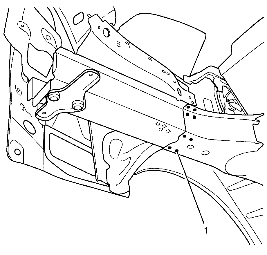
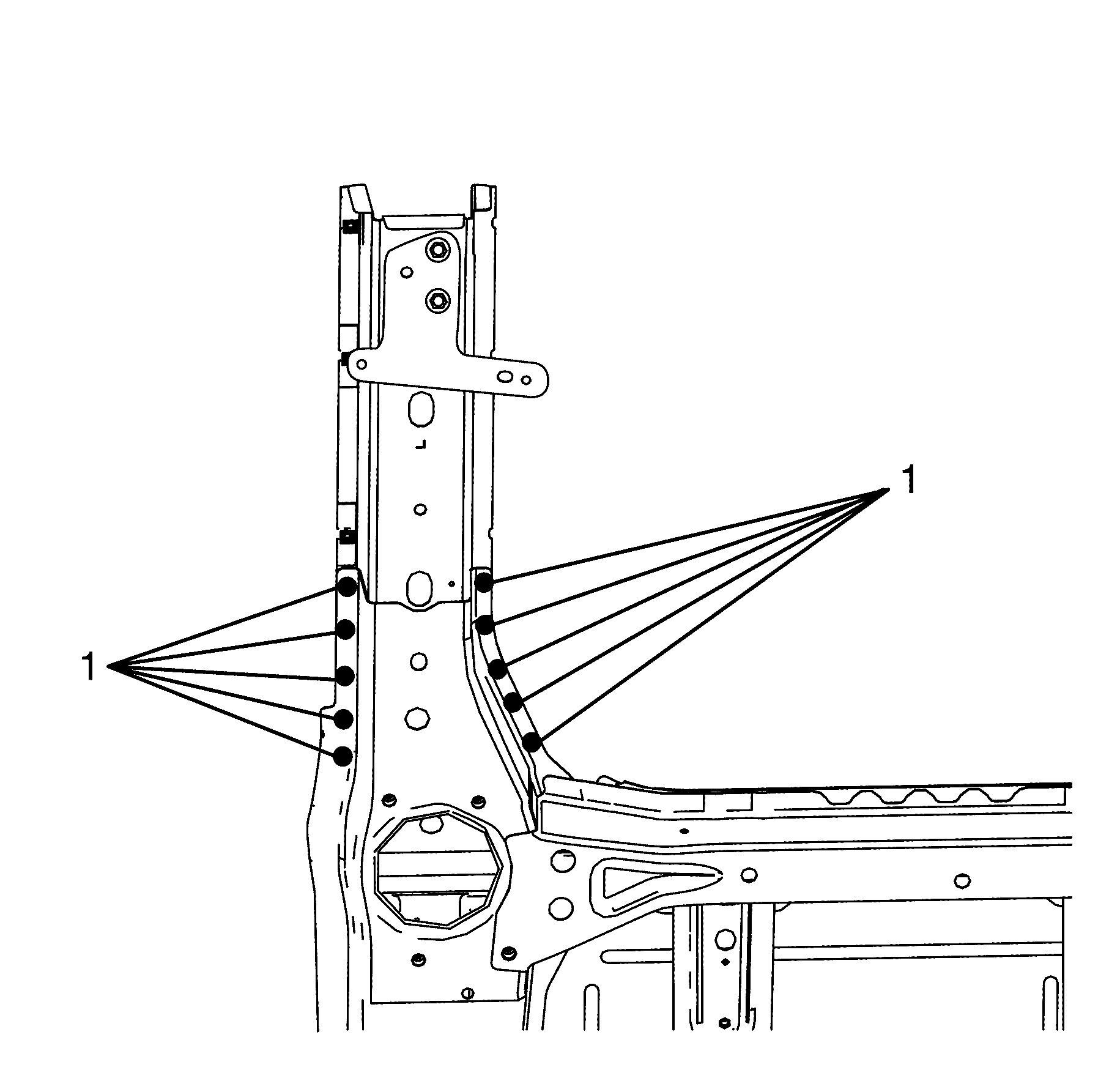
- Locate, mark and drill out all factory welds (1).
- Remove the damaged rail section from the vehicle.
Caution: Refer to Approved Equipment for Collision Repair Caution in the Preface section.
Caution: Refer to Foam Sound Deadeners Caution in the Preface section.
Caution: Refer to Vehicle Lifting Caution in the Preface section.
Important: This procedure should be used if the damage is rearward of the factory joint in the rail assembly.
Important: Do not damage any inner panels or reinforcements.
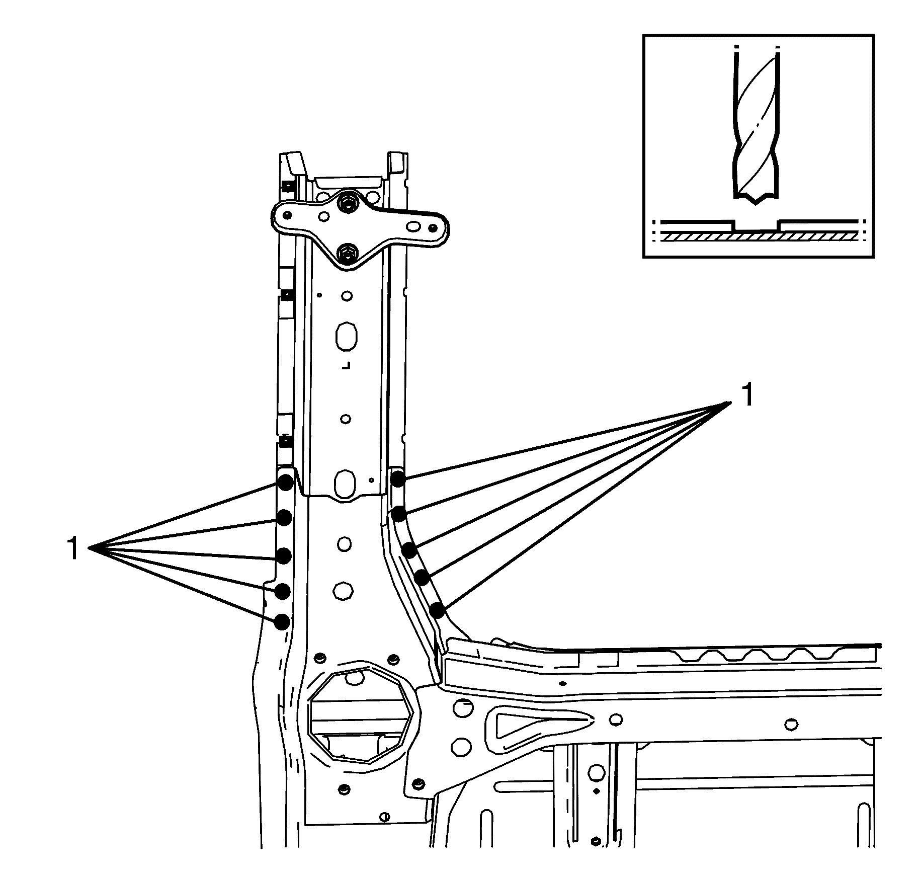
Important: Note the number and location of welds for installation of the service assembly.
Installation Procedure
- Drill 8 mm (5/16 in ) puddle weld holes in the service part, as necessary, in the locations puddle welding is needed.
- Prepare the mating surfaces, as necessary.
- Apply structural adhesive GM6449G or equivalent to all mating surfaces.
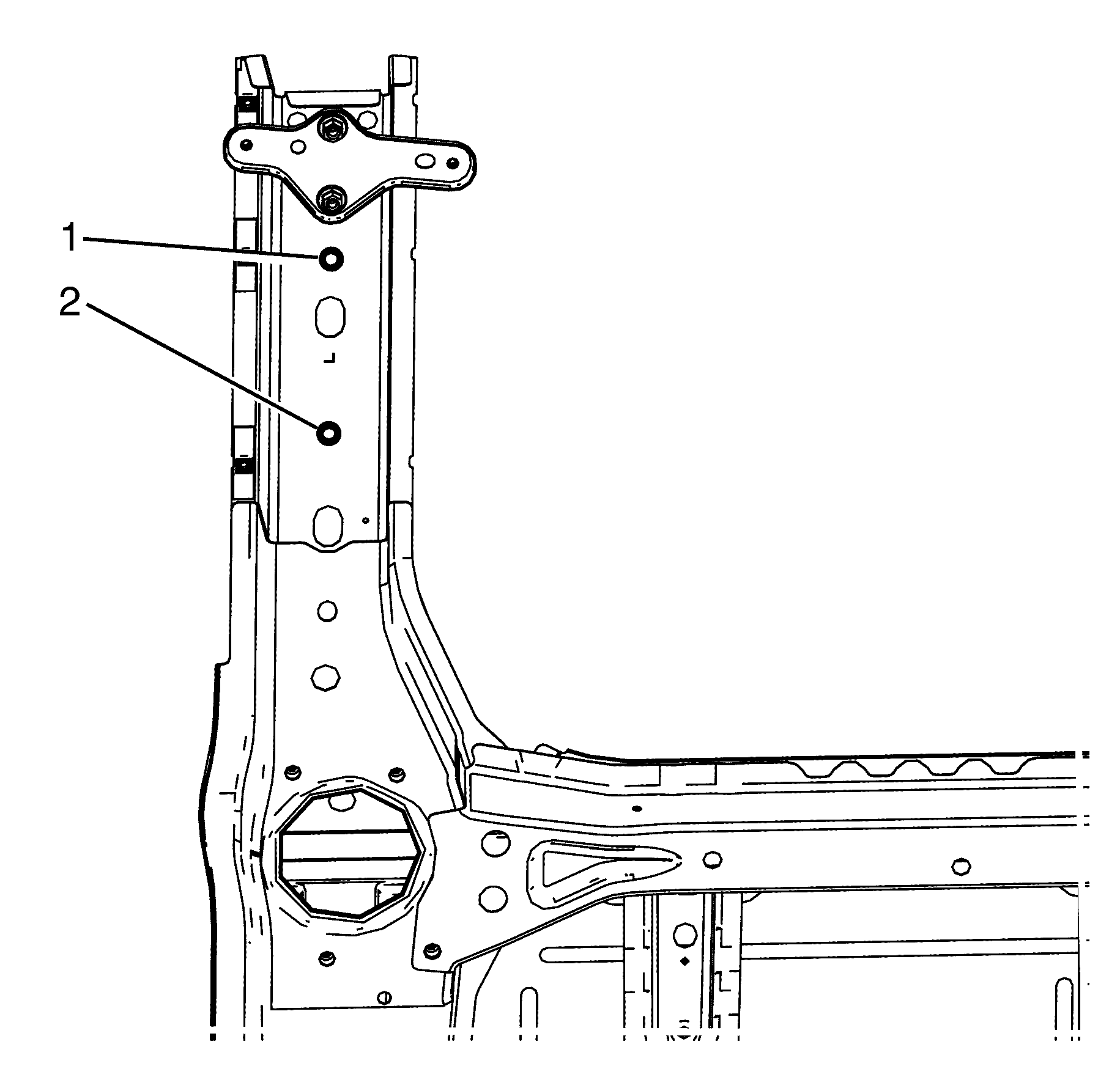
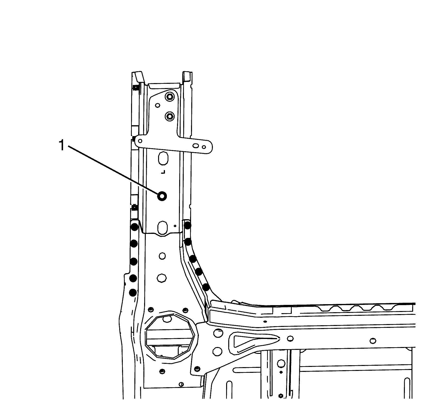
- Align the rear rail extension using the datum points (1) and (2) to the vehicle.
- Weld (1) the rear rail extension to the vehicle.
- Clean and prepare all welded surfaces.
- Install the rear end panel. Refer to Rear End Panel Replacement .
- Install the side extension panel assembly. Refer to Body Side Inner Panel Extension Replacement .
- Apply the sealers, and anti-corrosion materials to the repair area, as necessary. Refer to Anti-Corrosion Treatment and Repair .
- Paint the repaired area. Refer to Basecoat/Clearcoat Paint Systems .
- Install the rear frame. Refer to Rear Frame Replacement .
- Install the rear muffler hanger bracket. Refer to Exhaust Hanger Mounting Bracket Replacement .
- Install the rear muffler heat shields. Refer to Exhaust Muffler Heat Shield Replacement - Left Side or Exhaust Muffler Heat Shield Replacement - Right Side .
- Install the rear muffler assembly. Refer to Exhaust Muffler Replacement - Left Side or Exhaust Muffler Replacement - Right Side .
- Install the rear bumper fiasco. Refer to Rear Bumper Fascia Replacement .
- Install the rear wheel liners. Refer to Rear Inner Wheelhouse Replacement in Body Rear End.
- Install the spare wheel carrier. Refer to Spare Wheel Carrier Replacement .
- Install the rear wheels. Refer to Tire and Wheel Removal and Installation .
- Lower the vehicle.
- Install the battery tray. Refer to Battery Tray Replacement .
- Install the battery. Refer to Battery Replacement .
- Connect the negative battery cable. Refer to Battery Negative Cable Disconnection and Connection .
- Install the rear compartment floor carpet. Refer to Rear Compartment Floor Panel Carpet Replacement in Interior Trim.
- Enable the SIR system. Refer to SIR Disabling and Enabling in SIR.
- If re-programming is required. Refer to Control Module References .
Important: This part has structural weld-thru adhesive in the joint areas. Replace this with additional spot welds at the attachment points. This can be accomplished by adding an additional weld between each factory weld in all areas.
Important: If the location of the original spot weld holes can not be determined, or if structural weld-thru adhesive is present, space the puddle weld holes every 32 mm (1¼ in).
Important: Spot welding is the preferred method for attaching panels and should be used wherever possible. A puddle weld should be performed where your spot welder is unable to reach.

Rear Rail Replacement LWB
Removal Procedure
- Disable the SIR system. Refer to SIR Disabling and Enabling in SIR.
- Remove the rear compartment floor carpet. Refer to Rear Compartment Floor Panel Carpet Replacement in Interior Trim
- Disconnect the negative battery cable. Refer to Battery Negative Cable Disconnection and Connection .
- Remove the battery. Refer to Battery Replacement .
- Remove the battery tray. Refer to Battery Tray Replacement .
- Remove the spare wheel carrier. Refer to Spare Wheel Carrier Replacement .
- Raise and support the vehicle. Refer to Lifting and Jacking the Vehicle .
- Remove the rear wheels. Refer to Tire and Wheel Removal and Installation .
- Remove the rear wheel liners. Refer to Rear Inner Wheelhouse Replacement in Body Rear End.
- Remove the rear bumper fiasco. Refer to Rear Bumper Fascia Replacement .
- Remove the rear muffler assembly. Refer to Exhaust Muffler Replacement - Left Side and Exhaust Muffler Replacement - Right Side .
- Remove the rear muffler heat shields. Refer to Exhaust Muffler Heat Shield Replacement - Left Side and Exhaust Muffler Heat Shield Replacement - Right Side .
- Remove the rear muffler hanger bracket. Refer to Exhaust Hanger Mounting Bracket Replacement .
- Remove the rear frame. Refer to Rear Frame Replacement .
- Remove and note the location of any sound deadening materials.
- Remove and note the location of the sealers and anti-corrosion materials from the repair area, as necessary. Refer to Anti-Corrosion Treatment and Repair .
- Remove the rear end panel. Refer to Rear End Panel Replacement .
- Remove the side extension panel assembly. Refer to Body Side Inner Panel Extension Replacement
- Repair as much of the damage as possible.
- Locate, mark and drill out all factory welds (1).
- Remove the damaged rail section from the vehicle.
Caution: Refer to Approved Equipment for Collision Repair Caution in the Preface section.
Caution: Refer to Foam Sound Deadeners Caution in the Preface section.
Caution: Refer to Vehicle Lifting Caution in the Preface section.
Important: This procedure should be used if the damage is rearward of the factory joint in the rail assembly.

Important: Do not damage any inner panels or reinforcements.
Important: Note the number and location of welds for installation of the service assembly.
Installation Procedure
- Drill 8 mm (5/16 in ) puddle weld holes in the service part, as necessary, in the locations puddle welding is needed.
- Prepare the mating surfaces, as necessary.
- Apply structural adhesive GM6449G or equivalent to all mating surfaces.
- Align the rear rail extension using the datum points (1) and (2) to the vehicle.
- Weld (1) the rear rail extension to the vehicle.
- Clean and prepare all welded surfaces.
- Install the rear end panel. Refer to Rear End Panel Replacement .
- Install the side extension panel assembly. Refer to Body Side Inner Panel Extension Replacement .
- Apply the sealers, and anti-corrosion materials to the repair area, as necessary. Refer to Anti-Corrosion Treatment and Repair .
- Paint the repaired area. Refer to Basecoat/Clearcoat Paint Systems .
- Install the rear frame. Refer to Rear Frame Replacement .
- Install the rear muffler hanger bracket. Refer to Exhaust Hanger Mounting Bracket Replacement .
- Install the rear muffler heat shields. Refer to Exhaust Muffler Heat Shield Replacement - Left Side or Exhaust Muffler Heat Shield Replacement - Right Side .
- Install the rear muffler assembly. Refer to Exhaust Muffler Replacement - Left Side or Exhaust Muffler Replacement - Right Side .
- Install the rear bumper fiasco. Refer to Rear Bumper Fascia Replacement .
- Install the rear wheel liners. Refer to Rear Inner Wheelhouse Replacement in Body Rear End.
- Install the spare wheel carrier. Refer to Spare Wheel Carrier Replacement .
- Install the rear wheels. Refer to Tire and Wheel Removal and Installation .
- Lower the vehicle.
- Install the battery tray. Refer to Battery Tray Replacement .
- Install the battery. Refer to Battery Replacement .
- Connect the negative battery cable. Refer to Battery Negative Cable Disconnection and Connection .
- Install the rear compartment floor carpet. Refer to Rear Compartment Floor Panel Carpet Replacement in Interior Trim.
- Enable the SIR system. Refer to SIR Disabling and Enabling in SIR.
Important: This part has structural weld-thru adhesive in the joint areas. Replace this with additional spot welds at the attachment points. This can be accomplished by adding an additional weld between each factory weld in all areas.
Important: If the location of the original spot weld holes can not be determined, or if structural weld-thru adhesive is present, space the puddle weld holes every 32 mm (1¼ in).
Important: Spot welding is the preferred method for attaching panels and should be used wherever possible. A puddle weld should be performed where your spot welder is unable to reach.
Rear Rail Replacement Sportwagon
Removal Procedure
- Disable the SIR system. Refer to SIR Disabling and Enabling.
- Disconnect the negative battery cable. Refer to Battery Negative Cable Disconnection and Connection.
- Remove the rear bumper fascia. Refer to Rear Bumper Fascia Replacement.
- Remove the rear bumper impact bar. Refer to Rear Bumper Impact Bar Replacement.
- Remove the rear end trim finish panel. Refer to Rear End Trim Finish Panel Replacement.
- Remove the rear compartment floor panel carpet. Refer to Rear Compartment Floor Panel Carpet Replacement.
- Remove the load floor stationary panel carpet. Refer to Load Floor Stationary Panel Carpet Replacement.
- Remove the liftgate weatherstrip. Refer to Liftgate Weatherstrip Replacement.
- Remove the quarter inner trim finish panel. Refer to Quarter Inner Trim Finish Panel Replacement.
- Remove the battery. Refer to Battery Replacement.
- Remove the battery tray. Refer to Battery Tray Replacement.
- Remove the pressure relief valve. Refer to Pressure Relief Valve Replacement.
- Remove the tail lights. Refer to Tail Lamp Assembly and /or Backup, Sidemarker, Stop, Turn Signal Bulb Replacement.
- Remove the liftgate. Refer to Liftgate Replacement.
- Remove the rear muffler assembly. Refer to Exhaust Muffler Replacement - Left Side or Exhaust Muffler Replacement - Right Side.
- Remove the rear muffler heat shields. Refer to Exhaust Muffler Heat Shield Replacement - Left Side or Exhaust Muffler Heat Shield Replacement - Right Side.
- Remove the rear bumper bracket. Refer to Rear Bumper Bracket Replacement.
- Remove the rear muffler hanger bracket. Refer to Exhaust Hanger Mounting Bracket Replacement.
- Remove the rear frame. Refer to Rear Frame Replacement.
- Remove and note the location of any sound deadening materials.
- Remove the spare wheel and emergency kit from the rear compartment.
- Remove the spare wheel carrier. Refer to Spare Wheel Carrier Replacement.
- Remove and note the location of the sealers and anti-corrosion materials from the repair area, as necessary. Refer to Anti-Corrosion Treatment and Repair.
- Remove the body side inner panel extension assembly. Refer to Body Side Inner Panel Extension Replacement.
- Remove the rear end panel. Refer to Rear End Panel Replacement.
- Repair as much of the damage as possible.
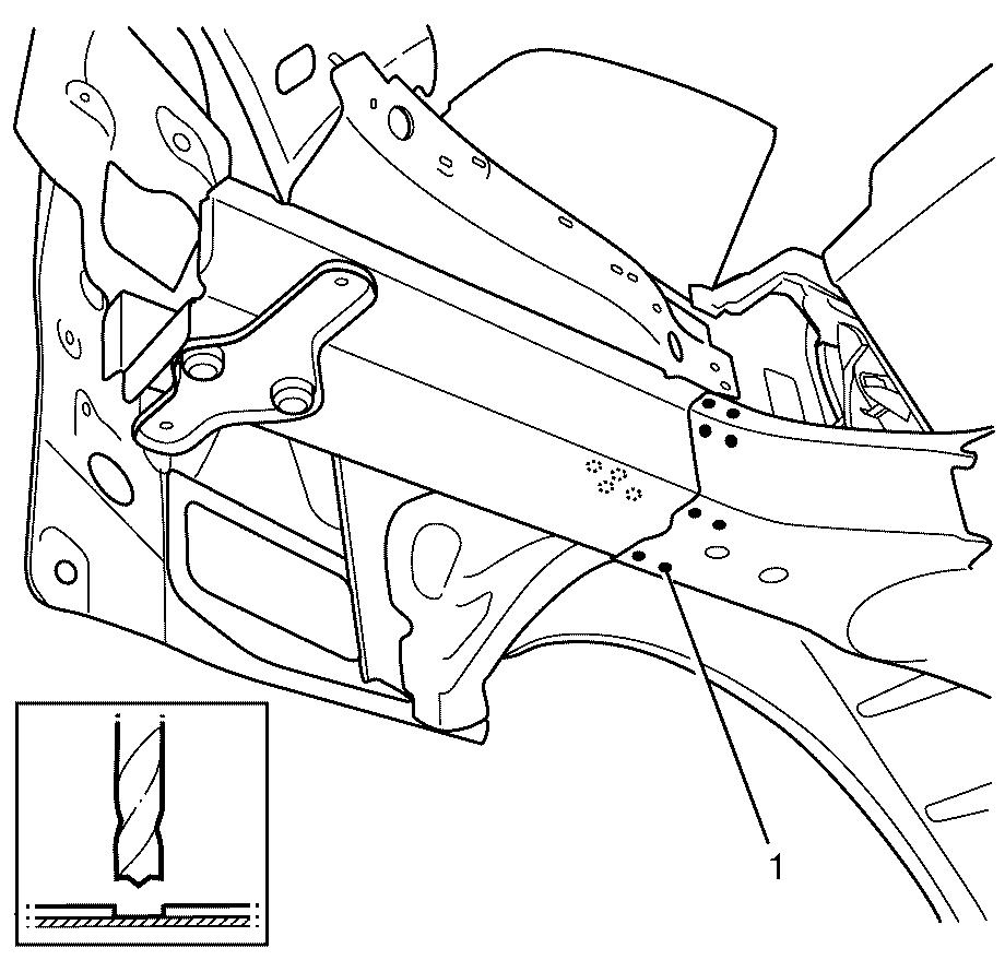
- Locate, mark and drill out all factory welds (1) attaching the rear rail to the underbody.
- Remove the damaged rail section from the vehicle.
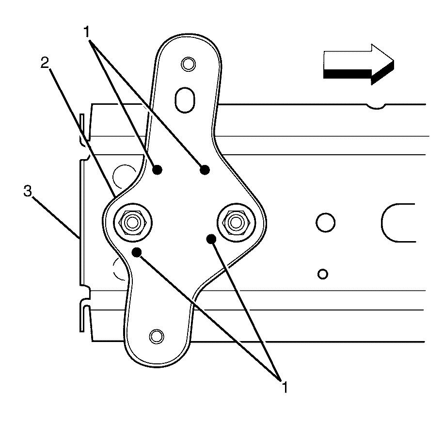
- Locate, mark and drill out the factory welds (1) attaching the exhaust hanger mounting bracket (2) to the rear rail (3). Left hand rail shown, right hand is mirror image.
Caution: Refer to Approved Equipment for Collision Repair Caution in the Preface section.
Caution: Refer to Safety Glasses Caution in the Preface section.
Caution: Refer to Foam Sound Deadeners Caution in the Preface section.
Important: This procedure should be used if the damage is rearward of the factory joint in the rail assembly.
Caution: Refer to Battery Disconnect Caution in the Preface section.
Important: Do not damage any inner panels or reinforcements.
Important: Note the number and location of welds for installation of the service assembly.
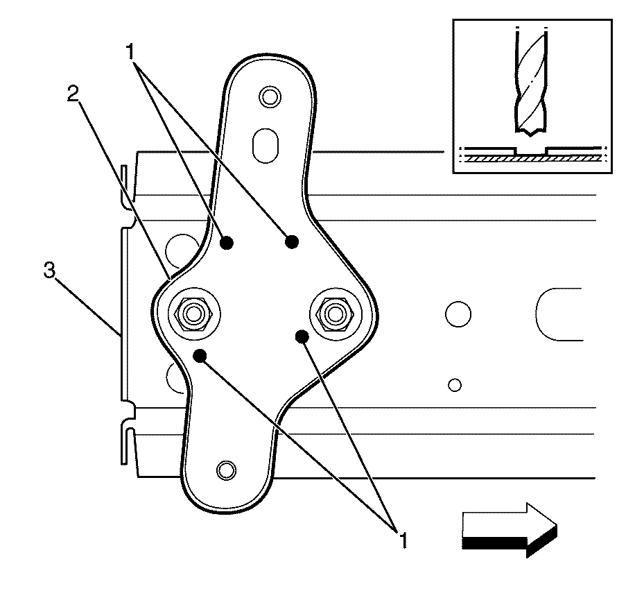
Important: The following step is only required if the old exhaust bracket is undamaged and is to be re-used with the new rear rail.
Installation Procedure
- Drill 8 mm (5/16 in ) puddle weld holes in the service part, as necessary, in the locations puddle welding is needed.
- Prepare the mating surfaces, as necessary.
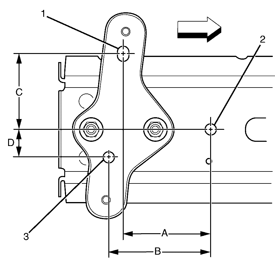
- Align the exhaust hanger bracket to the new rear rail (left hand rail shown, right hand is mirror image). Dimensions are as follows: A = 95 mm; B = 111 mm; C = 79 mm; D = 30 mm. Datum hole identification as follows: 1 = 13.1x17.5mm; 2 = 13.1mm dia; 3 = 13.1mm dia.
- Apply structural adhesive GM6449G or equivalent to all mating surfaces.
- Weld (1) the exhaust hanger mounting bracket (2) to the rear rail (3).
- Align the new rear rail to the vehicle using the datum points (1) and (2). Datum points (1) and (2) are 13.1mm dia holes. Refer to Dimensions - Body.
- Weld (1) the rear rail to the underbody.
- Clean and prepare all welded surfaces.
- Install the rear end panel. Refer to Rear End Panel Replacement.
- Install the body side inner panel extension. Refer to Body Side Inner Panel Extension Replacement.
- Apply sealers and anti-corrosion materials to the repair area, as necessary. Refer to Anti-Corrosion Treatment and Repair.
- Paint the repaired area. Refer to Basecoat/Clearcoat Paint Systems.
- Install the spare wheel carrier. Refer to Spare Wheel Carrier Replacement.
- Install the spare wheel and emergency kit to the rear compartment.
- Install the sound deadening materials to the locations recorded on removal.
- Install the rear frame. Refer to Rear Frame Replacement.
- Install the rear muffler hanger bracket. Refer to Exhaust Hanger Mounting Bracket Replacement.
- Install the rear bumper bracket. Refer to Rear Bumper Bracket Replacement.
- Install the rear muffler heat shields. Refer to Exhaust Muffler Heat Shield Replacement - Right Side or Exhaust Muffler Heat Shield Replacement - Left Side.
- Install the rear muffler assembly. Refer to Exhaust Muffler Replacement - Left Side or Exhaust Muffler Replacement - Right Side.
- Install the liftgate. Refer to Liftgate Replacement.
- Install the tail lights. Refer to Tail Lamp Assembly and /or Backup, Sidemarker, Stop, Turn Signal Bulb Replacement.
- Install the pressure relief valve. Refer to Pressure Relief Valve Replacement.
- Install the battery tray. Refer to Battery Tray Replacement.
- Install the battery. Refer to Battery Replacement.
- Install the quarter inner trim finish panel. Refer to Quarter Inner Trim Finish Panel Replacement.
- Install the liftgate weatherstrip. Refer to Liftgate Weatherstrip Replacement.
- Install the load floor stationary panel carpet. Refer to Load Floor Stationary Panel Carpet Replacement.
- Install the rear compartment floor panel carpet. Refer to Rear Compartment Floor Panel Carpet Replacement.
- Install the rear end trim finish panel. Refer to Rear End Trim Finish Panel Replacement.
- Install the rear bumper impact bar. Refer to Rear Bumper Impact Bar Replacement.
- Install the rear bumper fascia. Refer to Rear Bumper Fascia Replacement.
- Connect the negative battery cable. Refer to Battery Negative Cable Disconnection and Connection.
- Enable the SIR system. Refer to SIR Disabling and Enabling.
Important: This part has structural weld-thru adhesive in the joint areas. Replace this with additional spot welds at the attachment points. This can be accomplished by adding an additional weld between each factory weld in all areas.
Important: If the location of the original spot weld holes can not be determined, or if structural weld-thru adhesive is present, space the puddle weld holes every 32 mm (1¼ in).
Important: Ensure that all factory welds are replaced in their original locations.
Important: Ensure that all structural adhesives and sealers are replaced in their original locations.
Important: Spot welding is the preferred method for attaching panels and should be used wherever possible. A puddle weld should be performed where your spot welder is unable to reach.
