Fuel Hose and Pipes Engine Compartment Hoses
Removal Procedure
Notice:
• Do not repair the fuel feed or return pipes. • Replace the fuel feed and return pipes with original equipment
or with parts that meet the GM specifications for those parts. The replacement
pipe must have the same type of fittings as the original pipe in order to
ensure the integrity of the connection.
Tools Required
J 37088-A, tool set, Fuel Line Quick-Connect Separator
- Disconnect the negative battery cable.
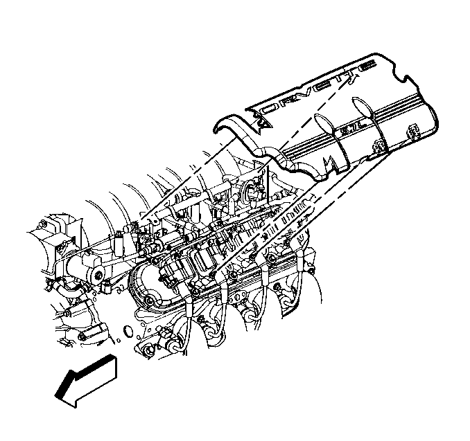
- Remove the left fuel rail cover.
- Relieve the fuel system pressure. Refer to the Fuel Pressure Relief .
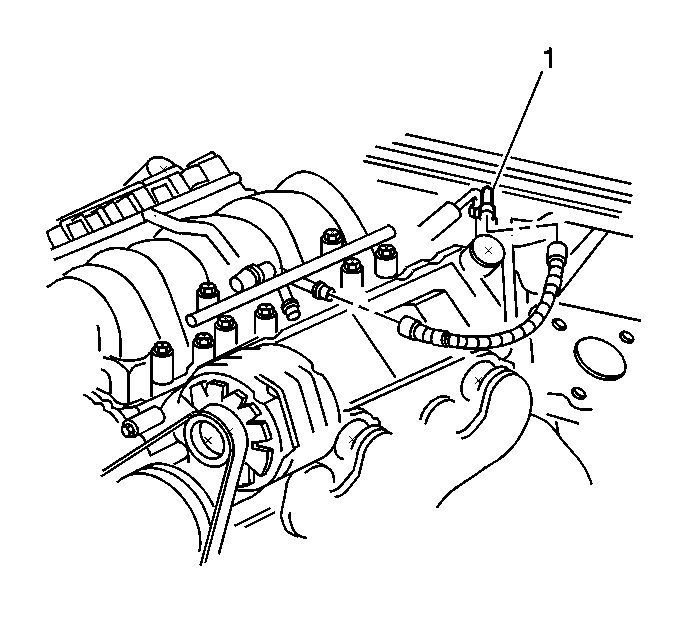
- Disconnect the quick-connect fittings at the fuel rail. Refer to Servicing Quick Connect Fittings .
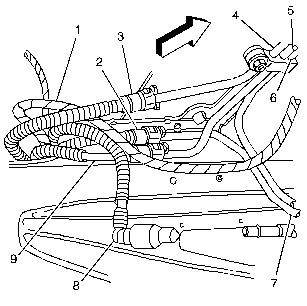
- Disconnect the quick-connect fittings at the chassis fuel pipes (1 and 2).
- Remove the fuel feed hose (3) and the fuel return hose (4).
- Cap the fuel pipes in order to prevent possible fuel system contamination.
- Inspect the hoses for bends, kinks, chafing and cracks. Replace the hoses as required.
Installation Procedure
- Remove the caps from the fuel pipes.
- Connect the fuel feed and return hoses to the chassis fuel pipes (1 and 2). Refer to Servicing Quick Connect Fittings .
- Connect the fuel feed hose (3) and the fuel return hose (4) to the fuel rail.
- Tighten the fuel filler cap.
- Connect the negative battery cable.
- Inspect for leaks.
- Install the left fuel rail cover.


| 6.1. | Turn the ignition switch ON for 2 seconds. |
| 6.2. | Turn the ignition switch OFF for 10 seconds. |
| 6.3. | Turn the ignition switch ON. |
| 6.4. | Check for fuel leaks. |
Fuel Hose and Pipes Chassis Pipes
Removal Procedure
Caution: Provide additional support when a vehicle is on a hoist in the following
ways:
• Before removing parts, support the opposite end. This helps prevent
the vehicle from slipping off. • Before removing major components, chain the vehicle frame to the
hoist pads at the same end as the removal. This helps avoid a tip-off.
Notice:
• Do not repair the fuel feed or return pipes. • Replace the fuel feed and return pipes with original equipment
or with parts that meet the GM specifications for those parts. The replacement
pipe must have the same type of fittings as the original pipe in order to
ensure the integrity of the connection.
Tools Required
J 37088-A, Tool Set, Fuel Line Quick-Connect Separator
- Disconnect the negative battery cable.
- Relieve the fuel system pressure. Refer to the Fuel Pressure Relief .
- Remove the engine assembly. Refer to Engine Replacement in Engine Mechanical.
- Remove the transmission assembly. Refer to Transmission Replacement in the Automatic Transmission - 4L60-E or Transmission Replacement in the Manual Transmission - MM6.
- Drain the fuel tanks. Refer to Draining Fuel Tanks .
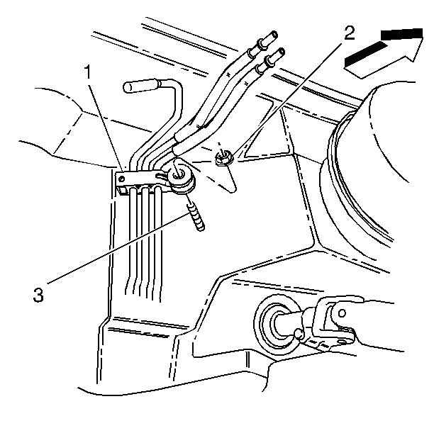
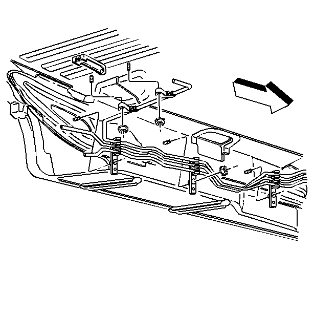
- Disconnect the chassis fuel and EVAP pipe retainer (1) from the upper front of dash mounting stud (3).
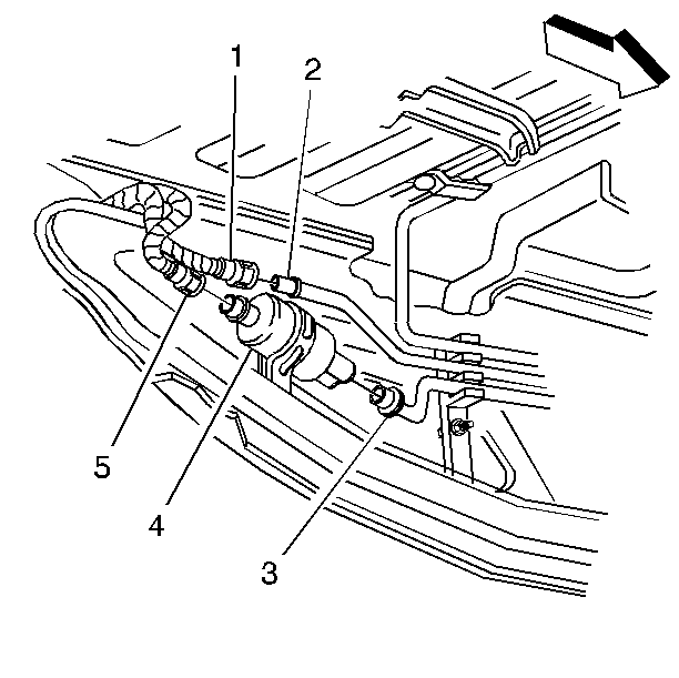
- Disconnect the chassis fuel feed pipe (3) from the fuel filter.
- Cap the open end of the fuel filter (4).
- Disconnect the chassis fuel return pipe (7) from the fuel return rear pipe (2) near the fuel filter area.
- Cap the open end of the fuel return rear pipe (2).
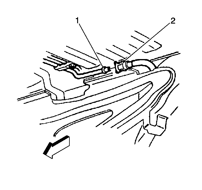
- Disconnect the chassis EVAP pipe (1) at the rear EVAP pipe (2).
- Cap the rear EVAP pipe.
- Disconnect the chassis fuel and EVAP pipes from the underbody retainers.
- Remove the chassis fuel and EVAP pipes.
Installation Procedure
Important:
• Follow the same routing as the original pipes. • Secure the pipes in order to prevent chafing. • Do not kink or bend the pipes.
- Install the chassis fuel and EVAP pipes into the underbody retainers.
- Uncap the rear EVAP pipe.
- Connect the chassis EVAP pipe (1) to the rear EVAP pipe (2).
- Uncap the fuel return rear pipe (2).
- Connect the chassis fuel return pipe (7) to the fuel return rear pipe (2) near the fuel filter area.
- Uncap the fuel filter outlet.
- Connect the chassis fuel feed pipe (3) to the fuel filter (4).
- Refer to the
Notice: Use the correct fastener in the correct location. Replacement fasteners must be the correct part number for that application. Fasteners requiring replacement or fasteners requiring the use of thread locking compound or sealant are identified in the service procedure. Do not use paints, lubricants, or corrosion inhibitors on fasteners or fastener joint surfaces unless specified. These coatings affect fastener torque and joint clamping force and may damage the fastener. Use the correct tightening sequence and specifications when installing fasteners in order to avoid damage to parts and systems.
in Cautions and Notices. - Install the transmission assembly. Refer to Transmission Replacement in the Automatic Transmission - 4L60-E section or Transmission Replacement in the Manual Transmission - MM6 section.
- Install the engine assembly. Refer to Engine Replacement in the Engine Mechanical section.
- Refill the fuel system.
- Tighten the fuel filler cap.
- Connect the negative battery cable.
- Inspect for leaks.


Connect the chassis fuel and EVAP pipe retainer (1) at the upper front of dash mounting stud (3).
Tighten
Tighten all of the pipe retainer nuts to 3 N·m (27 lb in).
| 14.1. | Turn the ignition switch ON for 2 seconds. |
| 14.2. | Turn the ignition switch OFF for 10 seconds. |
| 14.3. | Turn the ignition switch ON. |
| 14.4. | Check for fuel leaks. |
Fuel Hose and Pipes Rear Pipes
Removal Procedure
Notice: Replace the EVAP pipes and hoses with the original equipment or parts that meet the GM specifications for those parts. The replacement EVAP pipe must have the same type of fittings as the original pipe in order to ensure the integrity of the connection. When replacing EVAP hoses, use only reinforced fuel-resistant hose identified with the word Fluoroelastomer or GM 6163-M on the hose. The inside hose diameter must match the outside pipe diameter. Do not use rubber hose within 100 mm (4 in) of any part of the exhaust system or within 254 mm (10 in) of the catalytic converter.
Notice:
• Do not repair the fuel feed or return pipes. • Replace the fuel feed and return pipes with original equipment
or with parts that meet the GM specifications for those parts. The replacement
pipe must have the same type of fittings as the original pipe in order to
ensure the integrity of the connection.
- Remove the left fuel tank. Refer to Fuel Tank Replacement .
- Disconnect the fuel sender fuel feed pipe (3) (jet pump to left tank).
- Disconnect the fuel feed pipe (8) at the fuel filter.
- Disconnect the fuel feed rear crossover pipe (9) (left tank to jet pump).
- Disconnect the fuel return rear pipe (2).
- Remove the left side rear fuel pipes.
- Cap the fuel filter inlet.
- Cap the chassis fuel return pipe.
- Remove the right fuel tank. Refer to Fuel Tank Replacement .
- Disconnect the EVAP purge pipe (2) at the chassis EVAP purge pipe (1).
- Cap the chassis EVAP purge pipe.
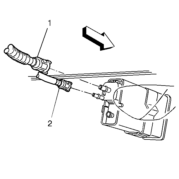
- Disconnect the fuel tanks to canister EVAP pipe (2) at the canister.
- Disconnect the EVAP purge pipe (1) at the canister.
- Remove the right rear wheelhouse liner panel. Refer to Rear Wheelhouse Liner Panel in Body Rear End.
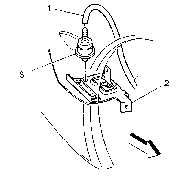
- Disconnect the fuel tank vent valve hose (1) at the fuel tank vent valve (3).
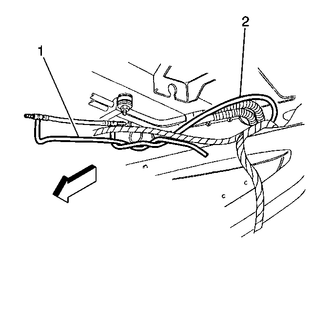
- Remove the rear EVAP pipes (1) and the EVAP hose (5) from the following straps:
- Remove the rear EVAP pipes and the EVAP hose.
- Remove the two rear upper fuel and EVAP pipe retainers.
- Remove the fuel sender fuel feed pipe (4) (jet pump to left tank).
- Remove the fuel feed rear crossover pipe (5) (left tank to jet pump).


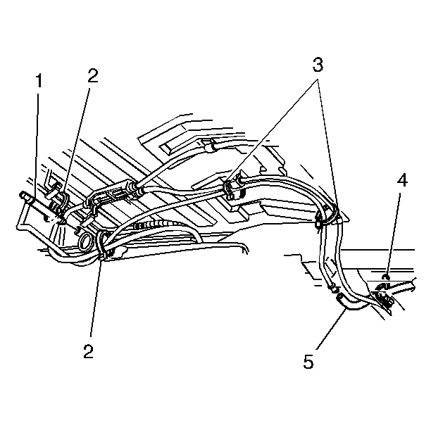
| • | The straps attached to the fuel pipes (2). |
| • | The straps attached to the parking brake cable (3). |
| • | The strap attached to the rear wheelhouse liner brace (4). |


Installation Procedure
Important: Mark or identify each fuel pipe in order to aid in installing the pipes in their original positions.
- Install the fuel feed rear crossover pipe (5) (left tank to jet pump).
- Install the fuel sender fuel feed pipe (4) (jet pump to left tank).
- Refer to the
Notice: Use the correct fastener in the correct location. Replacement fasteners must be the correct part number for that application. Fasteners requiring replacement or fasteners requiring the use of thread locking compound or sealant are identified in the service procedure. Do not use paints, lubricants, or corrosion inhibitors on fasteners or fastener joint surfaces unless specified. These coatings affect fastener torque and joint clamping force and may damage the fastener. Use the correct tightening sequence and specifications when installing fasteners in order to avoid damage to parts and systems.
in Cautions and Notices. - Route the fuel tanks to canister EVAP pipe (2) through the right tunnel reinforcement opening.
- Route the EVAP purge pipe through the right tunnel reinforcement opening.
- Connect the fuel tanks to canister EVAP pipe (2) to the canister.
- Connect the EVAP purge pipe (1) to the canister.
- Remove the cap from the chassis EVAP purge pipe.
- Connect the EVAP purge pipe (2) to the chassis EVAP purge pipe (1).
- Connect the fuel tank vent valve hose (1) to the fuel tank vent valve (3).
- Connect the fuel tank vent valve hose (5) to the rear wheelhouse liner brace (4) with 1 strap.
- Connect the fuel tank vent valve pipe (1) to the fuel pipes (2) with 2 straps.
- Connect the fuel tank vent valve pipe to the parking brake cable (3) with 2 straps.
- Remove the cap from the chassis fuel return pipe.
- Install and connect the fuel return rear pipe (2).
- Install and connect the fuel feed rear crossover pipe (9) (left tank to jet pump).
- Remove the cap from the fuel filter inlet.
- Install and connect the fuel feed pipe (8) at the fuel filter.
- Install and connect the fuel sender fuel feed pipe (3) (jet pump to left tank).
- Install the right fuel tank. Refer to Fuel Tank Replacement .
- Install the left fuel tank. Refer to Fuel Tank Replacement .
- Tighten the fuel filler cap.
- Connect the negative battery cable.
- Inspect for leaks.


Install the two rear upper fuel and EVAP pipe retainers.
Tighten
Tighten the fuel and EVAP pipe retainer nuts to 3 N·m (27 lb
in).


| 24.1. | Turn the ignition switch ON for 2 seconds. |
| 24.2. | Turn the ignition switch OFF for 10 seconds. |
| 24.3. | Turn the ignition switch ON. |
| 24.4. | Check for fuel leaks. |
