For 1990-2009 cars only
Removal Procedure
Tools Required
| • | J 21854-01 Pivot Pin Remover |
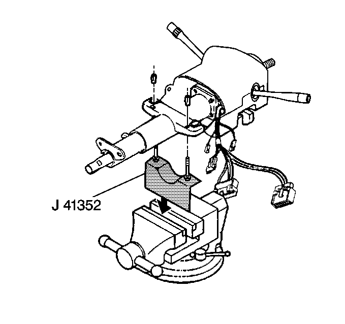
| • | J 41352 Modular Column Holding Fixture |
- Remove the lower and upper shrouds. Refer to Steering Column Trim Cover Replacement - Off Vehicle .
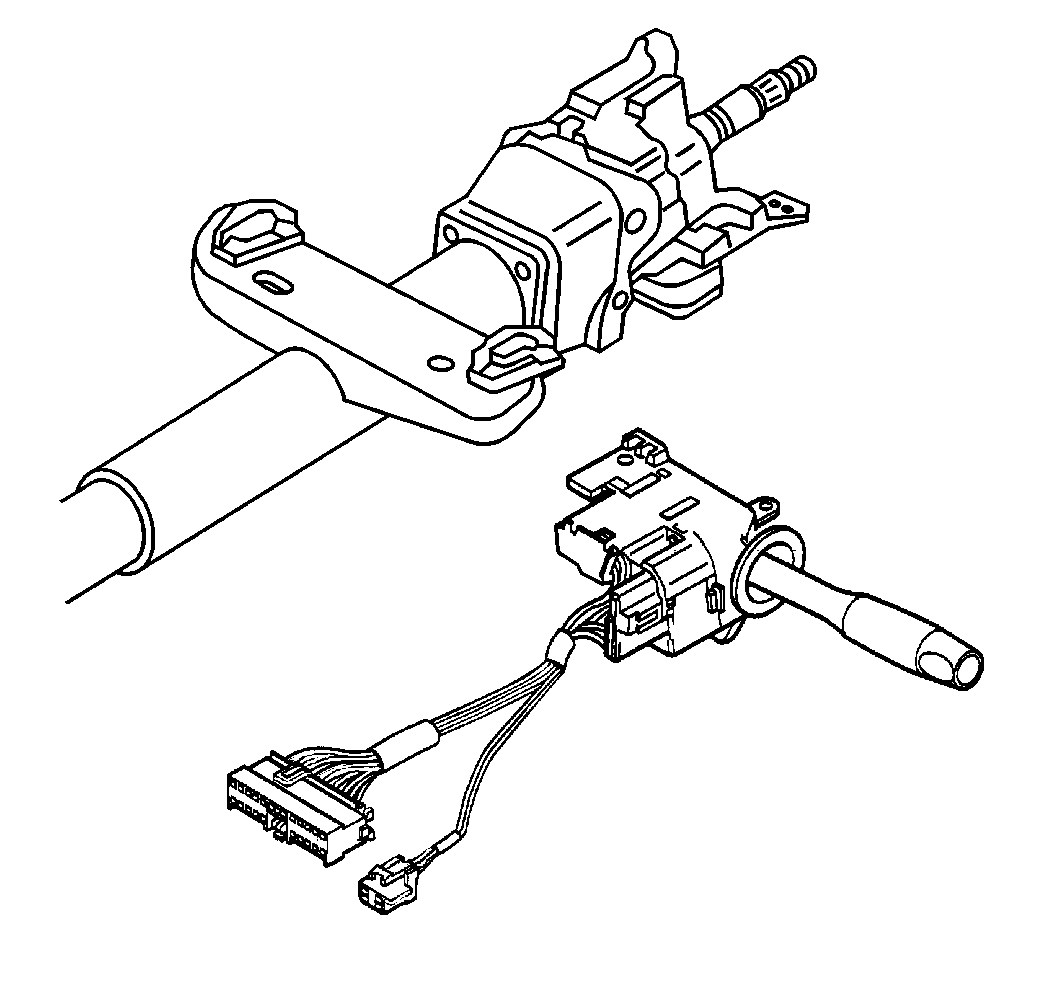
- Remove the turn signal and multifunction switch assembly.
- Remove the tilt spring. Refer to Tilt Spring - Off Vehicle .
- Remove the steering wheel position sensor. Refer to Steering Wheel Position Sensor Replacement
- Remove the adapter and bearing assembly from the jacket assembly.
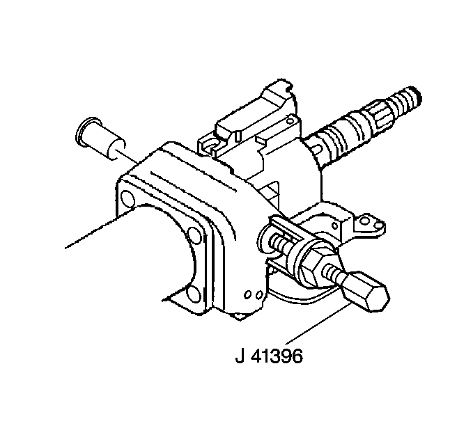
- Use tool J 21854-01 to remove the two pivot pins.
- Perform the following steps to remove the steering column tilt head assembly with the steering shaft assembly:
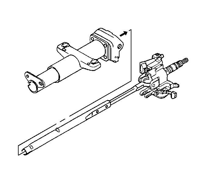
| 7.1. | Mark the race and upper shaft assembly and mark the lower steering shaft to ensure proper assembly. Failure to assemble properly will cause steering wheel to be turned 180 degrees. |
| 7.2. | Install and pull the tilt arm to disengage the steering wheel lock shoes from the dowel pins in the steering column support assembly. |
Disassembly Procedure
- Remove the lower steering shaft assembly from the race and upper shaft assembly and the steering column tilt head assembly.
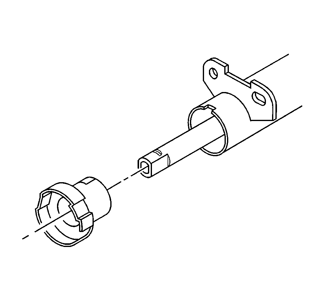
- Perform the following steps to remove the race and upper shaft assembly from the lower steering shaft assembly:
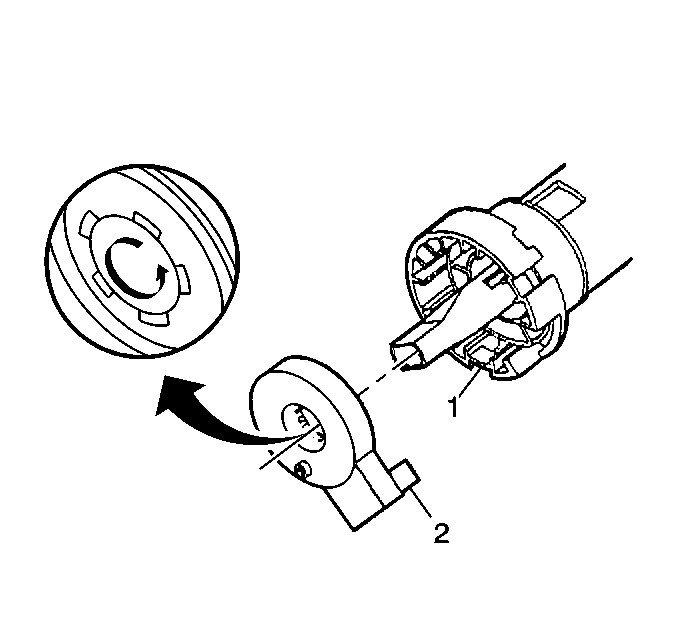
- Perform the following steps to remove the centering sphere from the upper shaft assembly:
- Remove the shaft preload spring from the centering sphere.
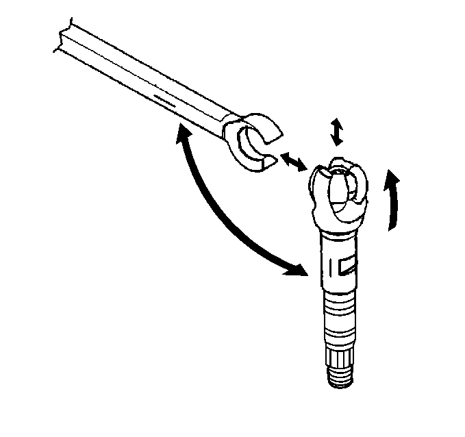
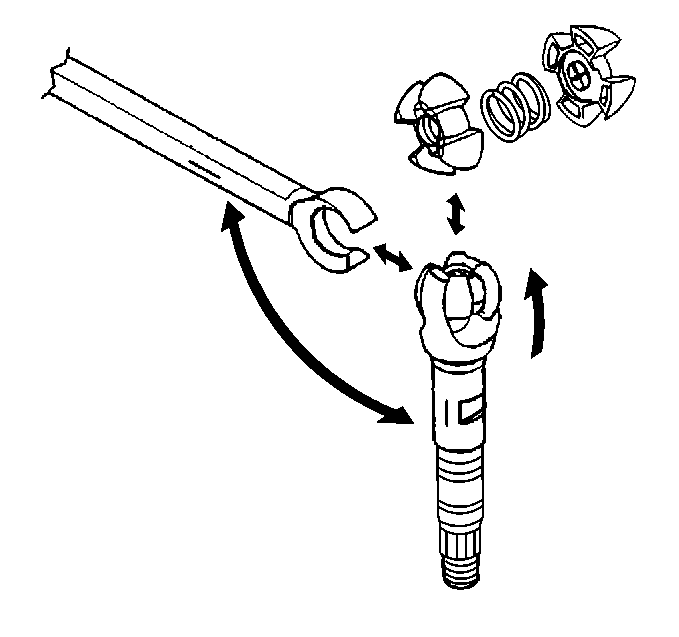
| 2.1. | Tilt 90 degrees to each other. |
| 2.2. | Disengage. |
| 3.1. | Rotate the sphere 90 degrees. |
| 3.2. | Slip the sphere out of the upper shaft assembly. |
Assembly Procedure
- Lower the steering shaft assembly to the race and upper shaft assembly and the steering column tilt head assembly.
- Assemble the shaft preload spring to the centering sphere.
- Perform the following steps to assemble the centering sphere:
- Perform the following steps to lower the steering shaft assembly to the race and upper shaft assembly:
- Remove the four torx head screws.
- Remove the steering column support assembly.
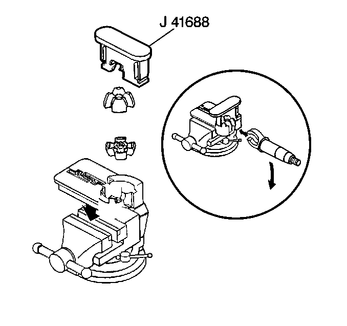
| 3.1. | Lubricate the centering sphere with lithium grease. |
| 3.2. | Slip the centering sphere into the upper shaft assembly. |
| 3.3. | Rotate the centering sphere 90 degrees. |

| 4.1. | Line up the marks. |
| 4.2. | Tilt the assemblies 90 degrees to each other. |
Disassembly Procedure
- Remove the lower steering shaft assembly from the race and upper shaft assembly and the steering column tilt head assembly.
- Perform the following steps to remove the race and upper shaft assembly from the lower steering shaft assembly:
- Perform the following steps to remove the centering sphere from the upper shaft assembly:
- Remove the shaft preload spring from the centering sphere.


| 2.1. | Tilt 90 degrees to each other. |
| 2.2. | Disengage. |
| 3.1. | Rotate the sphere 90 degrees. |
| 3.2. | Slip the sphere out of the upper shaft assembly. |
Assembly Procedure
- Lower the steering shaft assembly to the race and upper shaft assembly and the steering column tilt head assembly.
- Assemble the shaft preload spring to the centering sphere.
- Perform the following steps to assemble the centering sphere:
- Perform the following steps to lower the steering shaft assembly to the race and upper shaft assembly:
- Remove the four torx head screws.
- Remove the steering column support assembly.

| 3.1. | Lubricate the centering sphere with lithium grease. |
| 3.2. | Slip the centering sphere into the upper shaft assembly. |
| 3.3. | Rotate the centering sphere 90 degrees. |

| 4.1. | Line up the marks. |
| 4.2. | Tilt the assemblies 90 degrees to each other. |
Installation Procedure
- Install the column support assembly.
- Install the four torx head screws.
- Repeat steps 1 through 4 of the Steering Column Tilt Head ASM Installation Procedure. Refer to Steering Column Tilt Head - Off Vehicle .
- Install the upper tilt head components. Refer to Upper Tilt Head Components .
- Install the turn signal and multifunction switch assembly to the column.
- Perform the following steps to install the adapter and bearing assembly to the steering column jacket assembly:
- Install the sensor retainer.
- Install the SIR coil. Refer to Inflatable Restraint Steering Wheel Module Coil Replacement - Off Vehicle .
- Install the lower and upper shrouds. Refer to Steering Column Trim Cover Replacement - Off Vehicle .
Tighten
Tighten the screws to 9 N·m (80 lb in).
Notice: Use the correct fastener in the correct location. Replacement fasteners must be the correct part number for that application. Fasteners requiring replacement or fasteners requiring the use of thread locking compound or sealant are identified in the service procedure. Do not use paints, lubricants, or corrosion inhibitors on fasteners or fastener joint surfaces unless specified. These coatings affect fastener torque and joint clamping force and may damage the fastener. Use the correct tightening sequence and specifications when installing fasteners in order to avoid damage to parts and systems.

Tighten
Tighten the screws to 6 N·m (53 lb in).
| 6.1. | Position the tab on the adapter and bearing assembly with the slot in the steering column jacket assembly. |
| 6.2. | Push together the tab into the slot in the steering column jacket assembly. |
