Fuel Tank Replacement Right
Tools Required
| • | J 34730-1A Fuel Pressure Gauge |
| • | J 37088-A Tool Set, Fuel Line Quick Connect Separator |
Removal Procedure
- Disconnect the negative battery cable.
- Relieve the fuel system pressure. Refer to the Fuel Pressure Relief .
- Drain the fuel tanks. Refer to Fuel Tank Draining .
- Raise the vehicle. Refer to Lifting and Jacking the Vehicle in General Information.
- Remove the right rear tire and wheel. Refer to Tire and Wheel Removal and Installation in Tires and Wheels.
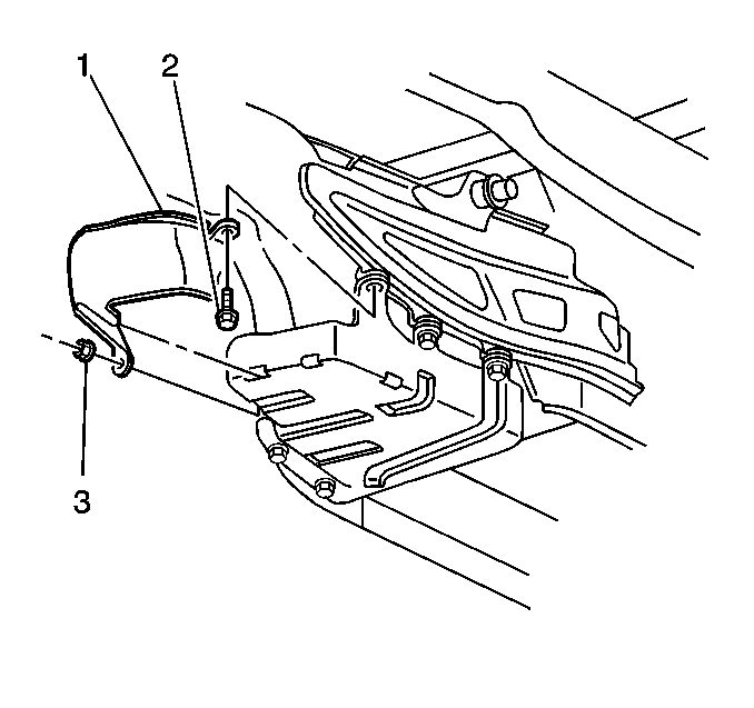
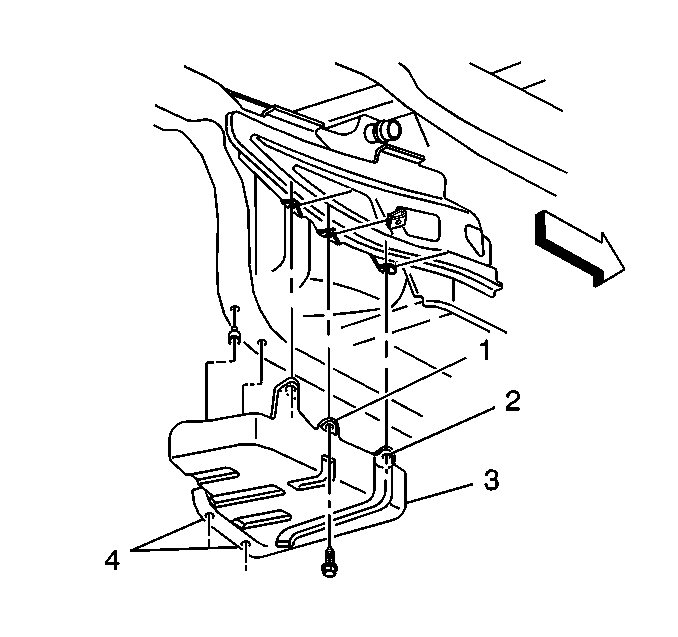
- Remove the fuel tank shield mount nut (3).
- Remove the fuel tank shield mount bolt (2).
- Remove the fuel tank shield (1).
- Remove the right muffler, for automatic transmission-equipped vehicles only. Refer to Exhaust Muffler Replacement - Left Side or Exhaust Muffler Replacement - Right Side in Engine Exhaust.
- Disconnect the fuel sender electrical connector.
- Mark or identify each fuel pipe in order to aid in installing the pipes in their original positions.
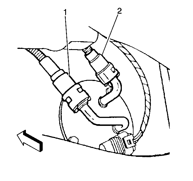
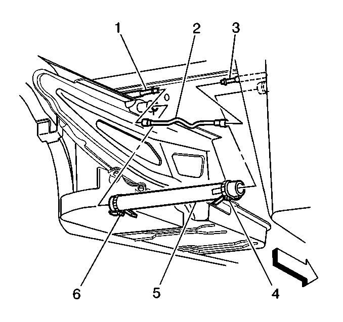
- Disconnect the auxiliary fuel return rear pipe (1) that connects the jet pump to the left tank and the auxiliary fuel feed rear pipe (2) that connects the left tank to the jet pump at the fuel sender. Refer to Plastic Collar Quick Connect Fitting Service .
- Cap the fuel pipes in order to prevent possible fuel system contamination.
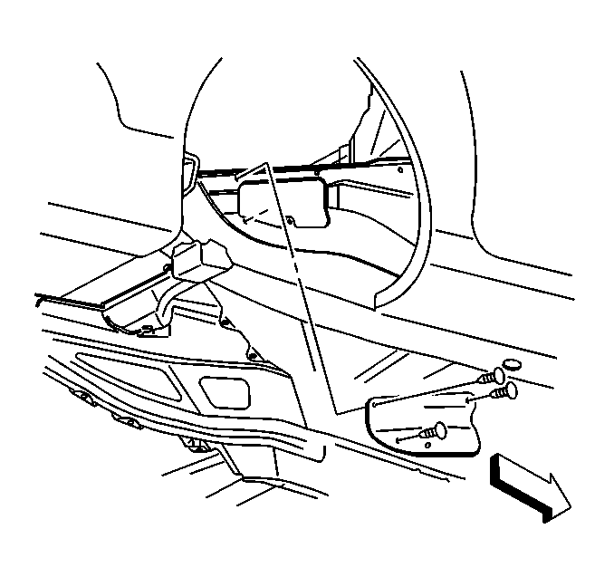
- Remove the right rear wheelhouse panel. Refer to Wheelhouse Panel Replacement in Body Rear End.
- Remove the EVAP canister access cover.
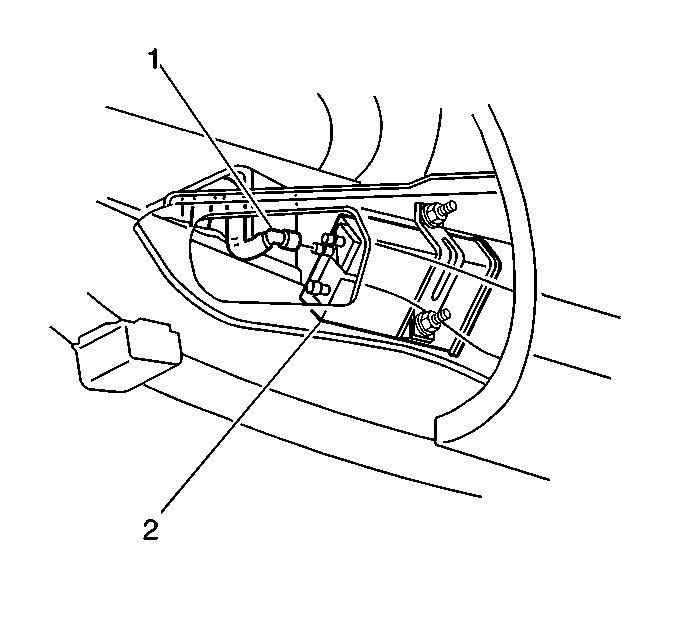
- Disconnect the FLVV hose (1) at the EVAP canister (2).
- Disconnect the fuel pressure sensor electrical connector.
- Disconnect the tank crossover hose (5).
- Disconnect the EVAP pipe (2) quick connect fitting at the right fuel tank EVAP pipe (3).
- Cap the EVAP pipe in order to prevent possible contamination.
- Remove the fuel tank strap mount bolts (1, 2, 4)
- Remove the fuel tank strap (3).
- Remove the fuel tank.
Caution: Unless directed otherwise, the ignition and start switch must be in the OFF or LOCK position, and all electrical loads must be OFF before servicing any electrical component. Disconnect the negative battery cable to prevent an electrical spark should a tool or equipment come in contact with an exposed electrical terminal. Failure to follow these precautions may result in personal injury and/or damage to the vehicle or its components.
Caution: To avoid any vehicle damage, serious personal injury or death when major components are removed from the vehicle and the vehicle is supported by a hoist, support the vehicle with jack stands at the opposite end from which the components are being removed and strap the vehicle to the hoist.
Installation Procedure
Important: Always replace the fuel system hose clamps with the original equipment or parts that meet the GM specifications for those parts when replacing the clamps.
- Install the fuel tank.
- Install the fuel tank strap (3).
- Install the fuel tank strap bolts (1, 2, 4).
- Tighten the bolt (2) to 25 N·m (18 lb ft).
- Tighten the bolt (1) to 25 N·m (18 lb ft).
- Tighten the remaining bolts (4) to 25 N·m (18 lb ft).
- Remove the cap from the EVAP pipe.
- Connect the EVAP pipe (2) quick connect fitting at the right fuel tank EVAP pipe (3).
- Connect the tank crossover hose (5).
- Push the clamp (4) outboard against the fuel tank, keeping the clamp parallel with the white stripe on the tank crossover hose.
- Connect the fuel pressure sensor electrical connector.
- Connect the FLVV hose (1) at the EVAP canister (2).
- Install the EVAP canister access cover.
- Install the right rear wheelhouse panel. Refer to Wheelhouse Panel Replacement in Body Rear End.
- Remove the caps from the fuel pipes.
- Connect the auxiliary fuel return rear pipe (1) from the jet pump to the left tank, and the auxiliary fuel feed rear pipe (2) from the left tank to the jet pump. Refer to Plastic Collar Quick Connect Fitting Service .
- Connect the fuel sender electrical connector.
- Install the right muffler, for automatic transmission- equipped vehicles only. Refer to Exhaust Muffler Replacement - Left Side or Exhaust Muffler Replacement - Right Side in Engine Exhaust.
- Install the fuel tank shield (1).
- Install the fuel tank shield mount bolt (2).
- Install the fuel tank shield mount nut (3).
- Install the right rear tire and wheel. Refer to Tire and Wheel Removal and Installation in Tires and Wheels.
- Lower the vehicle.
- Refill the fuel system.
- Connect the negative battery cable.
- Perform the following procedure in order to inspect for leaks:
- Program the transmitters. Refer to Transmitter Programming in Keyless Entry.


Notice: Use the correct fastener in the correct location. Replacement fasteners must be the correct part number for that application. Fasteners requiring replacement or fasteners requiring the use of thread locking compound or sealant are identified in the service procedure. Do not use paints, lubricants, or corrosion inhibitors on fasteners or fastener joint surfaces unless specified. These coatings affect fastener torque and joint clamping force and may damage the fastener. Use the correct tightening sequence and specifications when installing fasteners in order to avoid damage to parts and systems.
Tighten

Tighten
Tighten the tank crossover hose clamp to 4 N·m
(35 lb in).


Tighten
| • | Tighten the fuel tank shield mount bolt to 25 N·m (18 lb ft). |
| • | Tighten the fuel tank shield mount nut to 12 N·m (106 lb in). |
| 23.1. | Turn the ignition switch ON for 2 seconds. |
| 23.2. | Turn the ignition switch OFF for 10 seconds. |
| 23.3. | Turn the ignition switch ON. |
| 23.4. | Inspect for fuel leaks. |
Fuel Tank Replacement Left
Tools Required
| • | J 34730-1A Fuel Pressure Gauge |
| • | J 37088-A Tool Set, Fuel Line Quick Connect Separator |
Removal Procedure
- Disconnect the negative battery cable.
- Relieve the fuel system pressure. Refer to the Fuel Pressure Relief .
- Drain the fuel tanks. Refer to Fuel Tank Draining .
- Raise the vehicle. Refer to Lifting and Jacking the Vehicle in General Information.
- Remove the left rear tire and wheel. Refer to Tire and Wheel Removal and Installation in Tires and Wheels.
- Remove the left rear wheelhouse panel. Refer to Wheelhouse Panel Replacement in Body Rear End.
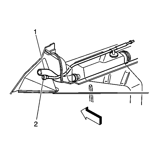
- Disconnect the fuel fill hose (1) and the vent pipe (2).
- Remove the fuel tank shield mount nut (3).
- Remove the fuel tank shield mount bolt (2).
- Remove the fuel tank shield (1).
- Remove the left muffler, for automatic transmission-equipped vehicles only. Refer to Exhaust Muffler Replacement - Left Side , or refer to Exhaust Muffler Replacement - Right Side in Engine Exhaust.
- Disconnect the fuel sender electrical connector.
- Mark or identify each fuel pipe in order to aid in installing the pipes in their original positions.
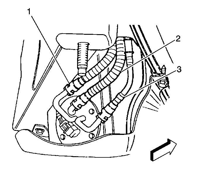
- Disconnect the auxiliary fuel return rear pipe (1) from the jet pump to the left tank, the fuel return rear pipe (2), and the fuel feed rear pipe (3) at the fuel sender. Refer to Plastic Collar Quick Connect Fitting Service .
- Cap the fuel pipes in order to prevent possible fuel system contamination.
- Disconnect the tank crossover hose (5).
- Disconnect the EVAP pipe quick-connect fitting (2) at the left fuel tank EVAP pipe (1).
- Cap the EVAP pipe in order to prevent possible contamination.
- Remove the fuel tank strap mount bolts (1, 2, 4).
- Remove the fuel tank strap (3).
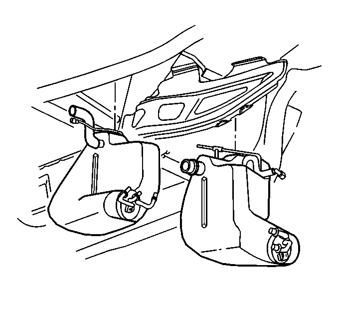
- Remove the fuel tank.
Caution: Unless directed otherwise, the ignition and start switch must be in the OFF or LOCK position, and all electrical loads must be OFF before servicing any electrical component. Disconnect the negative battery cable to prevent an electrical spark should a tool or equipment come in contact with an exposed electrical terminal. Failure to follow these precautions may result in personal injury and/or damage to the vehicle or its components.
Caution: Provide additional support when a vehicle is on a hoist in the following
ways:
• Before removing parts, support the opposite end. This helps prevent
the vehicle from slipping off. • Before removing major components, chain the vehicle frame to the
hoist pads at the same end as the removal. This helps avoid a tip-off.



Installation Procedure
Important: When replacing the fuel system hose clamps, always replace the clamps with the original equipment or parts that meet the GM specifications for those parts.
- Install the fuel tank.
- Install the fuel tank strap (3).
- Install the fuel tank strap bolts (1, 2, 4).
- Tighten the bolt (2) to 25 N·m (18 lb ft).
- Tighten the bolt (1) to 25 N·m (18 lb ft).
- Tighten the remaining bolts (4) to 25 N·m (18 lb ft).
- Remove the cap from the EVAP pipe.
- Connect the EVAP pipe (2) quick-connect fitting at the left fuel tank EVAP pipe (1).
- Install the tank crossover hose (5).
- Push the clamp outboard against the fuel tank keeping the clamp parallel with the white stripe on the tank crossover hose.
- Remove the caps from the fuel pipes.
- Connect the auxiliary fuel return rear pipe (1) from the jet pump to the left tank, the fuel return rear pipe (2), and the fuel feed rear pipe (3) to the fuel sender. Refer to Plastic Collar Quick Connect Fitting Service .
- Connect the fuel sender electrical connector.
- Install the left muffler, for automatic transmission- equipped vehicles only. Refer to Exhaust Muffler Replacement - Left Side or Exhaust Muffler Replacement - Right Side in Engine Exhaust.
- Install the fuel tank shield (1).
- Install the fuel tank shield mount bolt (2).
- Install the fuel tank shield mount nut (3).
- Connect the fuel fill hose (1) and the vent pipe (2).
- Install the left rear wheelhouse panel. Refer to Wheelhouse Panel Replacement in Body Rear End.
- Install the left rear tire and wheel. Refer to Tire and Wheel Removal and Installation in Tires and Wheels.
- Lower the vehicle.
- Refill the fuel system.
- Connect the negative battery cable.
- Perform the following procedure in order to inspect for leaks:
- Program the transmitters. Refer to Transmitter Programming in Keyless Entry.


Notice: Use the correct fastener in the correct location. Replacement fasteners must be the correct part number for that application. Fasteners requiring replacement or fasteners requiring the use of thread locking compound or sealant are identified in the service procedure. Do not use paints, lubricants, or corrosion inhibitors on fasteners or fastener joint surfaces unless specified. These coatings affect fastener torque and joint clamping force and may damage the fastener. Use the correct tightening sequence and specifications when installing fasteners in order to avoid damage to parts and systems.
Tighten

Tighten
Tighten the tank crossover hose clamp to 4 N·m
(35 lb in).


Tighten
| • | Tighten the fuel tank shield mount bolt to 25 N·m (18 lb ft). |
| • | Tighten the fuel tank shield mount nut to 12 N·m (106 lb in). |

Tighten
Tighten the fuel fill hose clamp to 4.0 N·m
(35 lb in).
| 21.1. | Turn the ignition switch ON for 2 seconds. |
| 21.2. | Turn the ignition switch OFF for 10 seconds. |
| 21.3. | Turn the ignition switch ON. |
| 21.4. | Inspect for fuel leaks. |
Fuel Tank Replacement Right W/FFS
Tools Required
J 37088-A Fuel Line Disconnect tool
Removal Procedure
- Disconnect the negative battery cable. Refer to Battery Negative Cable Disconnection and Connection in Engine Electrical.
- Drain the fuel tank. Refer to Fuel Tank Draining .
- Raise and support the vehicle. Refer to Lifting and Jacking the Vehicle in General Information.
- Remove the right rear tire. Refer to Tire and Wheel Removal and Installation in Tires and Wheels.
- Remove the right rear wheelhouse panel. Refer to Wheelhouse Panel Replacement in Body Rear End.
- Remove the EVAP canister access cover.
- Disconnect the FLVV hose (1) at the EVAP Canister (2).
- Disconnect the fuel pump module harness connector.
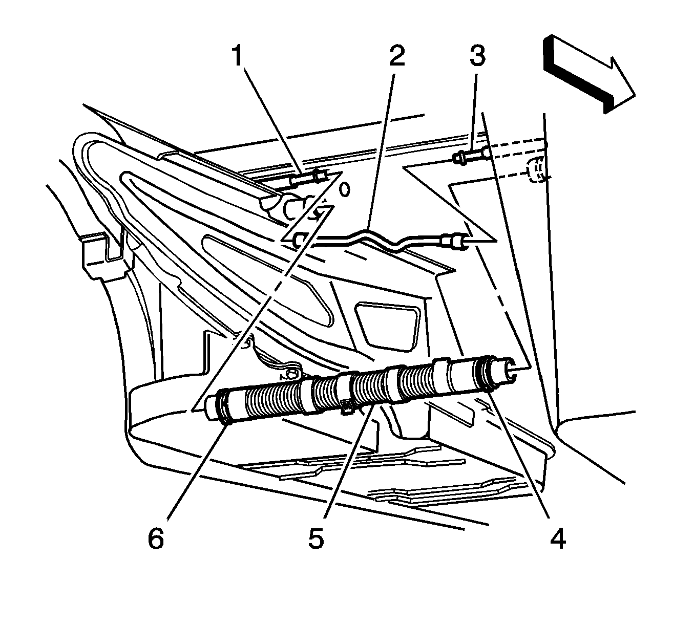
- Remove the crossover tube from the clamp located above the transmission.
- Disengage the crossover tube CPA retainer by pulling the tab (1) outward and rotate.
- Rotate crossover tube collar counter-clockwise to disengage.
- Disconnect the crossover tube from the right fuel tank by pulling the tube straight out of the fuel tank connection.
- Disconnect the EVAP crossover pipe (2) quick connect fitting at the right fuel tank.
- Cap the EVAP pipe to prevent system contamination.
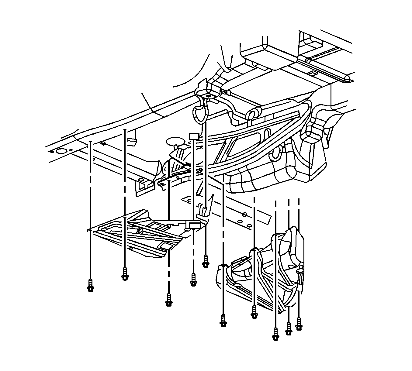
- Remove the fuel tank strap mount bolts.
- Remove the fuel tank strap from the vehicle.
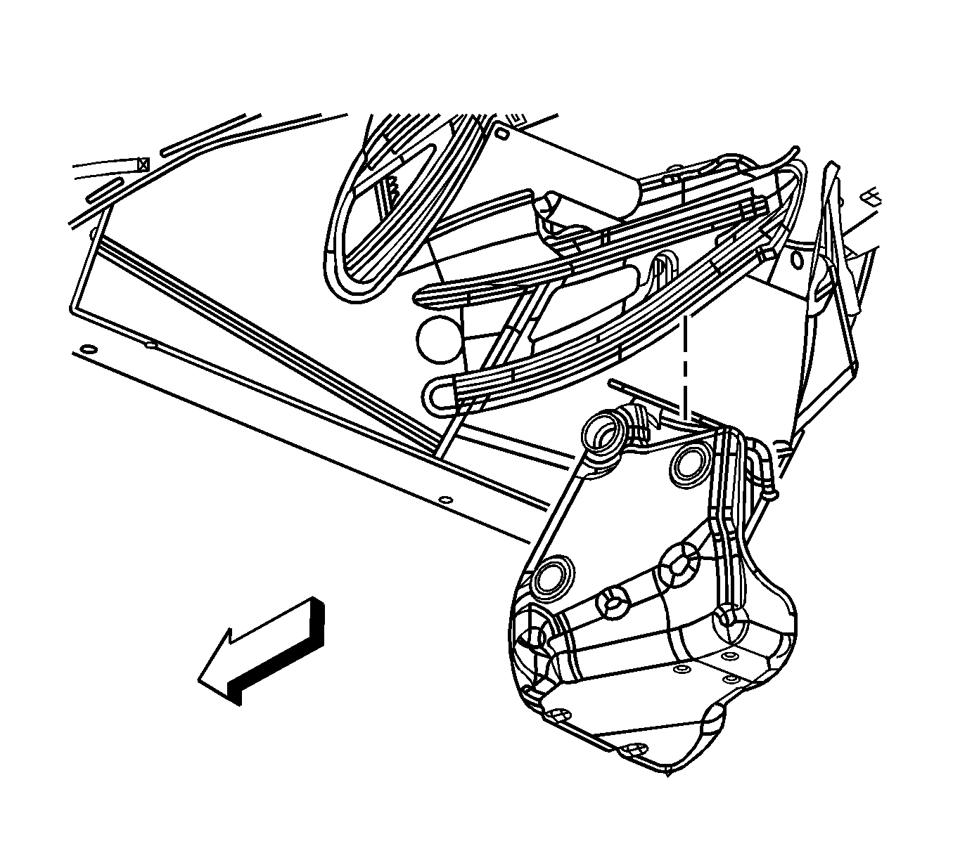
- Remove the fuel tank.

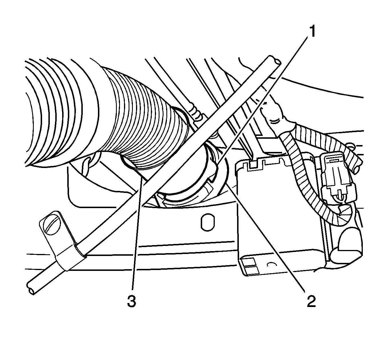
Important: The crossover tube CPA is released when the latch disengages from the tank connection groove.
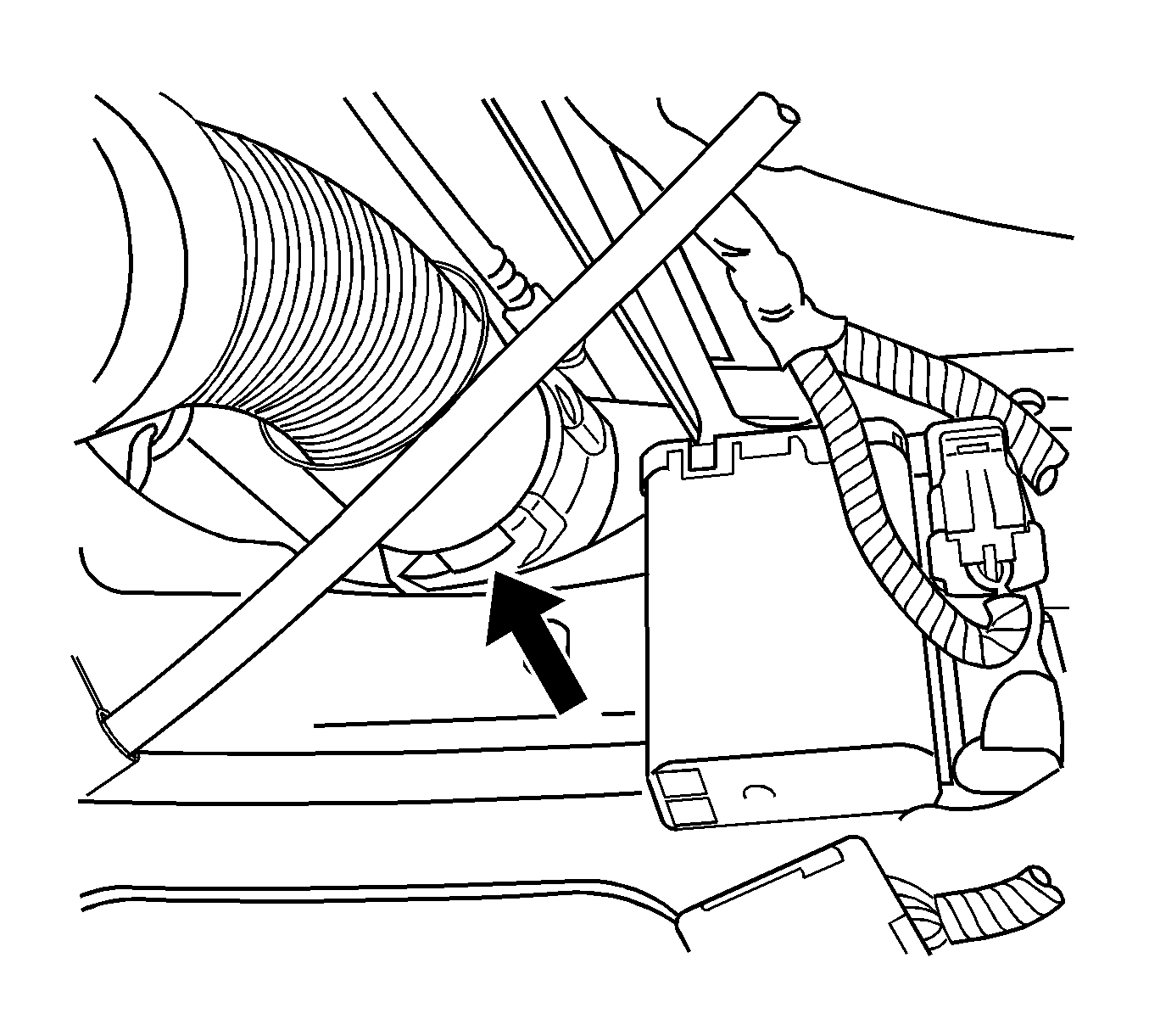
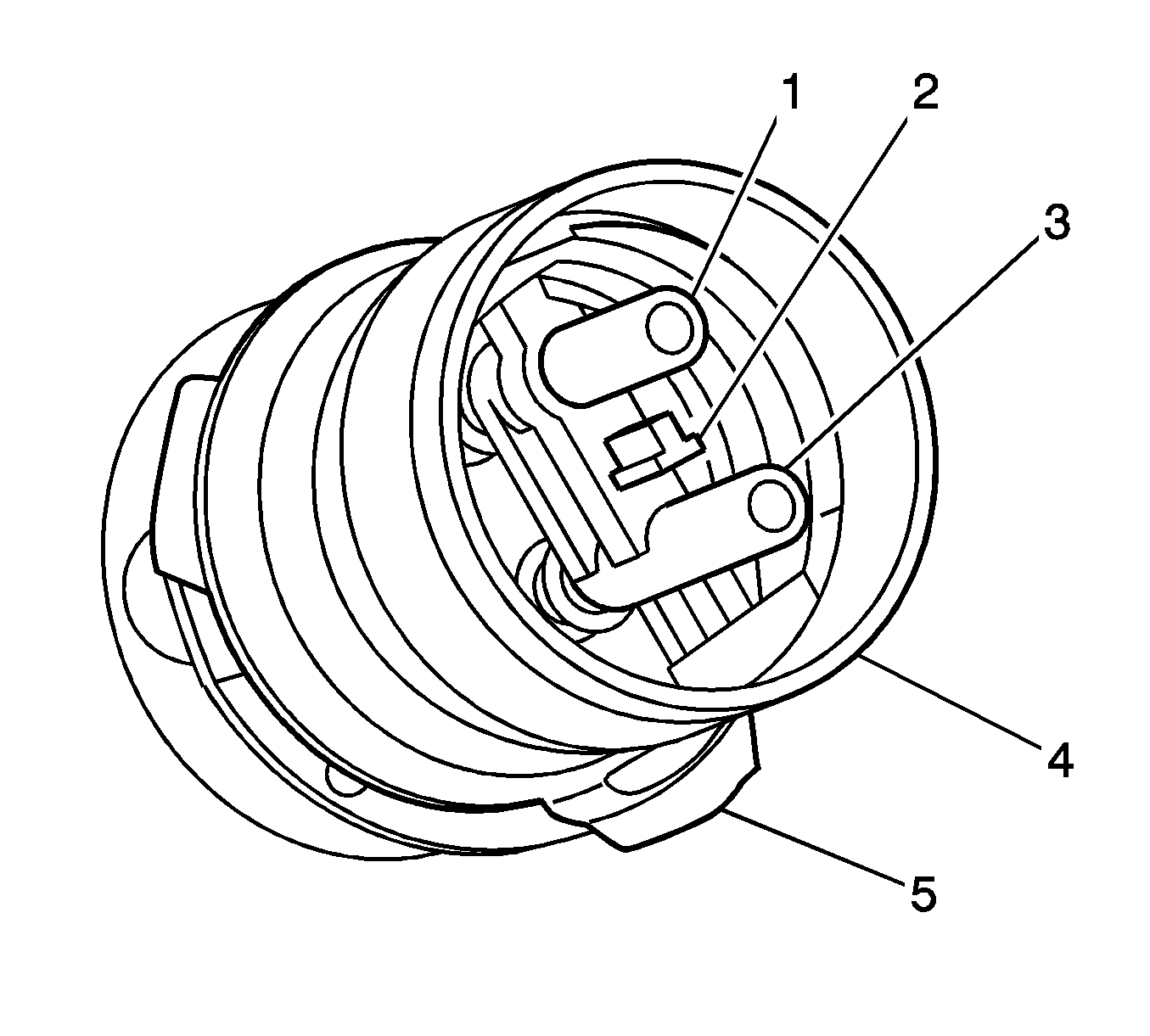
Important: Take care not to disturb the internal O-rings in the fuel tank connections.
Installation Procedure
- Install the fuel tank.
- Install the fuel tank strap to the vehicle.
- Install the fuel tank strap bolts.
- Remove the cap from the EVAP pipe.
- Connect the EVAP crossover pipe (2) quick connect fitting at the right fuel tank.
- Lubricate the crossover tube to fuel tank connection O-rings (1-4) with PN 1051717 rubber lubricant.
- Lubricate the crossover tube O-ring mating surfaces (1-4) with PN 1051717 rubber lubricant.
- Connect the crossover tube to the right fuel tank using the features previously noted.
- Rotate the crossover tube collar (3) clockwise to engage the tangs.
- Rotate the crossover tube CPA retainer counter-clockwise past the collar latching tang and push the tab (1) into the locked position.
- Test the crossover tube to fuel tank connection by attempting to rotate the crossover tube collar counter-clockwise.
- Tighten the fuel tank strap bolts.
- Snap the crossover tube into the clamp located above the transmission.
- Connect the fuel pump module harness connector.
- Connect the FLVV hose (1) at the EVAP Canister (2).
- Install the EVAP canister access cover.
- Install the driveline support assembly. Refer to Driveline Support Assembly Replacement in Propeller Shaft.
- Install the right rear wheelhouse panel. Refer to Wheelhouse Panel Replacement in Body Rear End.
- Install the right rear tire. Refer to Tire and Wheel Removal and Installation in Tires and Wheels.
- Install the left fuel tank. Refer to Fuel Tank Replacement .


Notice: Refer to Fastener Notice in the Preface section.

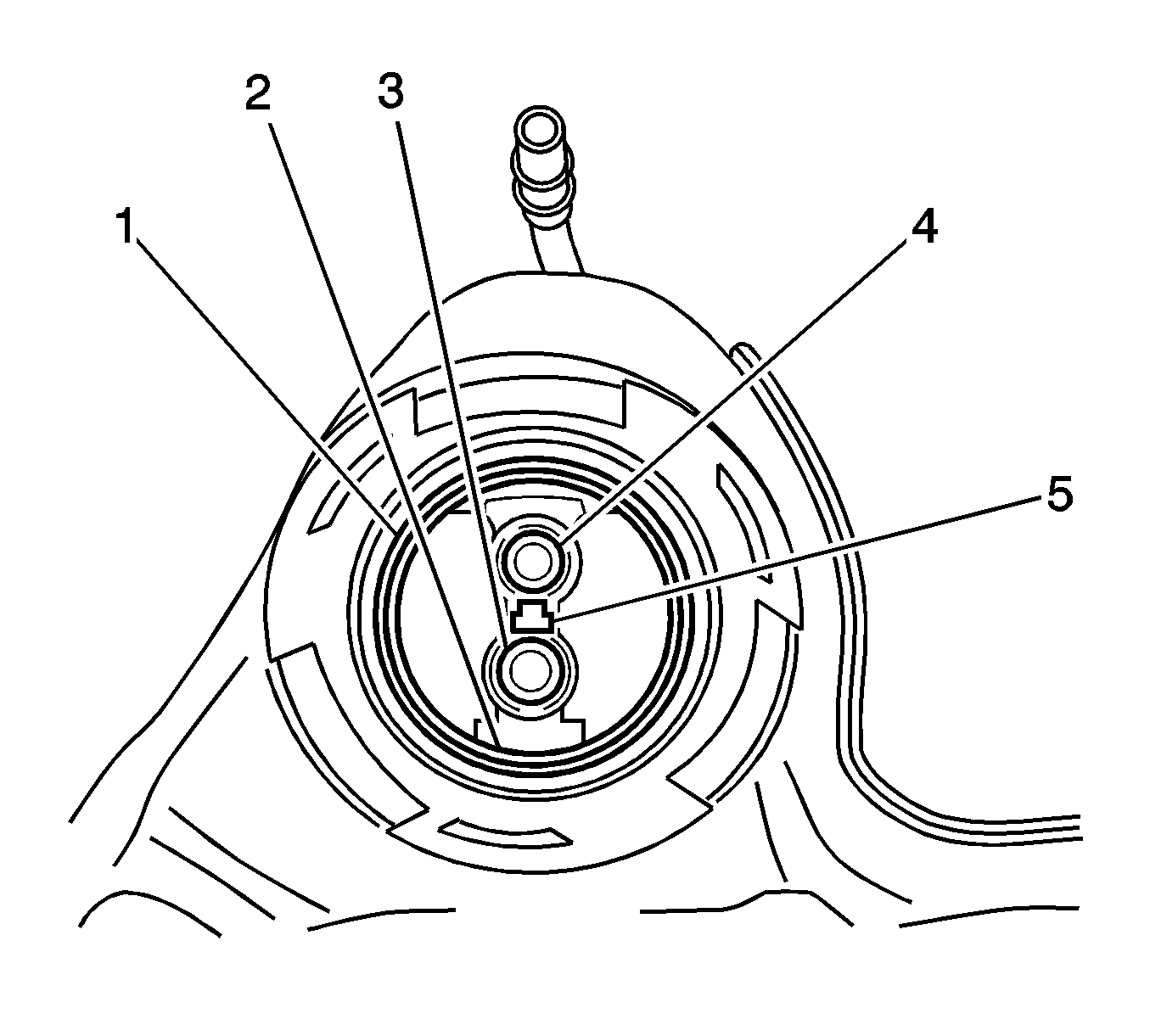
Important: Note the location of the T-shaped alignment feature (5) between the jet pump feed/return pipes connector.

Important: Note the T-shaped alignment feature on the crossover tube.

Important: The crossover tube will not fully seat into the fuel tank if the jet pump lines are misaligned.
Important: The crossover tube collar tangs will not latch if misalignment exists.

Important: If the CPA retainer is locked into position, the crossover tube collar will not rotate.

Tighten
Tighten the bolts to 25 N·m (18 lb in).

Fuel Tank Replacement Left W/FFS
Tools Required
J 37088-A Fuel Line Disconnect tool
Removal Procedure
- Disconnect the negative battery cable. Refer to Battery Negative Cable Disconnection and Connection in Engine Electrical.
- Drain the fuel tank. Refer to Fuel Tank Draining .
- Raise and support the vehicle. Refer to Lifting and Jacking the Vehicle in General Information.
- Remove the Left rear tire. Refer to Tire and Wheel Removal and Installation in Tires and Wheels.
- Remove the left rear wheelhouse panel. Refer to Wheelhouse Panel Replacement in Body Rear End.
- Remove both mufflers. Refer to Exhaust Muffler Replacement - Left Side and Exhaust Muffler Replacement - Right Side in Engine Exhaust.
- Remove the driveline support assembly. Refer to Driveline Support Assembly Replacement in Propeller Shaft.
- Disconnect the fuel fill hose and recirc line from the fill pipe.
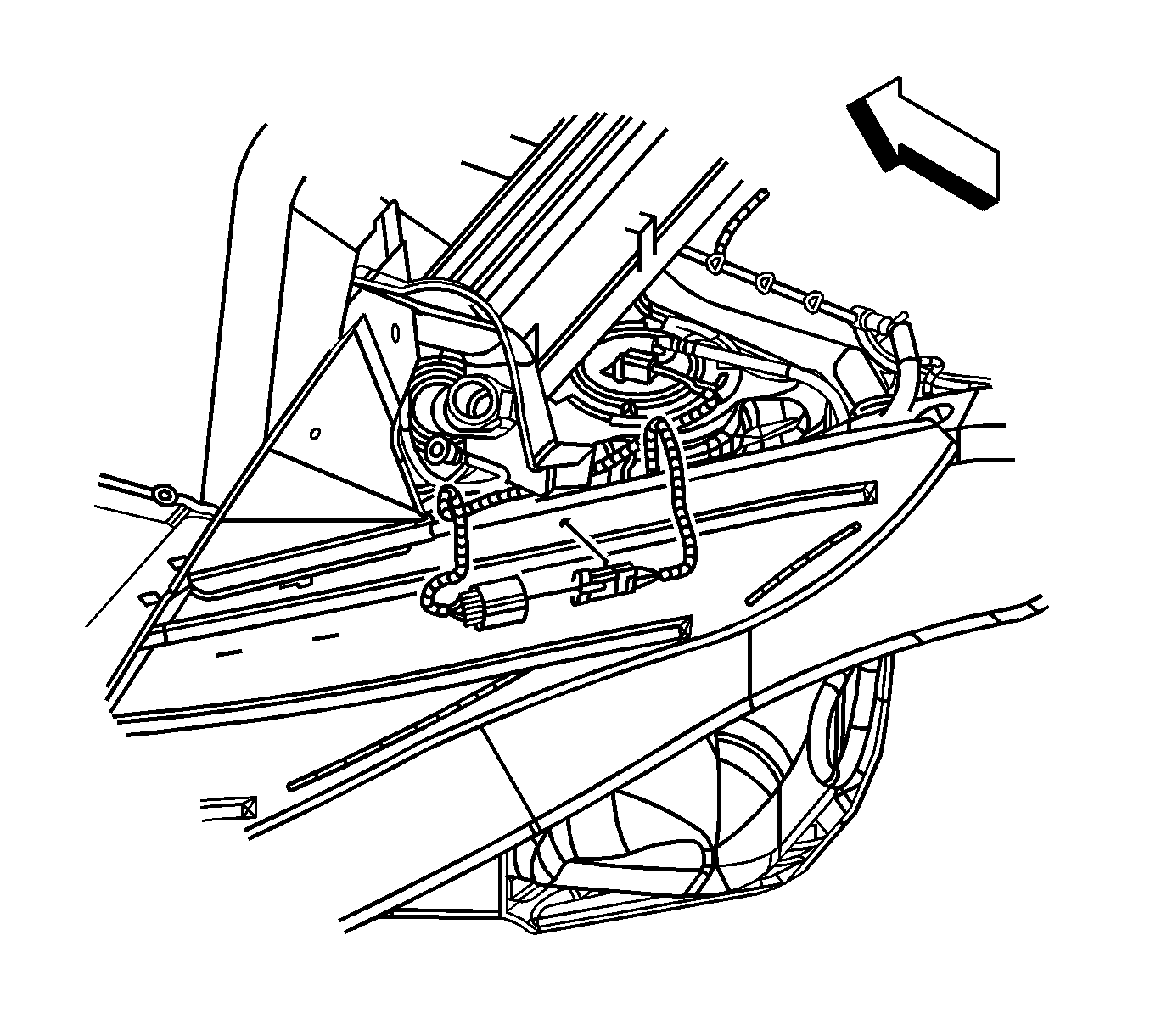
- Disconnect the fuel pump jumper harness connector.
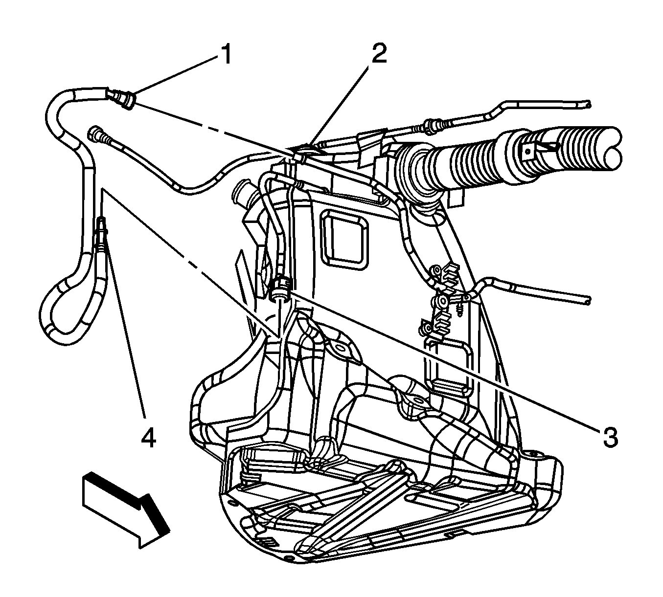
- Disconnect the fuel feed pipe (4) at the rear of the left fuel tank. Refer to Plastic Collar Quick Connect Fitting Service .
- Cap the fuel pipes to prevent fuel system contamination.
- Loosen the fuel tank strap in order to drop the tank approximately one inch.
- Disengage the crossover tube CPA retainer by pulling the tab (1) outward and rotate.
- Rotate crossover tube collar (3) counter-clockwise to disengage.
- Disconnect the crossover tube from the left fuel tank by pulling straight out.
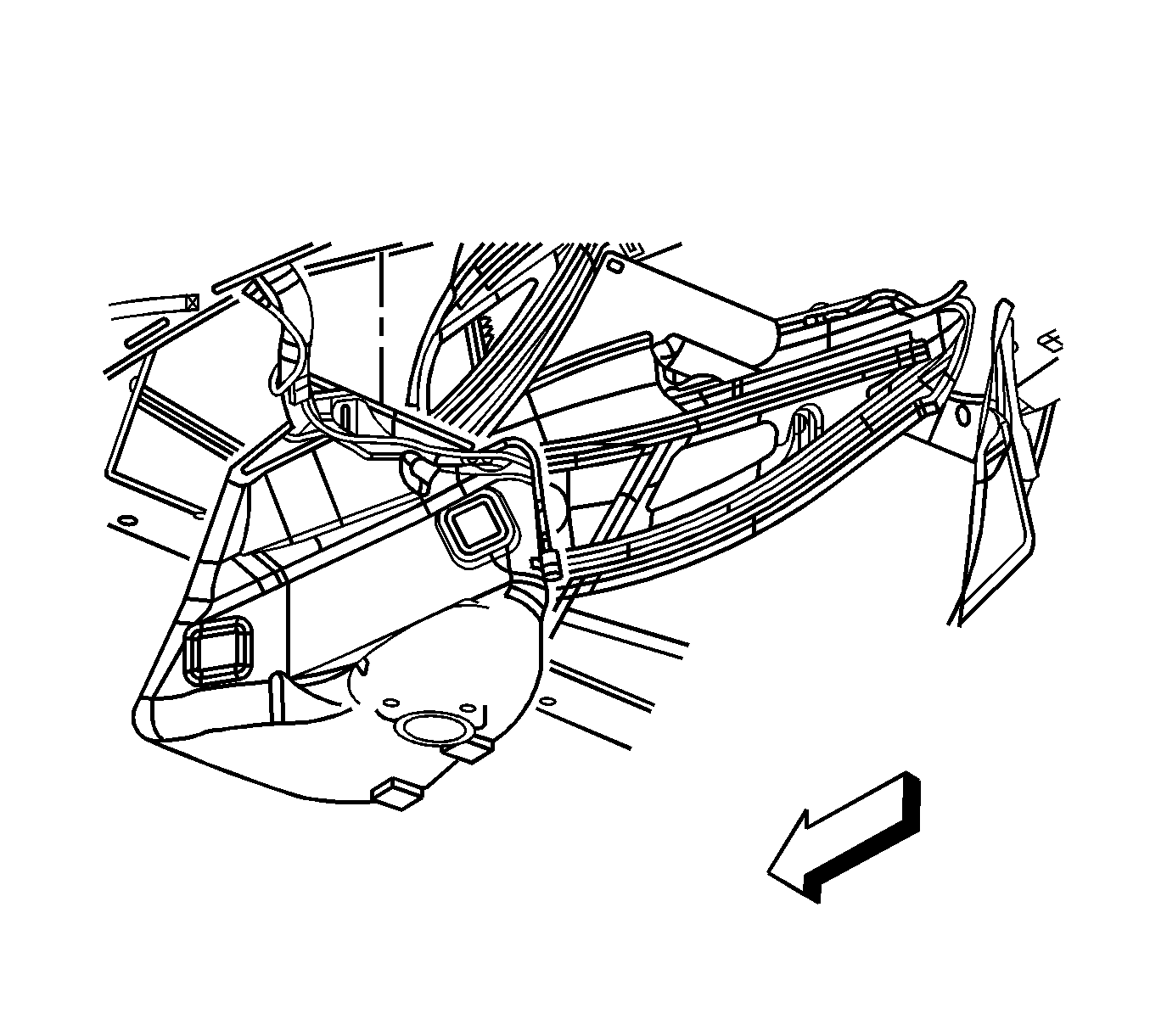
- Disconnect the EVAP crossover pipe (2) quick connect fitting at the left fuel tank.
- Cap the EVAP pipe to prevent system contamination.
- Remove the fuel tank strap mount bolts.
- Remove the fuel tank strap from the vehicle.
- Remove the fuel tank.


Important: The crossover tube CPA is released when the latch disengages from the tank connection groove.


Important: Take care not to disturb the internal O-rings in the fuel tank connections.


Installation Procedure
- Install the fuel tank.
- Install the fuel tank strap to the vehicle.
- Install the fuel tank strap bolts loosely leaving the tank hanging approximately one inch.
- Remove the cap from the EVAP pipe.
- Connect the EVAP crossover pipe (2) quick connect fitting at the left fuel tank.
- Lubricate the crossover tube to fuel tank connection O-rings (1-4) with P/N 1051717 rubber lubricant.
- Lubricate the crossover tube O-ring mating surfaces (1-4) with P/N 1051717 rubber lubricant.
- Connect the crossover tube to the left fuel tank using the features previously noted.
- Rotate the crossover tube collar (3) clockwise to engage the tangs.
- Rotate the crossover tube CPA retainer counter-clockwise past the collar latching tang and push the tab (1) into the locked position.
- Test the crossover tube to fuel tank connection by attempting to rotate the crossover tube collar counter-clockwise.
- Tighten the fuel tank strap bolts.
- Remove the cap from the fuel pipes.
- Connect the fuel feed pipe (4) at the rear of the left fuel tank. Refer to Plastic Collar Quick Connect Fitting Service .
- Connect the fuel pump jumper harness connector.
- Connect the fuel fill hose and recirc line to the fill tube.
- Install the driveline support assembly. Refer to Driveline Support Assembly Replacement in Propeller Shaft.
- Install both mufflers. Refer to Exhaust Muffler Replacement - Left Side and Exhaust Muffler Replacement - Right Side in Engine Exhaust.
- Install the left rear wheelhouse panel. Refer to Wheelhouse Panel Replacement in Body Rear End.
- Install the Left rear tire. Refer to Tire and Wheel Removal and Installation in Tires and Wheels.
- Lower the vehicle.
- Refuel the fuel tank.
- Connect the negative battery cable. Refer to Battery Negative Cable Disconnection and Connection in Engine Electrical.
- Perform the following procedure in order to test for leaks:
- Program the transmitters. Refer to Transmitter Programming in Keyless Entry.


Important: Note the location of the T-shaped alignment feature (5) between the jet pump feed/return pipes connector.

Important: Note the T-shaped alignment feature on the crossover tube.

Important: The crossover tube will not fully seat into the fuel tank if the jet pump lines are misaligned.
Important: The crossover tube collar tangs will not latch if misalignment exists.

Important: If the CPA retainer is locked into position, the crossover tube collar will not rotate.
Notice: Refer to Fastener Notice in the Preface section.

Tighten
Tighten the bolts to 25 N·m (18 lb in).


Tighten
Tighten the clamp to 4 N·m (35 lb in).
| 24.1. | Turn ON the Ignition switch, for 2 seconds. |
| 24.2. | Turn OFF the ignition, for 10 seconds. |
| 24.3. | Turn ON the ignition. |
| 24.4. | Inspect for fuel leaks. |
