Water Pump Replacement 4.3L, 5.0L, and 5.7L
Removal Procedure
- Disconnect the negative battery cable from the battery terminal.
Refer to
Battery Negative Cable Disconnection and Connection
in Engine Electrical.
- Remove the air cleaner assembly. Refer to one of the following
procedures:
- Drain the engine cooling system. Refer to
Cooling System Draining and Filling
.
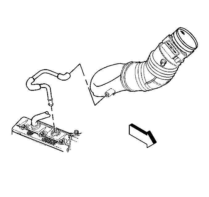
- Remove the air intake
duct from the throttle body.
- Remove the coolant recovery reservoir. Refer to
Coolant Recovery Reservoir Replacement
.
- Remove the upper fan shroud. Refer to
Fan Shroud Replacement
.
- Remove the fan clutch assembly from the vehicle. Refer to
Fan Clutch Replacement
.
- Remove the drive belt from the vehicle. Refer to one of the following
procedures:
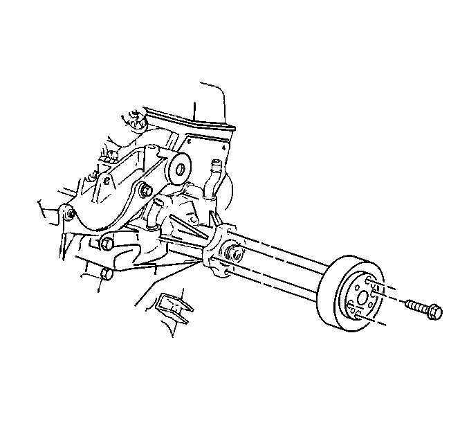
- Remove the water pump
pulley mounting bolts.
- Remove the water pump pulley from the water pump.
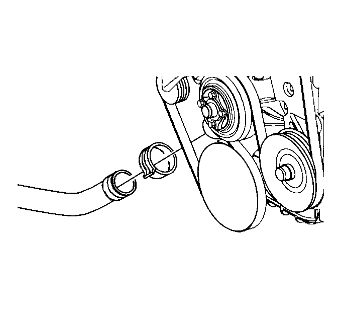
- Disconnect the radiator
outlet hose from the water pump.
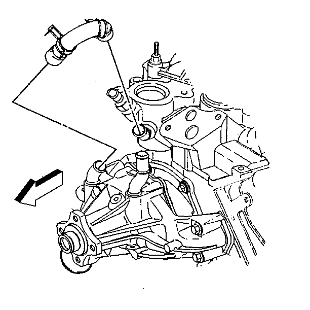
- Disconnect the by-pass
hose from the water pump.
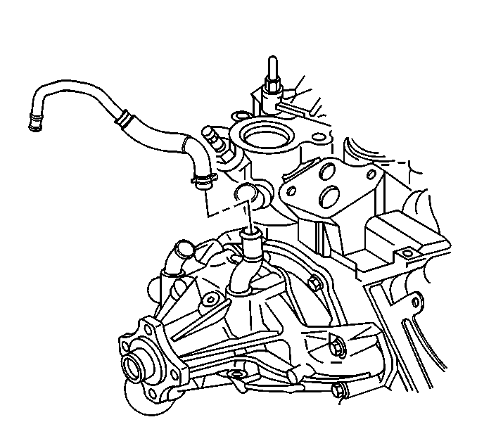
- Remove the heater outlet
hose from the water pump.
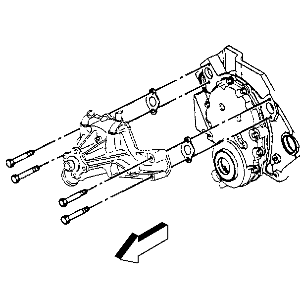
- Remove the water pump
mounting bolts.
- Remove the water pump and the gasket.
- Clean and inspect the sealing surfaces of the engine block.
- Clean the water pump mounting bolts, and inspect the threads for
damage.
Installation Procedure
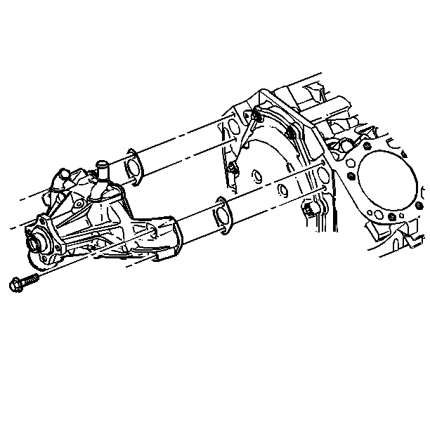
- Install the gasket and
the water coolant pump.
- Apply Teflon Pipe Sealant GM P/N 12346004 or equivalent
thread sealant on the water pump mounting bolts.
Notice: Use the correct fastener in the correct location. Replacement fasteners
must be the correct part number for that application. Fasteners requiring
replacement or fasteners requiring the use of thread locking compound or sealant
are identified in the service procedure. Do not use paints, lubricants, or
corrosion inhibitors on fasteners or fastener joint surfaces unless specified.
These coatings affect fastener torque and joint clamping force and may damage
the fastener. Use the correct tightening sequence and specifications when
installing fasteners in order to avoid damage to parts and systems.
- Install the water
pump mounting bolts.
Tighten
Tighten the bolts to 42 N·m (31 lb ft).

- Install the heater outlet
hose to the water pump.

- Install the by-pass hose
to the water pump.

- Connect the radiator outlet
hose to the water pump.

- Install the water pump
pulley to the water pump.
- Install the water pump pulley mounting bolts.
Tighten
Tighten the bolts to 25 N·m (18 lb ft).
- Install the drive belt in the vehicle. Refer to one of the following
procedures:
- Install the fan clutch in the vehicle. Refer to
Fan Clutch Replacement
.
- Install the upper fan shroud. Refer to
Fan Shroud Replacement
.
- Install the coolant recovery reservoir. Refer to
Coolant Recovery Reservoir Replacement
.

- Install the air intake
duct to the throttle body.
- Install the air cleaner assembly in the vehicle. Refer to one
of the following procedures:
- Connect the battery negative cable to the battery terminal. Refer
to
Battery Negative Cable Disconnection and Connection
in Engine Electrical.
Notice: When adding coolant, use DEX-COOL® coolant. If silicated coolant
is added to the system, premature engine, heater core or radiator corrosion
may result. In addition, the engine coolant will require change sooner-at
50 000 km (30,000 mi) or 24 months.
- Refill the
engine coolant system. Refer to
Cooling System Draining and Filling
.
- Bleed the air from the cooling system.
- Inspect the system for coolant leaks.
Water Pump Replacement 6.5L
Removal Procedure
- Disconnect both negative battery cables from the batteries. Refer
to
Battery Negative Cable Disconnection and Connection
in Engine Electrical.
- Drain the engine cooling system. Refer to
Cooling System Draining and Filling
.
- Remove the air cleaner assembly from the vehicle. Refer to
Air Cleaner Assembly Replacement
in Engine Controls
- 6.5L (L65).
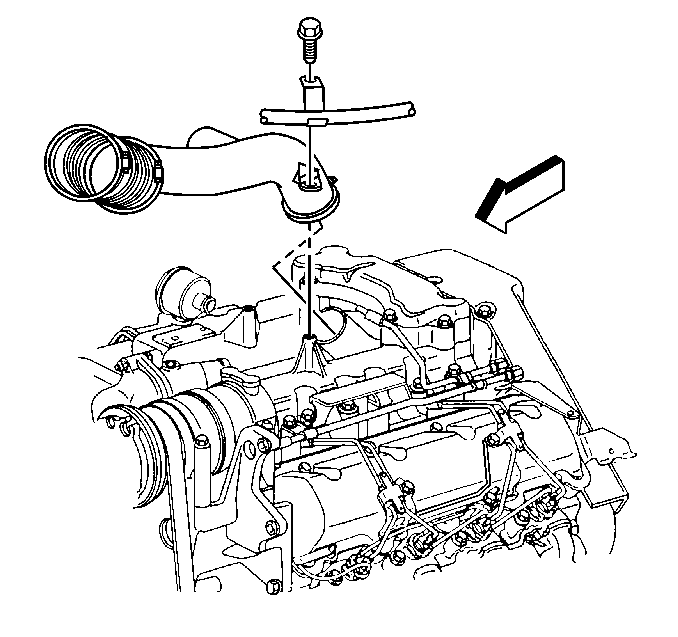
- Remove the air intake
duct from the turbocharger.
- Remove the surge tank from the vehicle. Refer to
Radiator Surge Tank Replacement
.
- Remove the upper fan shroud from the radiator. Refer to
Fan Shroud Replacement
.
- Remove the fan clutch from the water pump pulley. Refer to
Fan Clutch Replacement
.
- Remove the drive belt from the vehicle. Refer to
Drive Belt Replacement
in Engine Mechanical - 6.5L.

- Remove the water pump
pulley mounting bolts.
- Remove the water pump pulley from the water pump.

- Disconnect the radiator
outlet hose from the water pump.
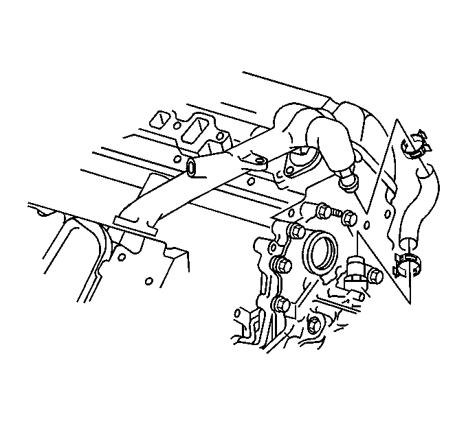
- Disconnect the by-pass
hose from the water pump.
- Remove the generator mounting bracket from the engine block. Refer
to
Generator Bracket Replacement
in
Engine Electrical.
- Remove the engine lift bracket from the engine block. Refer to
Engine Lift Bracket Replacement
in Engine Mechanical
- 6.5L.
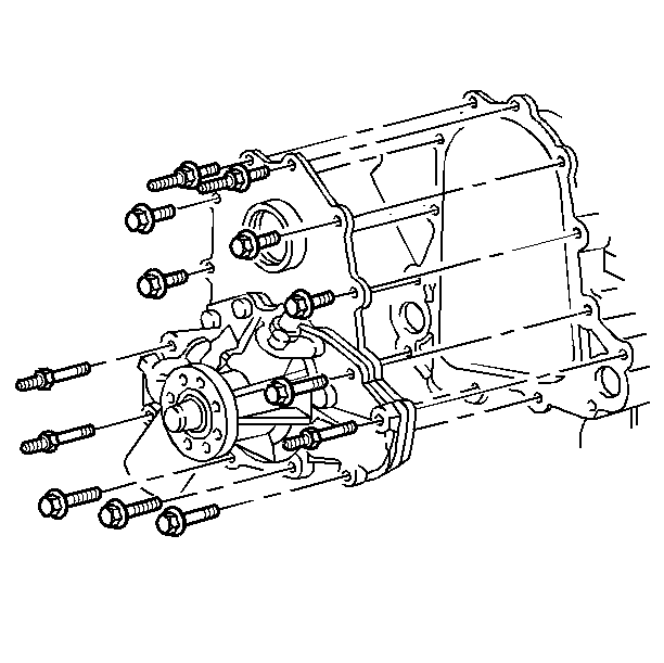
- Remove the water pump
mounting bolts.
- Remove the water pump assembly from the engine front cover.
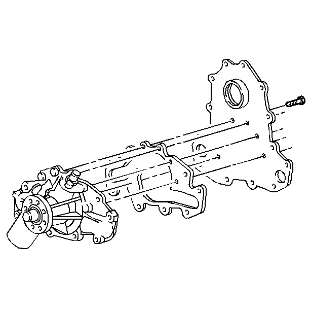
- Remove the bolts from
the back of the water pump backing plate.
- Remove the water pump from the backing plate.
- Remove the gasket from the water pump backing plate.
- Clean and inspect the gasket sealing surfaces of the engine front
cover and water pump backing plate.
- Clean all the water pump mounting bolts.
Installation Procedure

Important: When servicing the water pump assembly, do not apply any sealant to
the water pump gasket. The water pump gasket is manufactured with the proper
amount of sealant printed on it.
- Install the water pump gasket.
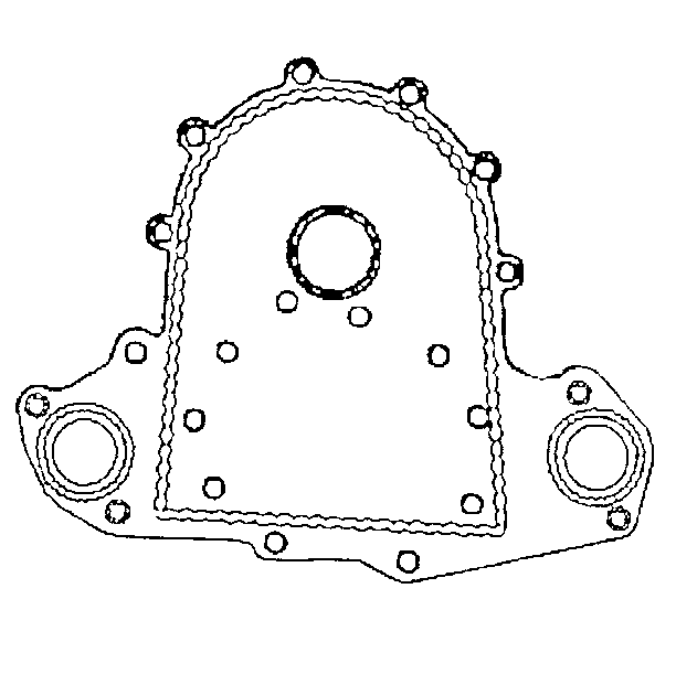
- Apply a bead of anerobic
sealer GM P/N 1052942 or the equivalent to the water pump plate.
- Install the water pump to the backing plate.
- Apply high temperature thread adhesive GM P/N 12345493
or equivalent, to the bolt threads.
Notice: Use the correct fastener in the correct location. Replacement fasteners
must be the correct part number for that application. Fasteners requiring
replacement or fasteners requiring the use of thread locking compound or sealant
are identified in the service procedure. Do not use paints, lubricants, or
corrosion inhibitors on fasteners or fastener joint surfaces unless specified.
These coatings affect fastener torque and joint clamping force and may damage
the fastener. Use the correct tightening sequence and specifications when
installing fasteners in order to avoid damage to parts and systems.
- Install the mounting
bolts behind the water pump plate.
Tighten
Tighten the water pump plate bolts to 28 N·m (20 lb ft).

- Install the water pump
and backing plate to the engine.
The sealer must be wet to the touch when installing the plate.
- Apply Teflon Pipe Sealant GM P/N 123456004 or equivalent
to the thread of the bolts and the studs.
- Install the bolts and the studs.
Tighten
| • | Tighten the water pump to the front cover bolts to 42 N·m
(32 lb ft). |
| • | Tighten the water pump plate to the front cover to 28 N·m
(20 lb ft). |

- Connect the by-pass hose
to the water pump.
- Install the engine lift bracket to the engine block. Refer to
Engine Lift Bracket Replacement
in Engine Mechanical
- 6.5L.
- Install the generator mounting bracket to the engine block. Refer
to
Generator Bracket Replacement
in
Engine Electrical.

- Connect the radiator outlet
hose to the water pump.

- Install the water pump
pulley to the water pump.
- Install the water pump pulley mounting bolts.
Tighten
Tighten the water pump pulley mounting bolts to 25 N·m
(18 lb ft).
- Install the drive belt on the vehicle. Refer to
Drive Belt Replacement
.
- Install the fan clutch to the water pump pulley. Refer to
Fan Clutch Replacement
.
- Install upper radiator shroud on the radiator. Refer to
Fan Shroud Replacement
.
- Install the surge tank in the vehicle. Refer to
Radiator Surge Tank Replacement
.
- Connect the both battery negative cables to the batteries. Refer
to
Battery Negative Cable Disconnection and Connection
in Engine Electrical.
- Refill the engine cooling system. Refer to
Cooling System Draining and Filling
.
- Using the following procedures, bleed the air from the engine
cooling system.
| 21.1. | Remove the cap from the surge tank. |
| 21.2. | Remove the bleed screw (slotted) from the top of the thermostat
housing. |
| 21.3. | Pour coolant into the surge tank, and watch for coolant flowing
from the bleed screw. |
| 21.4. | When a constant flow of coolant is reached, closed the bleed
screw at the top of the thermostat housing. |
| 21.5. | Continue to fill the surge tank to the proper level. |
| 21.6. | Install the cap on the surge tank. |

- Install the air intake
duct to the turbocharger.
- Install the air cleaner assembly in the vehicle. Refer to
Air Cleaner Assembly Replacement
in Engine Controls
- 6.5L (L65).
- Inspect the system for coolant leaks.
Water Pump Replacement 8.1L
Removal Procedure
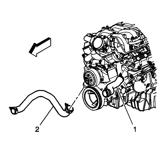
- Drain the cooling system.
Refer to
Cooling System Draining and Filling
.
- Remove the drive belt tensioner. Refer to
Drive Belt Tensioner Replacement
in Engine Mechanical - 8.1L.
- Remove the fan. Refer to
Fan Clutch Replacement
.
- Reposition the outlet hose clamp at the water pump.
- Disconnect the outlet hose (2) from the water pump.
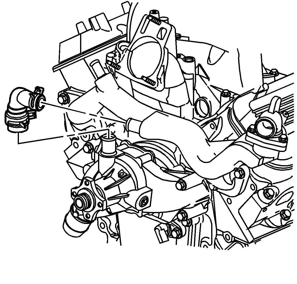
- Reposition the bypass hose clamps at the water pump and crossover.
- Remove the bypass hose.
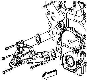
- Remove the water pump
bolts.
- Remove the water pump and gaskets.
Installation Procedure

- Place NEW water pump gaskets
and the water pump into position.
Notice: Use the correct fastener in the correct location. Replacement fasteners
must be the correct part number for that application. Fasteners requiring
replacement or fasteners requiring the use of thread locking compound or sealant
are identified in the service procedure. Do not use paints, lubricants, or
corrosion inhibitors on fasteners or fastener joint surfaces unless specified.
These coatings affect fastener torque and joint clamping force and may damage
the fastener. Use the correct tightening sequence and specifications when
installing fasteners in order to avoid damage to parts and systems.
- Install the water pump bolts.
Tighten
Tighten the water pump bolts to 50 N·m (37 lb ft).

- Install the bypass hose.
- Position the bypass hose clamps at the water pump and crossover.

- Install the outlet hose
(2) to the water pump.
- Position the outlet hose clamp at the water pump.
- Install the fan. Refer to
Fan Clutch Replacement
.
- Install the drive belt tensioner. Refer to
Drive Belt Tensioner Replacement
in Engine Mechanical - 8.1L.
- Fill the cooling system. Refer to
Cooling System Draining and Filling
.


