For 1990-2009 cars only
Tools Required
J 41798 Engine Lift Bracket
Removal Procedure
- Raise the vehicle. Refer to Lifting and Jacking the Vehicle in General Information.
- Disconnect the negative battery cable. Refer to Battery Negative Cable Disconnection and Connection in Engine Electrical.
- Drain the engine oil. Refer to Engine Oil and Oil Filter Replacement .
- Lower the vehicle.
- Remove the hood. Refer to Hood Replacement in Body Front End.
- Evacuate the air conditioning system. Refer to Refrigerant Recovery and Recharging in Heating, Ventilation and Air Conditioning.
- Remove the air cleaner housing assembly. Refer to Air Cleaner Assembly Replacement in Engine Controls.
- Remove the engine sight shield. Refer to Upper Intake Manifold Sight Shield Replacement .
- Drain the cooling system. Refer to Cooling System Draining and Filling in Engine Cooling.
- Remove the upper tie bar. Refer to Front End Upper Tie Bar Replacement in Body Front End.
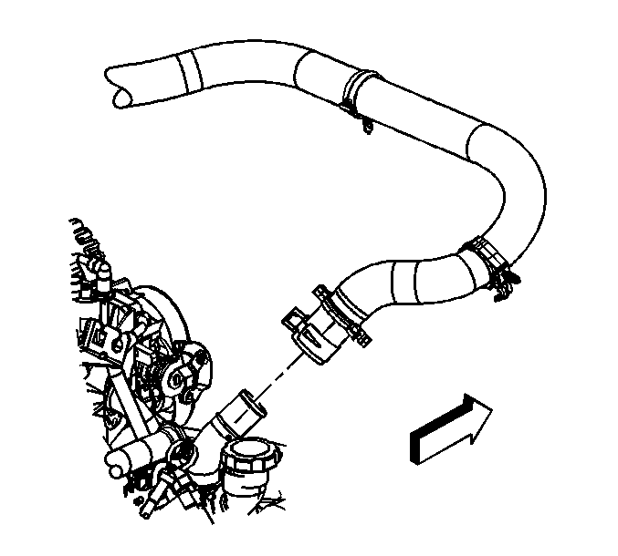
- Remove the upper radiator hose from the water pump outlet.
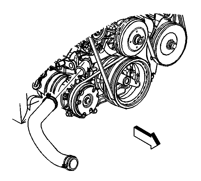
- Remove the lower radiator hose from the thermostat housing.
- Disconnect the electrical from the cooling fan assembly.
- Remove the surge tank hose from the radiator.
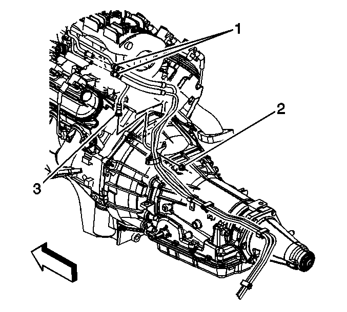
- Remove the transmission cooler lines from the radiator.
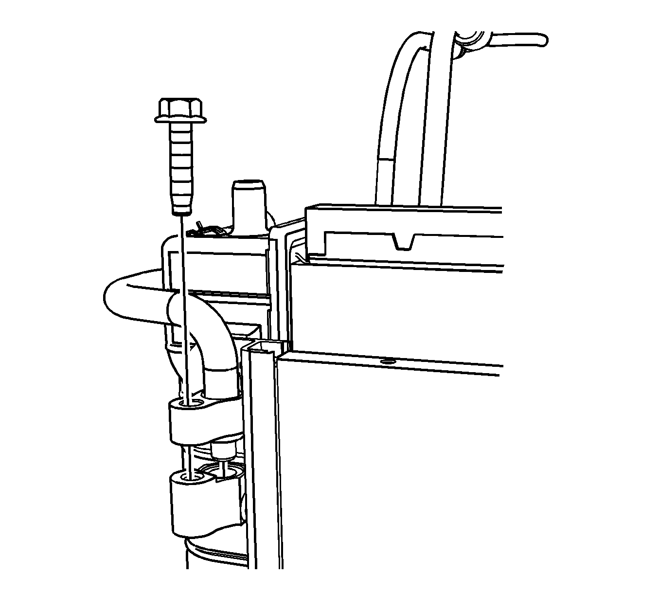
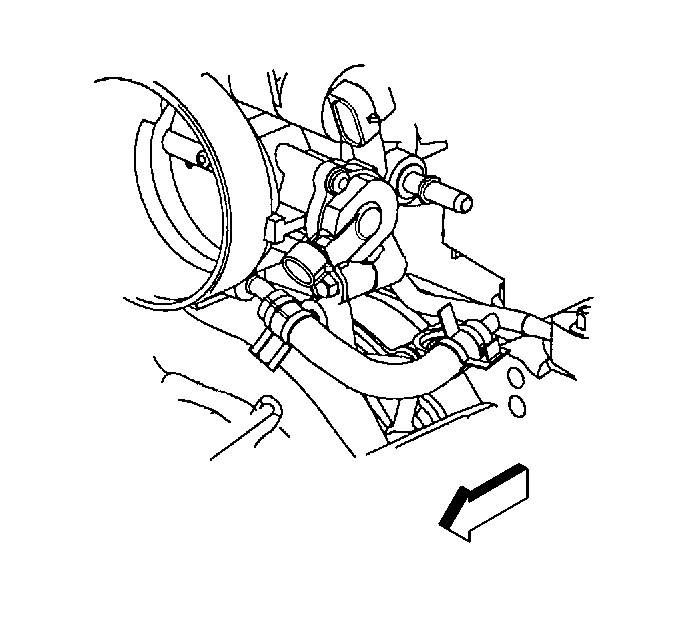
- Remove the bolt (1) retaining the A/C compressor line to the condenser (2).
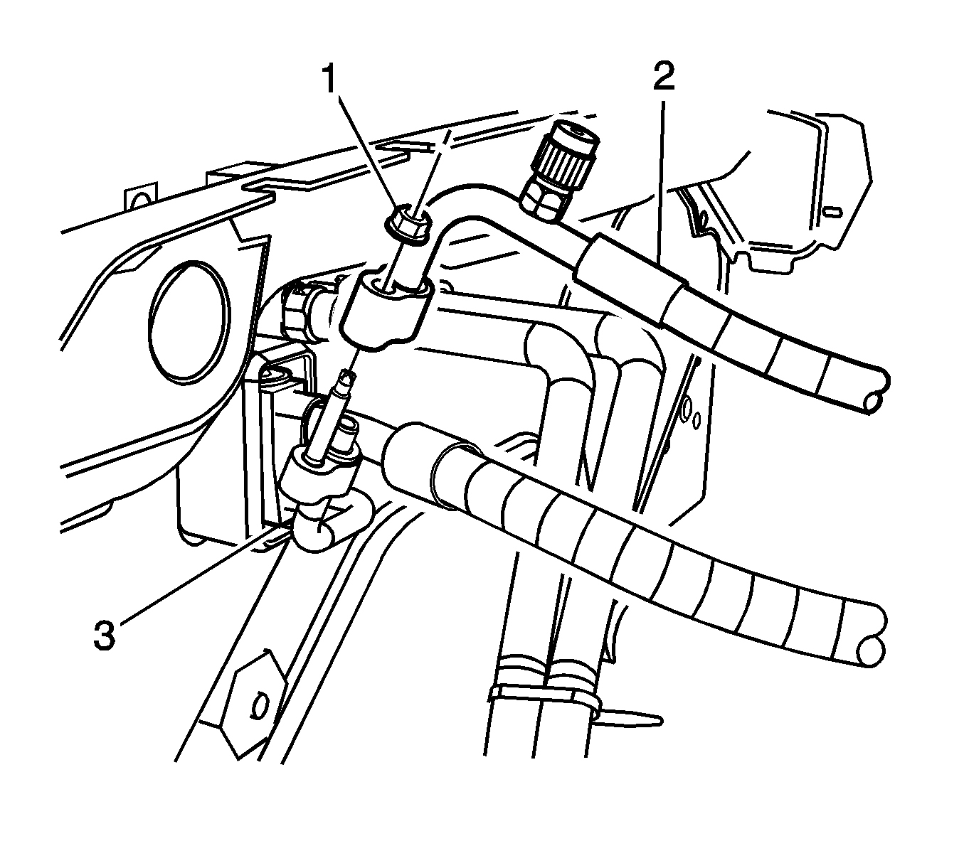
- Remove the nut (1) retaining A/C Compressor line by TXV.
- Remove the condenser/fan/radiator module assembly.
- Remove the brake booster vacuum hose from booster.
- Disconnect the electrical connection from left ignition coil assembly (2).
- Perform the following steps in order to disconnect the left side fuel injector electrical connectors.
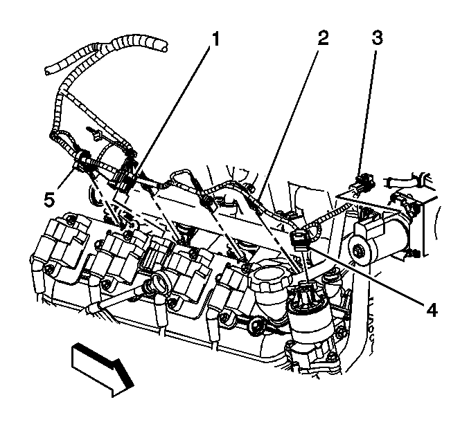
- Remove the nut (2) retaining wiring harness to the intake.
- Disconnect the purge solenoid electrical connector (1).
- Disconnect the generator electrical connector (3).
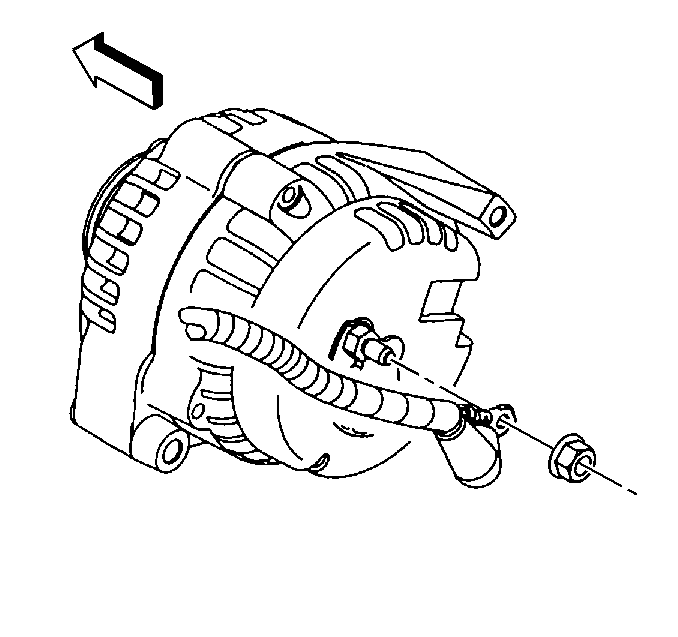
- Disconnect the generator power lead from generator.
- Disconnect the manifold absolute pressure (MAP) sensor (1).
- Disconnect the knock sensor (2) electrical connector.
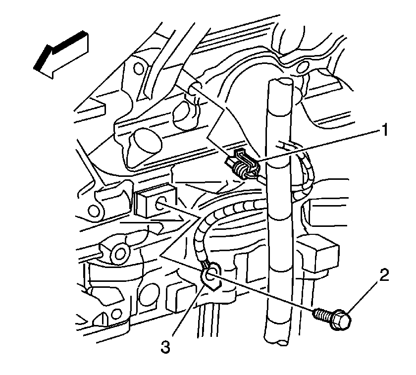
- Disconnect the engine coolant temperature sensor (ECT) (1) and ground wire (3) to block.
- Perform the following steps in order to disconnect the right side fuel injector electrical connectors.
- Disconnect the electronic throttle control (ETC) electrical connection (3).
- Disconnect the electrical from the right side ignition coil assembly (1).
- Disconnect the electrical from the A/C low pressure cut-off switch.
- Disconnect the fuel feed and return pipes (1) from the fuel rail.
- Reposition the upper engine wiring harness aside.
- Reposition the clamp and remove the coolant hose from the throttle body.
- Remove the surge tank coolant hose from throttle body.
- Remove the inlet and outlet heater hoses from the thermostat housing. Refer to Heater Inlet Hose Replacement and Heater Outlet Hose Replacement in Heating, Ventilation and Air Conditioning.
- Remove the heater hoses from the heater core.
- Remove the surge tank assembly from the vehicle. Refer to Radiator Surge Tank Replacement in Engine Cooling.
- Remove the intake assembly. Refer to Intake Manifold Replacement .
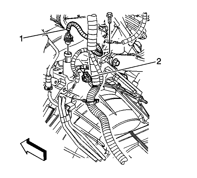
- Disconnect the electrical connectors from the oil pressure sensor (1) and the camshaft position (CMP) sensor (2).
- Remove the compressor hose assembly. Refer to Compressor Hose Assembly Replacement in Heating, Ventilation and Air Conditioning.
- Remove the nut retaining engine ground to the frame and remove the ground wire.
- Remove the PCM and the mounting bracket. Refer to Powertrain Control Module Replacement in Engine Controls.
- Remove the accessory drive belt. Refer to Drive Belt Replacement - Accessory .
- Remove the power steering pump from the bracket and set aside. Refer to Power Steering Pump Replacement in Power Steering System.
- Raise the vehicle.
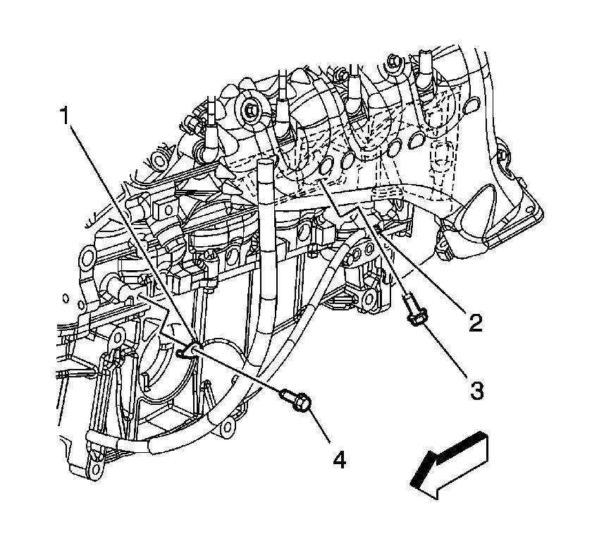
- Remove the bolts (3, 4) and the ground wires (1, 2) from the block.
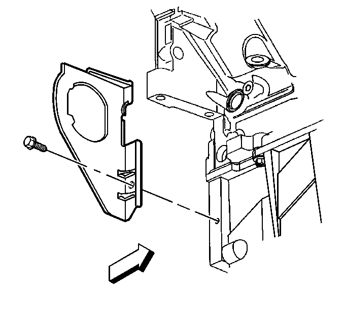
- Remove the left side flywheel cover.
- Remove the wiring harness from the wire looms on the front of the oil pan.
- Disconnect the oil level sensor.
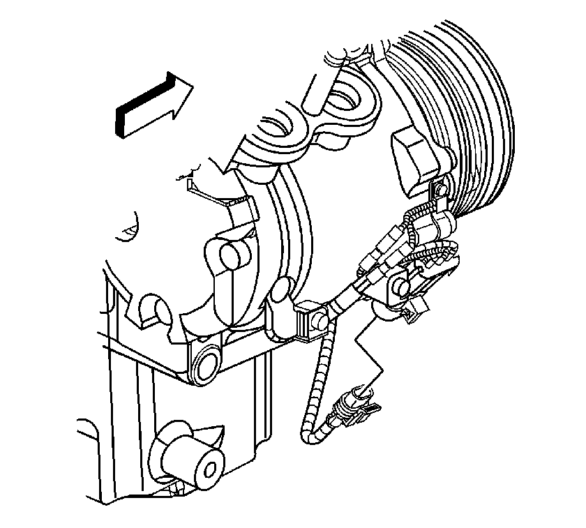
- Disconnect the electrical from the A/C compressor.
- Remove the right side flywheel shield.
- Remove the starter. Refer to Starter Motor Replacement in Engine Electrical.
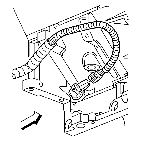
- Disconnect the crankshaft position (CKP) sensor.
- Remove the transmission assembly. Refer to Transmission Replacement in Automatic Transmission - 4L60-E/4L65-E.
- Remove the wire harness from the wire loom on the rear of the engine.
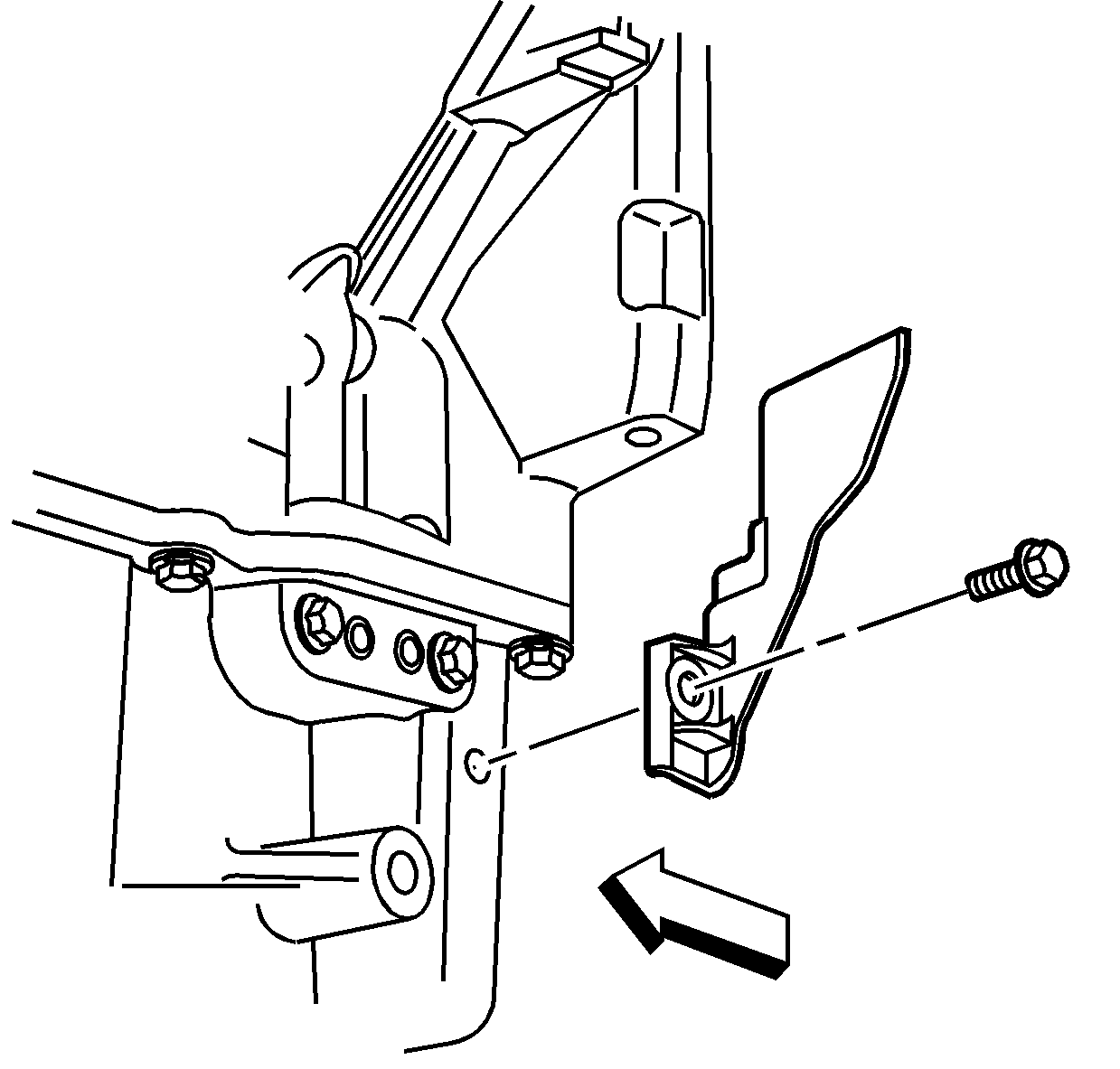
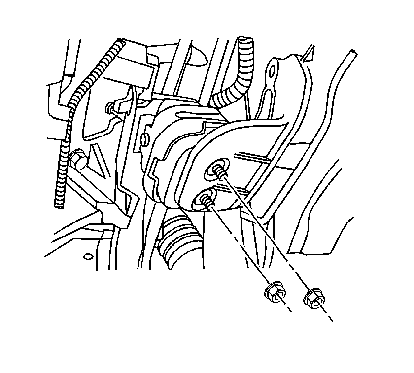
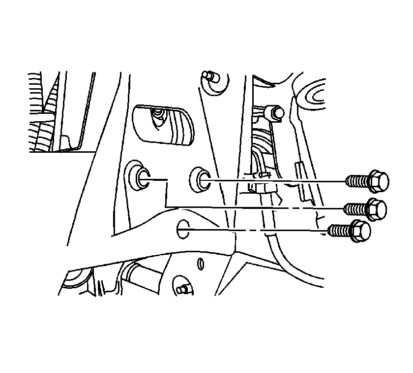
- Remove the left lower motor mount retaining nuts.
- Lower the vehicle.
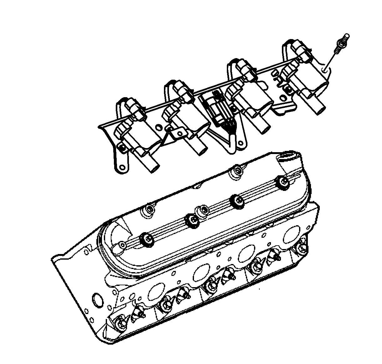
- Remove the coil assemblies from the rocker arm covers.
- Disconnect the EVAP purge solenoid.
- Install the J 41798 to the engine.
- Remove the right side shock assembly. Refer to Shock Absorber and Spring Assembly Replacement in Front Suspension.
- Remove the frame motor mount bolts.
- Install the engine hoist to the engine.
- Remove the engine from the vehicle.
- Install the engine to the stand.
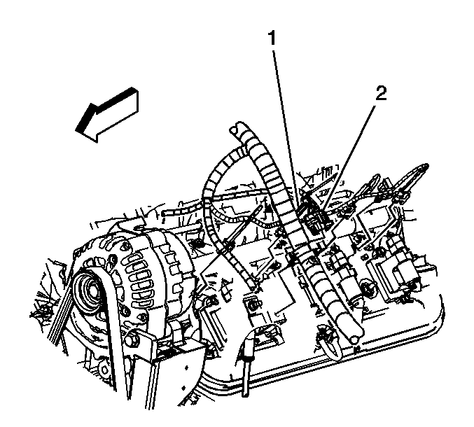
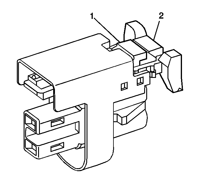
| 21.1. | Mark the connectors to their corresponding injectors to ensure correct reassembly. |
| 21.2. | Pull the connector position assurance (CPA) retainer (2) on the connector up 1 click. |
| 21.3. | Push the tab (1) on the connector in. |
| 21.4. | Disconnect the fuel injector electrical connector. |
| 21.5. | Repeat the steps for each injector electrical connector. |
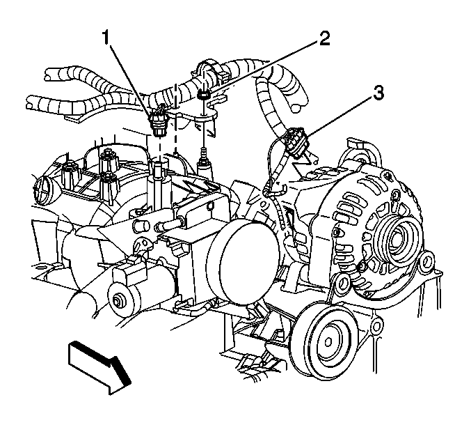
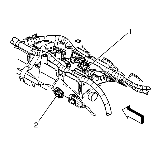

| 29.1. | Mark the connectors to their corresponding injectors to ensure correct reassembly. |
| 29.2. | Pull the connector position assurance (CPA) retainer (2) on the connector up 1 click. |
| 29.3. | Push the tab (1) on the connector in. |
| 29.4. | Disconnect the fuel injector electrical connector. |
| 29.5. | Repeat the steps for each injector electrical connector. |
Installation Procedure
- Remove the engine from the stand.
- Install the engine to the vehicle.
- Remove the engine hoist from the engine.
- Install the frame motor mount bolts.
- Install the right side shock assembly. Refer to Shock Absorber and Spring Assembly Replacement in Front Suspension.
- Remove the J 41798 from the engine.
- Connect the EVAP purge solenoid.
- Install the coil assemblies to the rocker arm covers.
- Raise the vehicle.
- Install the left lower motor mount retaining nuts.
- Install wire harness to wire loom on rear of engine.
- Install transmission assembly. Refer to Transmission Replacement in Automatic Transmission - 4L60-E/4L65-E.
- Connect crankshaft position (CKP) sensor.
- Install the starter. Refer to Starter Motor Replacement in Engine Electrical.
- Install the right side flywheel shield.
- Connect the electrical to the A/C compressor.
- Connect the oil level sensor.
- Install the wiring harness to the wire looms on the front of the oil pan.
- Install the left side flywheel cover.
- Install the bolts (3, 4) and the ground wires (1, 2) to the block.
- Raise the vehicle.
- Install the power steering pump to bracket. Refer to Power Steering Pump Replacement in Power Steering System.
- Install the accessory drive belt. Refer to Drive Belt Replacement - Accessory .
- Install the PCM mounting bracket and the PCM. Refer to Powertrain Control Module Replacement in Engine Controls.
- Install the nut to retain the engine ground to the frame.
- Install the compressor hose assembly. Refer to Compressor Hose Assembly Replacement in Heating, Ventilation and Air Conditioning.
- Connect the electrical connectors to the oil pressure sensor (1) and the camshaft position (CMP) sensor (2).
- Install the intake assembly. Refer to Intake Manifold Replacement .
- Install the surge tank assembly to vehicle. Refer to Radiator Surge Tank Replacement in Engine Cooling.
- Install the heater hoses to heater core.
- Install the inlet and outlet heater hoses to the thermostat housing. Refer to Heater Inlet Hose Replacement and Heater Outlet Hose Replacement in Heating, Ventilation and Air Conditioning.
- Install the surge tank coolant hose to the throttle body.
- Install the coolant hose to the throttle body.
- Position the upper engine wiring harness.
- Connect the fuel feed and return pipes (1) to the fuel rail.
- Connect the electrical to the A/C low pressure cut-off switch.
- Connect the electrical to the right side ignition coil assembly (1).
- Connect the ETC electrical connection (3).
- Connect the right side fuel injector electrical connectors.
- Connect the ECT sensor (1) and the ground wire (3) to the block.
- Connect the knock sensor (2) electrical connector.
- Connect the MAP sensor (1).
- Connect the generator power lead to the generator.
- Install the nut (2) retaining the wiring harness to the intake.
- Connect the purge solenoid electrical connector (1).
- Connect the generator electrical connector (3).
- Connect the left side fuel injector electrical connectors.
- Connect the electrical connection to the left ignition coil assembly (2).
- Install the brake booster vacuum hose to the booster.
- Install the condenser/fan/radiator module assembly.
- Install the nut (1) retaining the A/C compressor line (2) by TXV.
- Install the bolt (1) retaining the A/C compressor line to the condenser (2).
- Install the transmission cooler lines to the radiator.
- Install the surge tank hose to the radiator.
- Connect the electrical to the cooling fan assembly.
- Install the lower radiator hose to the thermostat housing.
- Install the upper radiator hose to the water pump outlet.
- Install the upper tie bar. Refer to Front End Upper Tie Bar Replacement in Body Front End.
- Fill the cooling system. Refer to Cooling System Draining and Filling in Engine Cooling.
- Fill the engine oil. Refer to Engine Oil and Oil Filter Replacement .
- Install the hood. Refer to Hood Replacement in Body Front End.
- Recharge the air conditioning system. Refer to Refrigerant Recovery and Recharging in Heating, Ventilation and Air Conditioning.
- Install the air cleaner housing assembly. Refer to Air Cleaner Assembly Replacement in Engine Controls.
- Install the engine sight shield. Refer to Upper Intake Manifold Sight Shield Replacement .
- Raise the vehicle.
- Connect the negative battery cable. Refer to Battery Negative Cable Disconnection and Connection in Engine Electrical.
- Lower the vehicle. Refer to Lifting and Jacking the Vehicle in General Information.

Notice: Refer to Fastener Notice in the Preface section.
Tighten
Tighten the bolts to 100 N·m (74 lb ft).


Tighten
Tighten nuts to 50 N·m (37 lb ft).


Tighten
Tighten bolt to 10 N·m (89 lb in).


Tighten
Tighten the bolt to 10 N·m (89 lb in).

Tighten
Tighten the bolts to 16 N·m (12 lb ft).

Tighten
Tighten the nut to 25 N·m (18 lb ft).


Tighten
Tighten the bolt to 9 N·m (80 lb in).

Tighten
Tighten the nut to 10 N·m (89 lb in).


Tighten
Tighten the nut to 20 N·m (15 lb ft).

Tighten
Tighten the bolt to 16 N·m (12 lb ft).

