Removal Procedure
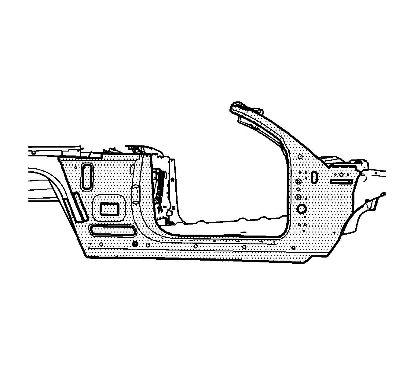
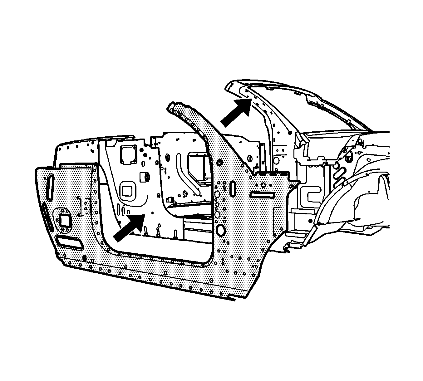
The replacement outer body side is serviced as a complete assembly. It is necessary to remove and replace the upper fender rails and the outer wheel house panel in order to replace the outer body side panel.
The upper fender rails and the outer wheelhouse panels are not included and must be ordered separately.
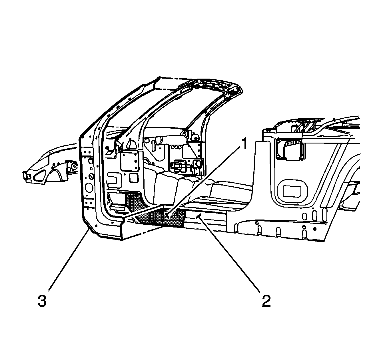
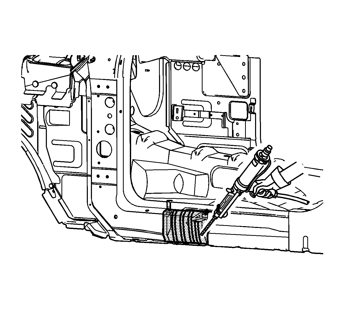
Important: Structural foam (1) is located between the inner rocker (2) and the inner hinge pillar reinforcements (3) on both the right and the left side of the vehicle. Precast structural foam replacement blocks are available if necessary, and can be ordered separately.
Failure to replace any damaged structure foam reinforcement as described could compromise the structural integrity of the vehicle. Refer to Structure Foam Replacement .- Disable the SIR system. Refer to SIR Disabling and Enabling in SIR.
- Disconnect the negative battery cable. Refer to Battery Negative Cable Disconnection and Connection in Engine Electrical.
- Remove all related panels and components including the upper fender rail. Refer to Front Fender Upper Rail Replacement or to Rear Outer Wheelhouse Replacement .
- Repair as much of the damage as possible to factory specifications. Refer to Door Opening and Roof Stowage Dimensions in Dimensions - Body .
- Note the location and remove the sealers and anti-corrosion materials from the repair area, as necessary. Refer to Anti-Corrosion Treatment and Repair in Paint and Coatings.
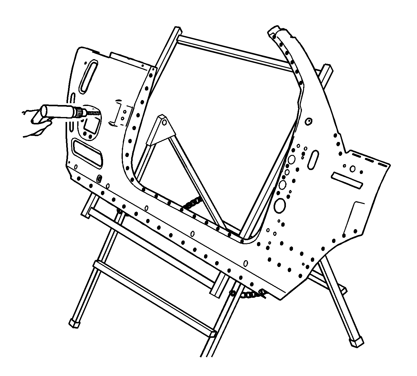
- Locate and drill out all factory welds on the outer body side. Note the number and location of the welds for installation of the outer body side service part.
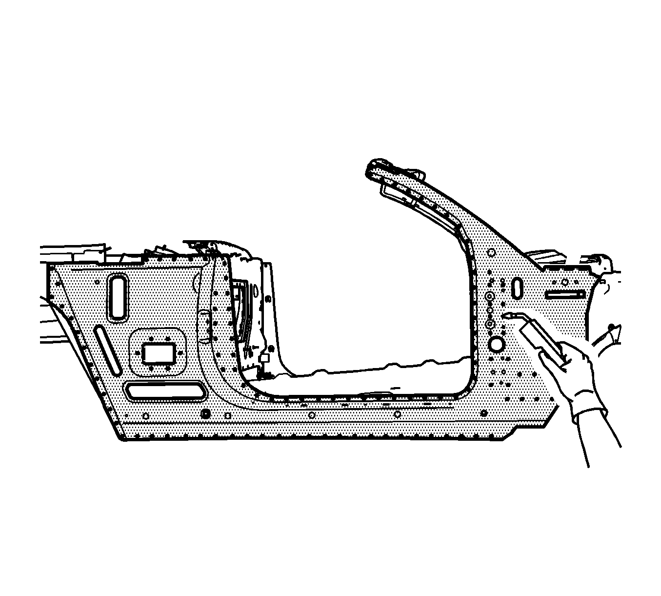
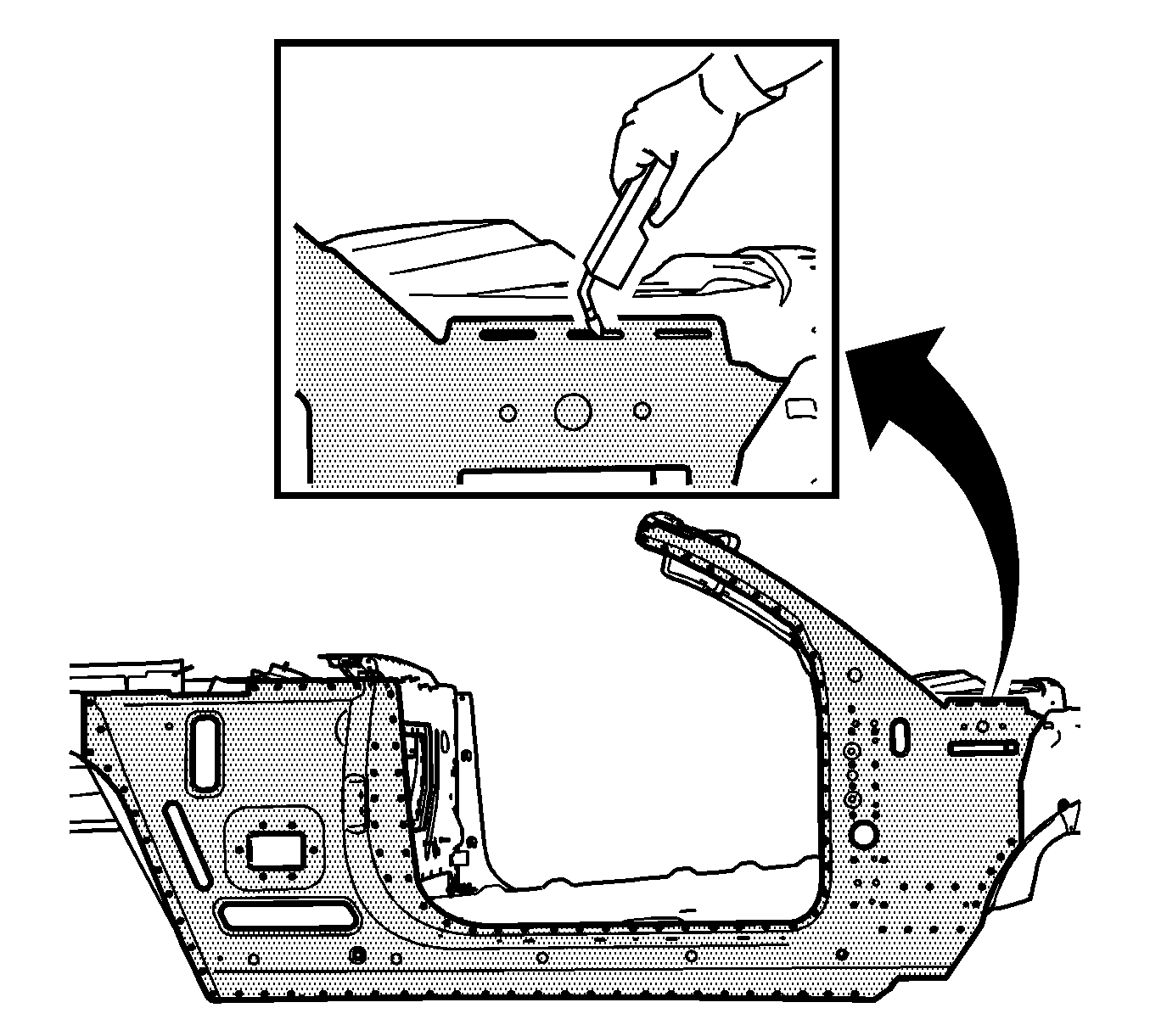
- On the passenger side only, use a grinder or equivalent to remove the MIG welds as shown.
- Verify the existence of structural weld-through adhesive. Refer to Structure Adhesive Identification . If necessary use a chisel to separate the body side panel from the adjacent panels.
- Remove the damaged outer body side panel.
Caution: Refer to Approved Equipment for Collision Repair Caution in the Preface section.
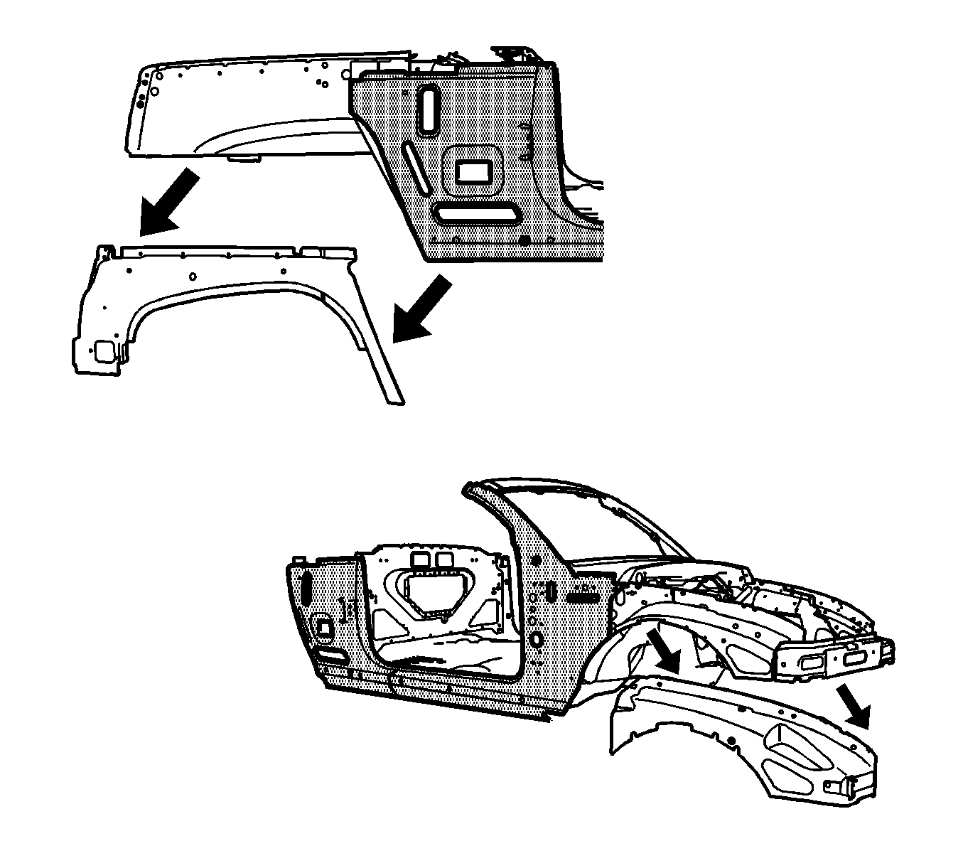
Important: When replacing the outer body side assembly, it is necessary to remove the upper fender rail and the outer wheel house panel. Depending on the extent of the damage, you may section the outer wheel house panel in the designated area, or replace the entire outer wheel house.
Caution: Refer to Foam Sound Deadeners Caution in the Preface section.
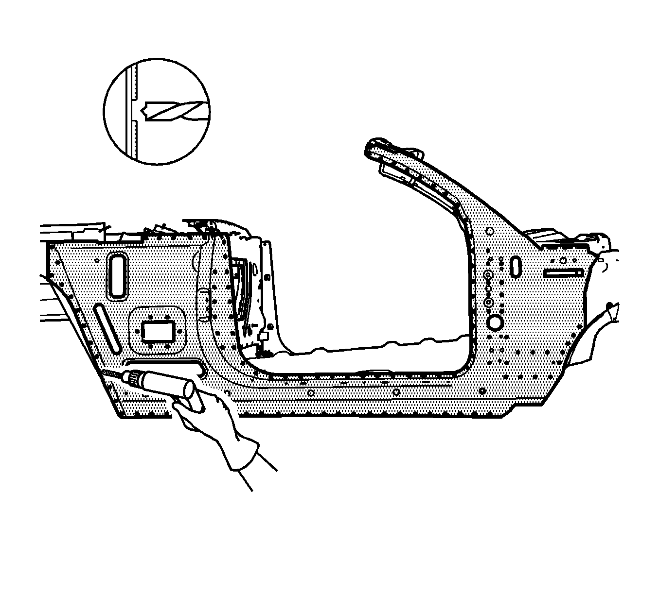
Important: Do NOT damage the inner panels or the structural foam reinforcement block.
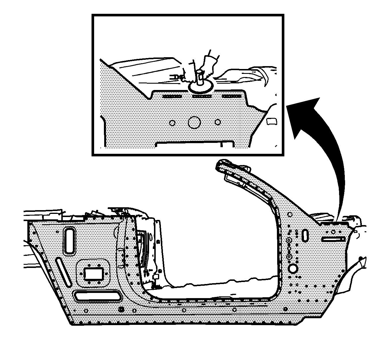
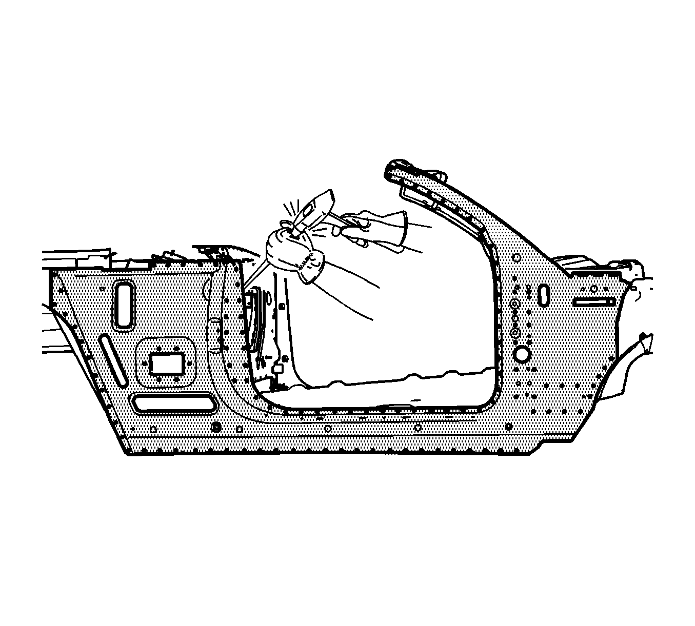
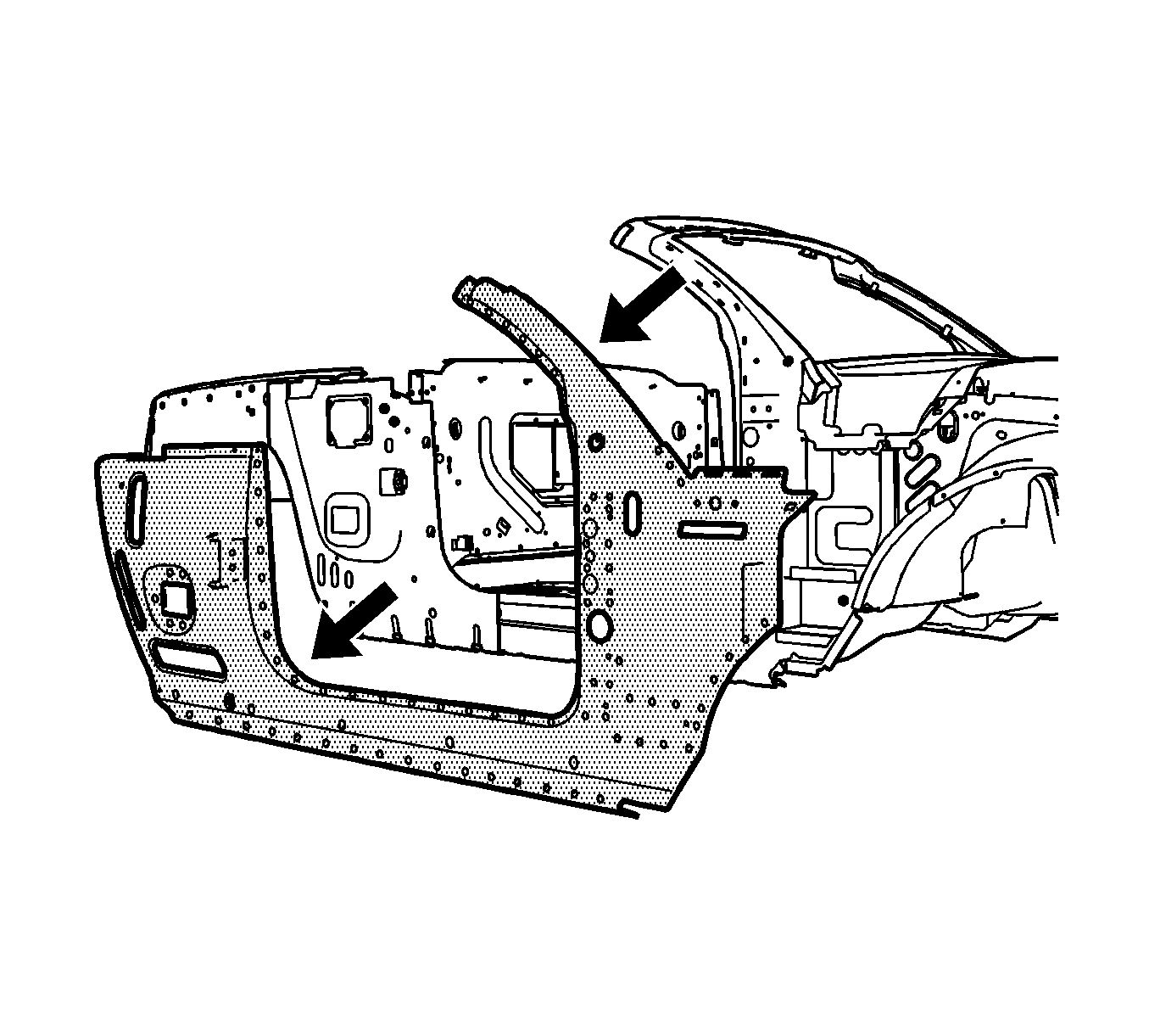
Important: Do NOT damage the structural foam reinforcement block when you remove the outer body side panel.
Installation Procedure
- Drill 8 mm (5/16 in) plug weld holes in the service part as necessary in the locations noted on the original panel.
- Replace the structural adhesive with an additional plug weld between existing plug welds where necessary.
- Prepare all mating surfaces as necessary.
- Apply 3M® Weld-Thru Coating P/N 05916 or equivalent to all mating surfaces.
- Inspect the structural foam for damage and replace the foam if necessary. Refer to Structure Foam Replacement .
- Position the outer body side. Refer to Door Opening and Roof Stowage in Dimensions - Body .
- Plug weld accordingly.
- On the passenger side, continuous MIG weld the 3 slots as shown.
- Install all related panels including the upper fender rail Refer to Front Fender Upper Rail Replacement or to Front Fender Upper Rail Sectioning or to Rear Outer Wheelhouse Replacement .
- Clean and prepare all welded surfaces.
- Apply the sealers and the anti-corrosion materials to the repair area, as necessary. Refer to Anti-Corrosion Treatment and Repair in Paint and Coatings.
- Paint the repair area. Refer to Basecoat/Clearcoat Paint Systems in Paint and Coatings.
- Install all related components.
- Connect the negative battery cable. Refer to Battery Negative Cable Disconnection and Connection in Engine Electrical.
- Enable the SIR system. Refer to SIR Disabling and Enabling in SIR.
