For 1990-2009 cars only
Tools Required
KM-507-C Ball Joint Remover
Removal Procedure
- Raise and suitably support the vehicle. Refer to Lifting and Jacking the Vehicle .
- Remove the wheels. Refer to Tire and Wheel Removal and Installation .
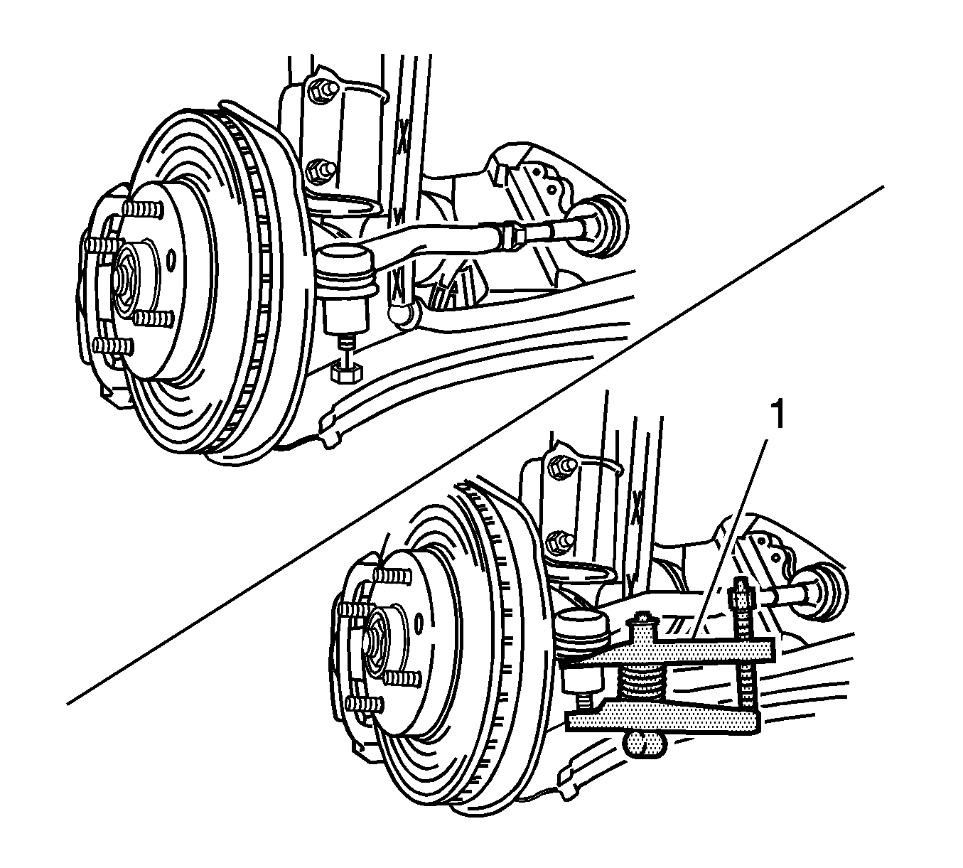
- Remove the outer tie rod nuts and disconnect the tie rod ends from the knuckle using the KM-507-C (1). Refer to Rack and Pinion Outer Tie Rod End Replacement .
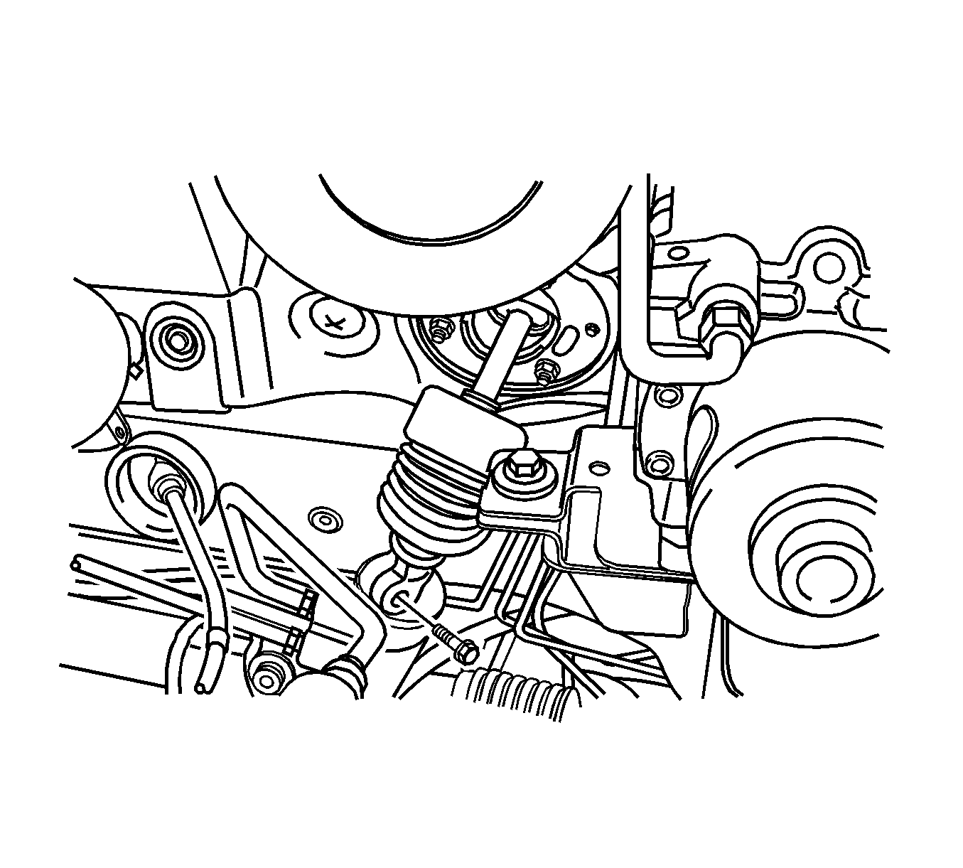
- Remove the lower pinch bolt from the intermediate shaft. Refer to Intermediate Steering Shaft Replacement .
- Remove the return line bracket bolt from the crossmember.
- Disconnect the return line pipe from the power steering gear outlet. Place a drain pan under the steering gear to catch the power steering fluid.
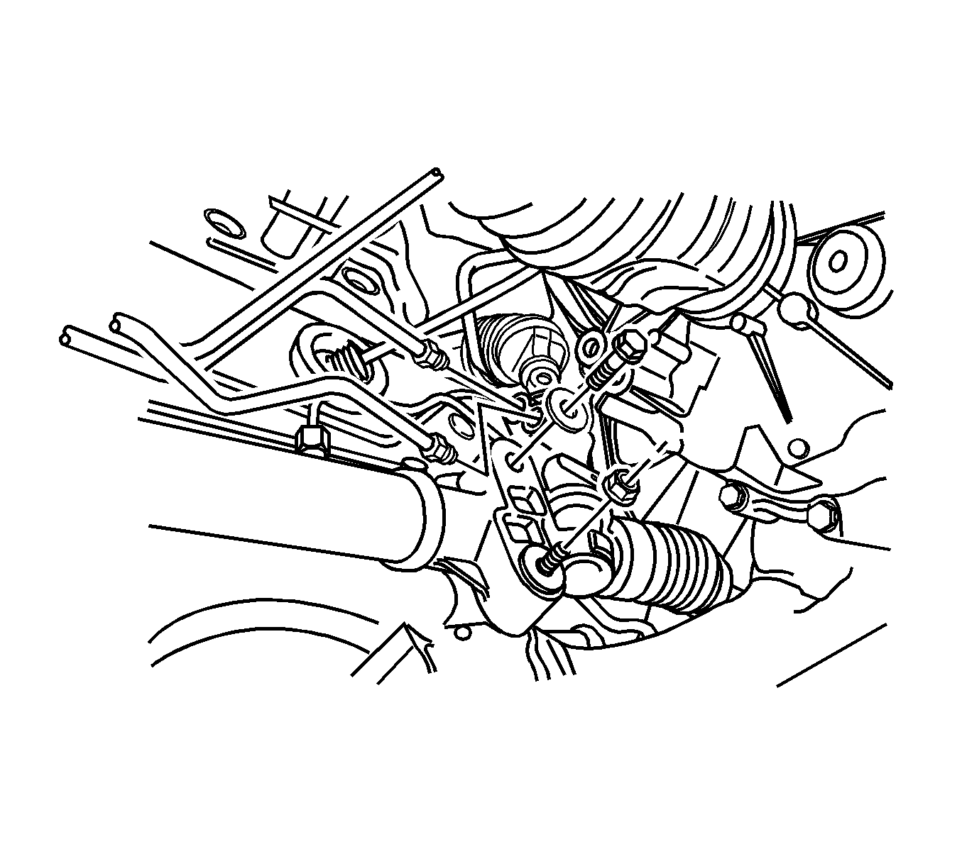
- Disconnect the pressure line pipe from the power steering gear inlet.
- Remove the rack and pinion assembly mounting bolt and nut.
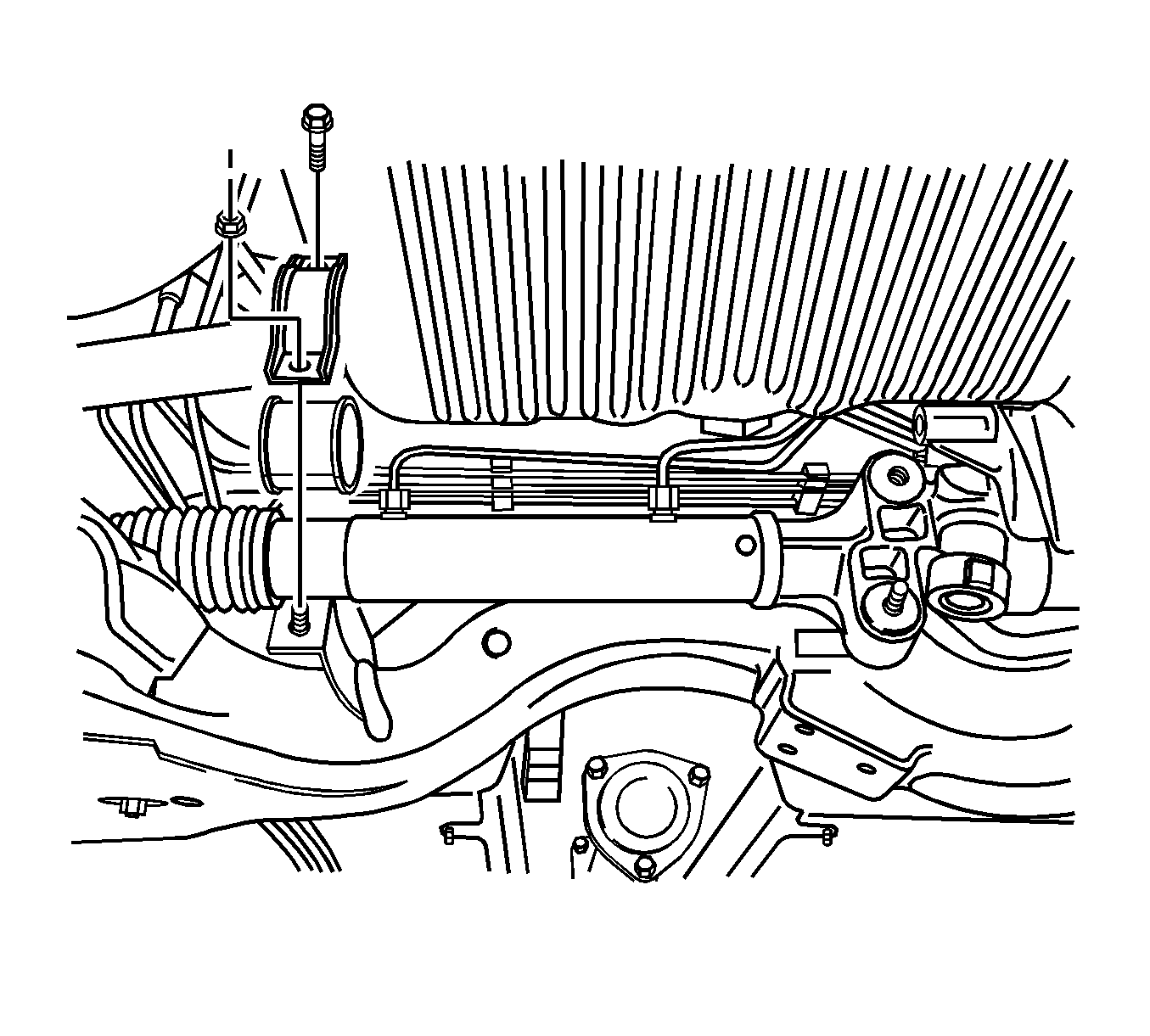
- Remove the rack and pinion assembly U-clamp mounting bolt and nut.
- Remove the U-clamp and the bushing.
- Remove the rack and pinion assembly.
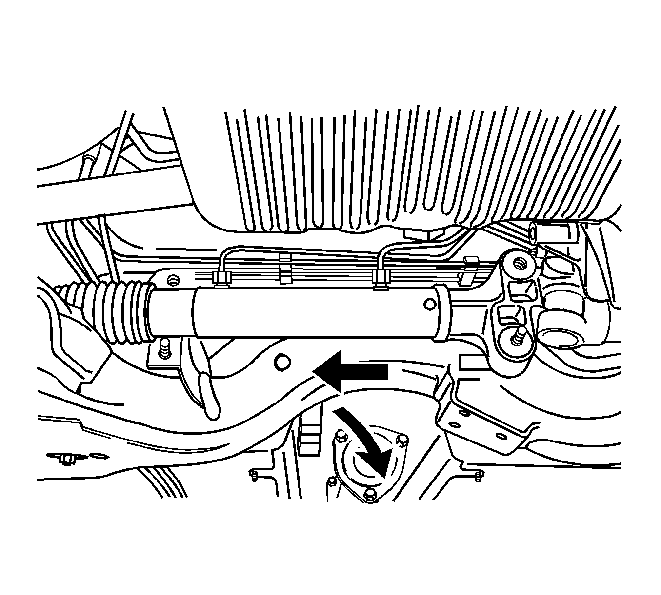
Installation Procedure
- Install the rack and pinion assembly.
- Install the U-clamp and bushing.
- Install the rack and pinion assembly U-clamp mounting bolt and nut.
- Install the rack and pinion assembly mounting bolt and nut.
- Connect the pressure line pipe to the power steering gear inlet.
- Connect the return line pipe to the power steering gear outlet.
- Install the return line bracket bolt to the crossmember.
- Install the lower pinch bolt to the intermediate shaft.
- Install the tie rod ends to the knuckle.
- Install the outer tie rod nuts.
- Install the wheels. Refer to Tire and Wheel Removal and Installation .
- Add power steering fluid to the MAX level.
- Inspect the vehicle. Refer to Preliminary Alignment Inspection and to Straight Ahead Inspection .
- Measure the wheel alignment.
- If necessary, adjust the front toe. Refer to Front Toe Adjustment .


Notice: Refer to Fastener Notice in the Preface section.
Tighten
Tighten the bolt and nut to 60 N·m (44 lb ft).

Tighten
Tighten the bolt and nut to 60 N·m (44 lb ft).
Tighten
Tighten the nut to 28 N·m (21 lb ft).
Tighten
Tighten the nut to 28 N·m (21 lb ft).

Tighten
Tighten the bolt to 8 N·m (6 lb ft).
Tighten
Tighten the bolt to 26 N·m (19 lb ft).
Tighten
Tighten the nuts to 50 N·m (37 lb ft).
