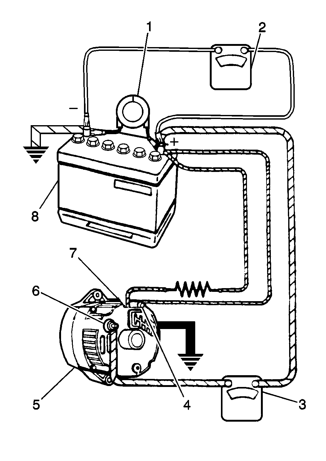
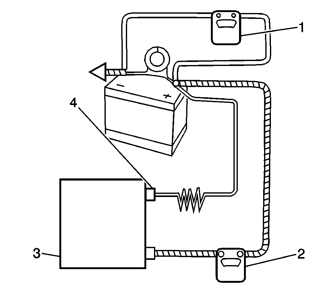
Charging System Check 21-SI
Tools Required
| • | J 39200 Digital Multimeter |
| • | J 35590 Inductive Current Clamp |
Using the Digital Multimeter:
- Disconnect the negative battery cable. Refer to Battery Cable Replacement .
- Connect an ammeter in series between the BAT terminal of the generator and the output lead.
- Connect the negative battery cable. Refer to Battery Cable Replacement .
- Start the engine.
- Turn ON the following components:
- Connect a carbon pile across the battery.
- Operate the engine at 2500 RPM.
- Adjust the carbon pile as necessary in order to obtain the maximum current output.
- If the ampere output is within 10 amperes of the rated output stamped on the generator frame, the generator functions properly.
- If the ampere output is not within 10 amperes of the rated output stamped on the generator frame, repair the generator. Refer to Generator Overhaul
Caution: Unless directed otherwise, the ignition and start switch must be in the OFF or LOCK position, and all electrical loads must be OFF before servicing any electrical component. Disconnect the negative battery cable to prevent an electrical spark should a tool or equipment come in contact with an exposed electrical terminal. Failure to follow these precautions may result in personal injury and/or damage to the vehicle or its components.
| • | The radio |
| • | The windshield wipers |
| • | The headlamps (high beam) |
| • | The blower motor (high speed) |

Important: Residual magnetism in the rotor causes the initial voltage buildup. Increase the engine speed as necessary in order to obtain the maximum current output.
Using the Inductive Current Clamp:
- Install the J 35590 .
- Start the engine.
- Turn ON the following components:
- Connect a carbon pile across the battery.
- Operate the engine at 2500 RPM.
- Adjust the carbon pile as necessary in order to obtain the maximum current output.
- If the ampere output is within 10 amperes of the rated output stamped on the generator frame, the generator functions properly.
- If the ampere output is not within 10 amperes of the rated output stamped on the generator frame, repair the generator. Refer to Generator Overhaul .
| • | The radio |
| • | The windshield wipers |
| • | The headlamps (high beam) |
| • | The blower motor (high speed) |
Important: Residual magnetism in the rotor causes the initial voltage buildup. Increase the engine speed as necessary in order to obtain the maximum current output.
Charging System Check CS-144
Tools Required
| • | J 39200 Digital Multimeter |
| • | J 35590 Inductive Current Clamp |
- Disconnect the wire harness from the generator.
- Set the J 39200 to the DC voltage scale.
- Connect the J 39200 from ground to the L terminal in the wiring harness.
- Verify that the voltage is B+.
- Correct any faults as necessary.
- Connect the electrical connector to the generator.
- Turn OFF all of the accessories.
- Run the engine at 2500 RPM.
- Measure the voltage across the battery.
- Disconnect the negative battery cable. Refer to Battery Cable Replacement .
- If you use the J 39200 , connect an ammeter in series between the BAT terminal of the generator and the output lead. Ensure that the ammeter is able to measure 115 amps of current.
- If you use the J 35590 , install the J 35590 around the generator output lead.
- Connect the negative battery cable. Refer to Negative Battery Cable in Battery Cable Replacement .
- Connect a carbon pile across the battery.
- Start the engine.
- Run the engine at 2500 RPM.
- Turn ON the accessories.
- Load the battery using a carbon pile in order to obtain maximum amperage.
- Maintain the voltage at 13 volts or above.
- If the output is within 15 amperes of the rated output, the generator is working properly.
- If the output is not within 15 amperes of the rated output, replace the generator.
A reading other than B+ indicates one of the following faults between the terminal and the battery:
| • | An open circuit |
| • | A high resistance |
| • | A grounded circuit |
If the voltage is above 16 volts, replace the generator.
Caution: Unless directed otherwise, the ignition and start switch must be in the OFF or LOCK position, and all electrical loads must be OFF before servicing any electrical component. Disconnect the negative battery cable to prevent an electrical spark should a tool or equipment come in contact with an exposed electrical terminal. Failure to follow these precautions may result in personal injury and/or damage to the vehicle or its components.

Charging System Check SCT
Step | Action | Normal Result(s) | Abnormal Result(s)* | ||||||
|---|---|---|---|---|---|---|---|---|---|
1 | Move the ignition switch from the OFF position to the RUN position. | Battery indicator lamp turns ON, voltmeter gage reads between 12-14 volts. | Refer to:
| ||||||
2 | Move the Ignition Switch to the START position and then release. | The engine starts, the voltage gage reads between 13-16 volts, the battery indicator lamp turns OFF. | Refer to: | ||||||
3 | Run the engine at idle while observing the voltmeter gage and the battery indicator lamp. | Voltmeter gage holds steady between 13-16 volts and the battery indicator lamp is OFF. | Refer to Charging System Check . | ||||||
4 |
| Voltmeter gage holds steady between 13-16 volts and the battery indicator lamp is OFF. | Refer to Charging System Check . | ||||||
* Refer to the appropriate symptom diagnostic table for the applicable abnormal result. | |||||||||
