Removal Procedure

- Set the parking brakes.
- Block the vehicle rear wheels.
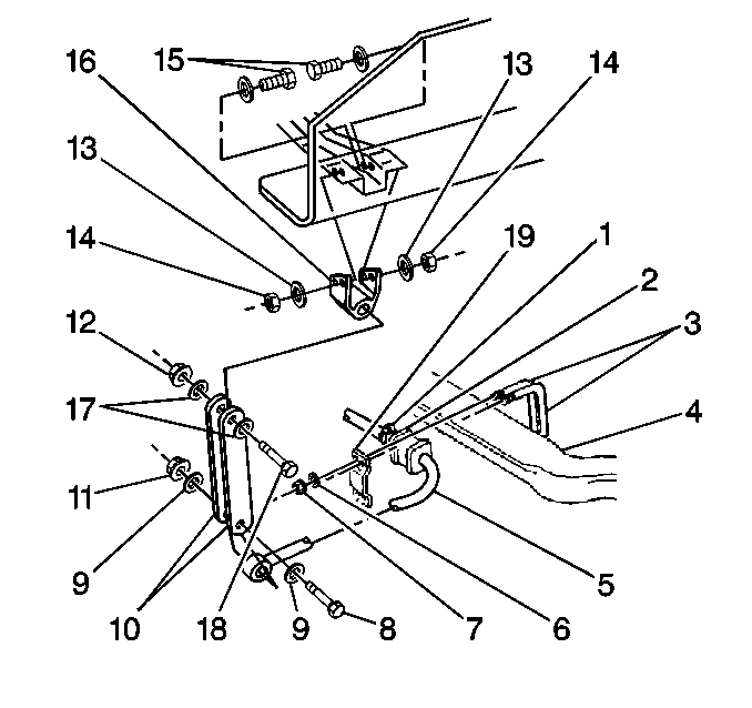
- Remove the stabilizer shaft (5) from the axle (4)
if equipped. Refer to
Stabilizer Shaft Replacement
.
- Raise the vehicle frame until the front tires clear the floor.
Notice: Do not use the front crossmember to support the vehicle or the crossmember
may buckle.
- Support
the frame using suitable safety stands.

- Remove the wheels, the
hubs, and the bearings as needed. Refer to
Front Wheel Hub, Bearing, and Seal Replacement
.
- Remove the following components from the lower brackets (7):
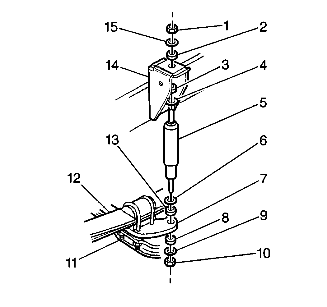
- Remove the shock absorbers (5) from the lower brackets (7). Push
the shock absorbers into the fully retracted position.
- Remove the insulators (13) and the washers (6) from the shock
absorber lower stem.

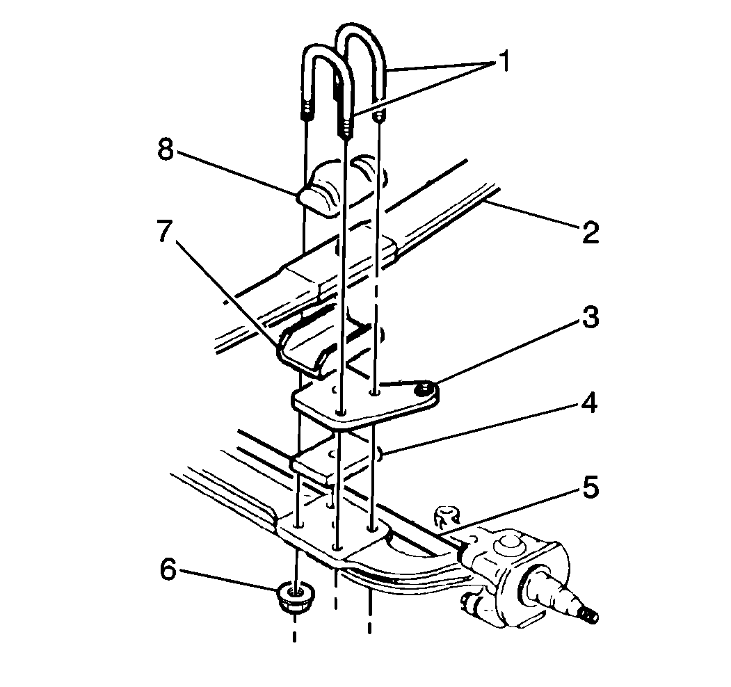
- Remove the nuts (6) and
the U-bolts (1).
- Lower the axle partially, and remove the U-bolt spacer (8).
- Remove the following components:
| • | The shock absorber brackets (3) |
- Remove the tie rods. Refer to
Tie Rod Arm Replacement
in Steering Linkage.
- Remove the relay rod. Refer to
Relay Rod Replacement
in Steering Linkage.
- Remove the axle from under the vehicle.
- Remove the kingpins and knuckles. Refer to
Steering Knuckle and King Pin Replacement
.
Inspection Procedure

- Clean the axle components
using a cleaning solvent.
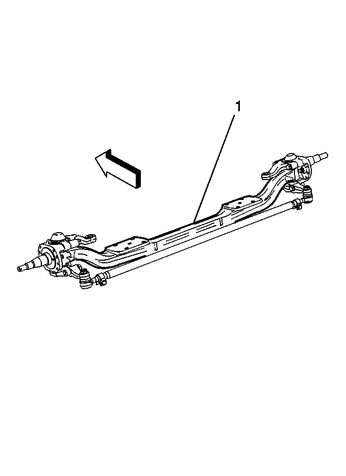
- Inspect the axle (1) for wear and damage. Use Magna-Flux™
inspection equipment if available. Inspect the axle for the following:
- Using alignment instruments, inspect the axle center for twist.
If the axle center has been twisted or bent more than 5 degrees (13 mm
or ½ in) from the original shape, replace the axle.
- Inspect the axle king pin bore for the following:
- Smooth the bore using a crocus cloth or fine grit sandpaper if
needed. Clean the bore.
Installation Procedure

- Install the steering knuckles
and king pins. Refer to
Steering Knuckle and King Pin Replacement
.
- Install the axle under the vehicle using a floor jack.
- Raise the axle and align the spring center bolt to the axle. Install
the following components:
Notice: Use the correct fastener in the correct location. Replacement fasteners
must be the correct part number for that application. Fasteners requiring
replacement or fasteners requiring the use of thread locking compound or sealant
are identified in the service procedure. Do not use paints, lubricants, or
corrosion inhibitors on fasteners or fastener joint surfaces unless specified.
These coatings affect fastener torque and joint clamping force and may damage
the fastener. Use the correct tightening sequence and specifications when
installing fasteners in order to avoid damage to parts and systems.
- Install the following
components:
Tighten
| • | Tighten the U-bolt nut to 225 N·m (166 lb ft)
for 8,100-pound axles.
|
| • | Tighten the U-bolt nut to 425 N·m (314 lb ft)
for all axles except 8,100-pound axles.
|

- Install the flat washer
(6) and the insulator (13) onto the shock absorber lower stem (5).
- Install the shock absorber (5) into the lower bracket (7).
- Install the following components:
| • | The lower insulator (8) |
Tighten
Tighten the lower shock absorber nut (10) to 84 N·m (62 lb ft).
- Install the tie rod ends into the tie rod arms. Refer to
Tie Rod Arm Replacement
in Steering Linkage.
- Install the relay rod. Refer to
Relay Rod Replacement
.
- Install the wheels, the hubs, and the bearings. Refer to
Front Wheel Hub, Bearing, and Seal Replacement
.
- Remove the safety stands and lower the vehicle.
- Install the stabilizer bar to the axle. Refer to
Stabilizer Shaft Replacement
.


