Removal Procedure
Caution: Unless directed otherwise, the ignition and start switch must be in the OFF or LOCK position, and all electrical loads must be OFF before servicing
any electrical component. Disconnect the negative battery cable to prevent an electrical spark should a tool or equipment come in contact with an exposed electrical terminal. Failure to follow these precautions may result in personal injury and/or damage to
the vehicle or its components.
- Disconnect
the battery negative cable.
- Drain the engine coolant. Refer to
Cooling System Draining and Filling
in Engine Cooling.
- Evacuate and recover theair conditioning (A/C) refrigerant, if
equipped. Refer to Refrigerant Recovery and Recharging
in HVAC Systems with A/C -- Manual.
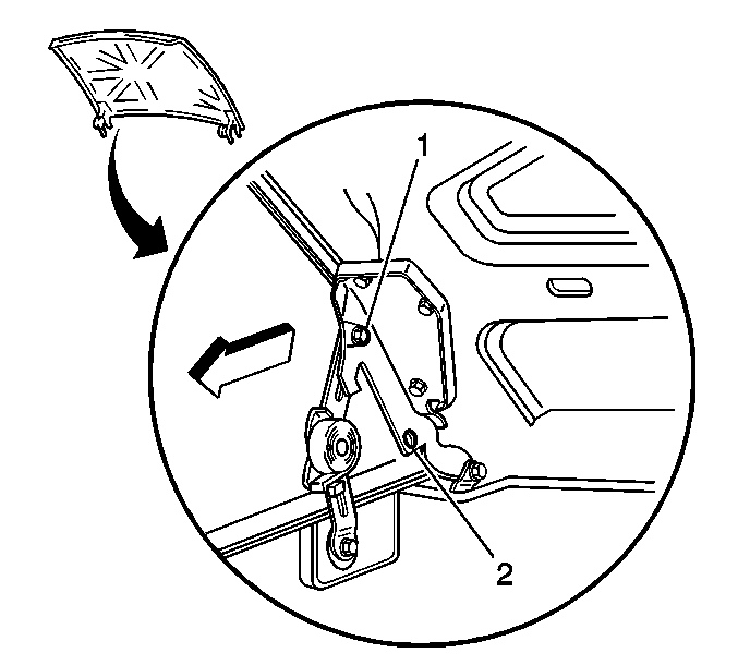
- Raise the hood to the
servicing position. Refer to
Hood Replacement
in Body Front End.
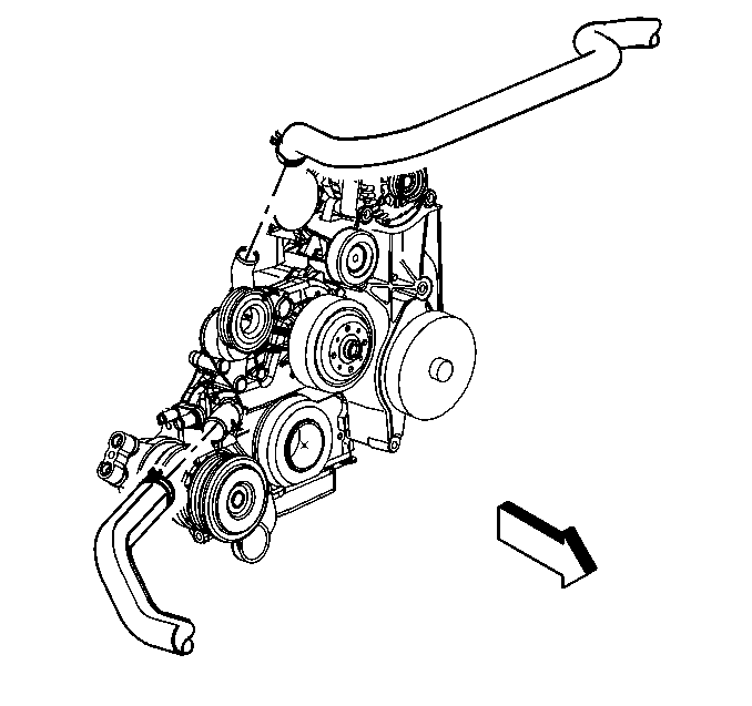
- Remove the upper and the
lower radiator hoses from the engine. Refer to
Radiator Outlet Hose Replacement
in Engine Cooling.
- Remove the air cleaner duct from the engine. Refer to
Air Cleaner Assembly Replacement
in Engine Controls
-- 4.8L, 5.3L, 6.0L.
- Remove the A/C condenser mounting bolts, if equipped. Refer to
Condenser Replacement
in HVAC Systems with A/C
-- Manual.
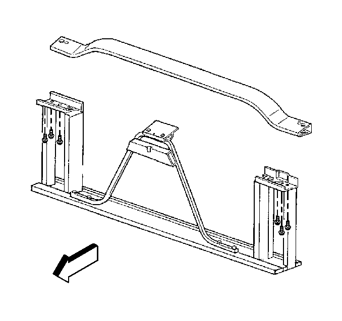
- Remove the upper radiator
support and the radiator from the vehicle.
Remove the following from body front end.
| • | Remove front bumper bolts and bumper |
| • | Remove hood latch cable from hood latch assembly |
| • | Disconnect engine vent hose from radiator |
| • | Disconnect engine surge tank hose from radiator |
| • | Remove engine oil cooler lines from radiator |
| • | Remove transmission oil cooler lines from radiator |
| • | Remove radiator mounting bolts and radiator |
| • | Remove lines from auxiliary transmission cooler |
| • | Remove power steering cooler retaining bolts |
| • | Remove hood latch assembly bolts and bracket assembly |
| • | Remove left front fender diagonal brace from upper radiator support |
| • | Remove upper radiator support bolts and support |
| • | Disconnect A/C lines from condenser |
| • | Remove A/C lines from compressor and position aside |
- Remove the A/C pressure hose from the A/C compressor, if equipped.
Set the A/C pressure hose aside. Refer to
Compressor Hose Assembly Replacement
in HVAC Systems with A/C --
Manual.
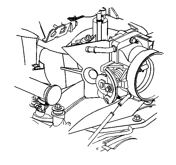
- Remove the coolant hose
from the throttle body.
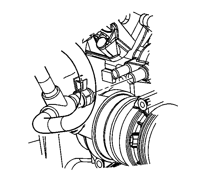
- Remove bothof the heater
hoses from the engine and the cowl. Refer to
Heater Hoses Replacement
in HVAC Systems with A/C -- Manual.
- Remove the engine sight shield from the intake manifold. Refer
to
Upper Intake Manifold Sight Shield Replacement
.
- Remove the accelerator control cable mounting bracket from the
intake manifold.
Caution: In order to avoid possible injury or vehicle damage, always replace
the accelerator control cable with a NEW cable whenever you remove the engine
from the vehicle.
In order to avoid cruise control cable damage, position the cable out
of the way while you remove or install the engine. Do not pry
or lean against the cruise control cable and do not kink the cable. You must
replace a damaged cable.
- Remove the accelerator control cable and the cruise control cable, if
equipped, from the throttle shaft. Refer to
Accelerator Control Cable Replacement
in Engine Controls --
4.8L, 5.3L, 6.0L.
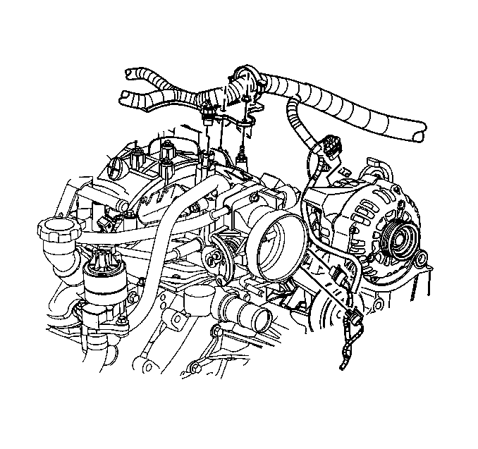
- Open the large electrical
harness retainer. Remove one 10 mm nut in order to release the engine
harness from the intake manifold.
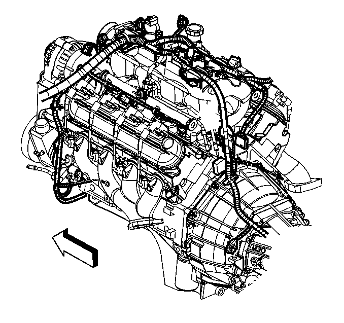
- Disconnect the following
electrical connectors:
| • | The eight injector connectors |
| • | The idle air control (IAC) motor |
| • | The throttle position (TP) sensor |
| • | The evaporative emissions (EVAP) canister purge solenoid |
| • | The manifold absolute pressure (MAP) sensor |
| • | The camshaft position (CMP) sensor |
| • | The ground splice at the rear of the right side of the block |
| • | The ground splice and the ground strap at the rear of the left
side of the block |
| • | The coolant temperature (CTS) sensor |
| • | The oil pressure sensor/switch |
| • | The A/C compressor clutch, if equipped |
| • | the electrical connector from intake and disconnect from harness |
| • | junction block bracket from genorator bracket |
- Set the electrical harness aside.
- Disconnect the EVAP canister purge solenoid vent tube from the
solenoid by squeezing the retainer, then release the tube from
the solenoid. Refer to
Evaporative Emission Canister Purge Solenoid Valve Replacement
in Engine
Controls -- 4.8L, 5.3L, 6.0L.
- Remove the battery negative cable from the engine block.
- Remove the drive belt. Refer to
Drive Belt Replacement
.
-
Generator Replacement in
Engine Electrical.
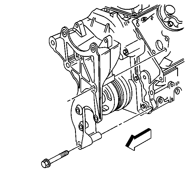
- Remove the generator mounting
bracket from the engine using the following steps:
| • | Remove the bolts holding the generator mounting bracket to the
cylinder head and block. |
| • | Remove the bolt behind the power steering pump to engine block. |
| • | Remove the generator mounting bracket. |
- Position the bracket aside.
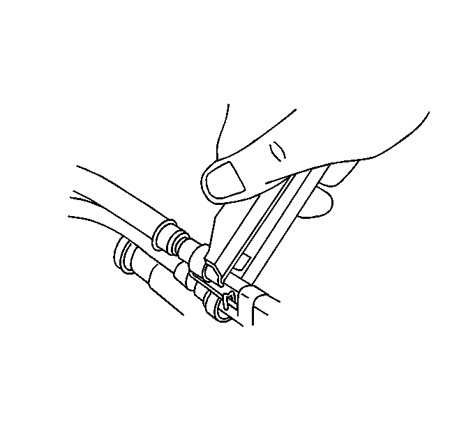
- Disconnect the fuel pipes
from the engine. Refer to Quick Connect Fitting(s) Service
(Metal Collar)
in Engine Controls -- 4.8L, 5.3L, 6.0L.
- Raise the vehicle. Refer to
Lifting and Jacking the Vehicle
in General Information.
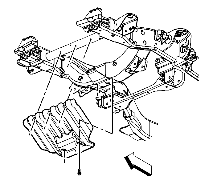
- Remove the steering linkage
under body shield, if equipped.
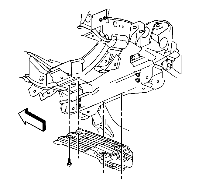
- Remove the engine oil
pan under body shield, if equipped.
- Drain the engine oil. Refer to
Engine Oil and Oil Filter Change
.
- Remove the starter motor. Refer to
Starter Motor Replacement
in Engine Electrical.
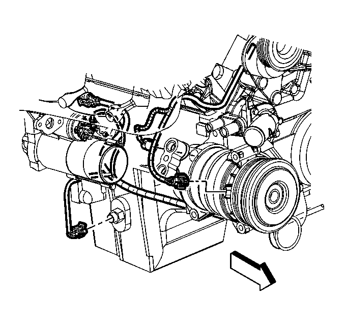
- Disconnect the engine
wiring harness from the following components:
| • | The crankshaft position (CKP) sensor |
| • | The engine oil level sensor |
| • | The A/C pressure switch, if equipped |
| • | The block heater, if equipped |
| • | The wiring harness to oil pan |
| • | Unrout wiring from lower engine area |
- Remove the exhaust pipes from the exhaust manifolds. Refer to
the appropriate procedure in Engine Exhaust from the following list:
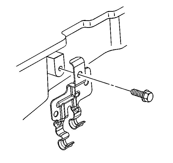
- Remove the transmission
cooler pipe retainer from the right side of the engine block, if equipped.
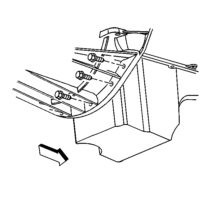
- Remove the torque converter
shield from the engine.
- Remove the torque converter bolts.
- Remove the nut and the transmission oil level indicator tube from
the bellhousing stud.
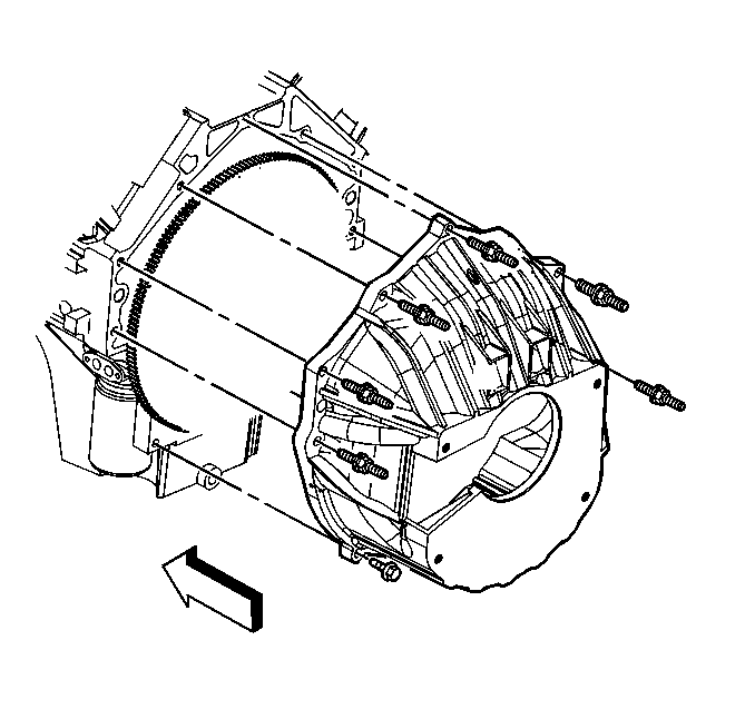
- Remove the lower bellhousing
studs from the engine. Refer to the appropriate procedure from the following
list:
- Lower the vehicle.
- Remove remaining bellhousing bolts.

- Position the engine electrical
harness aside.
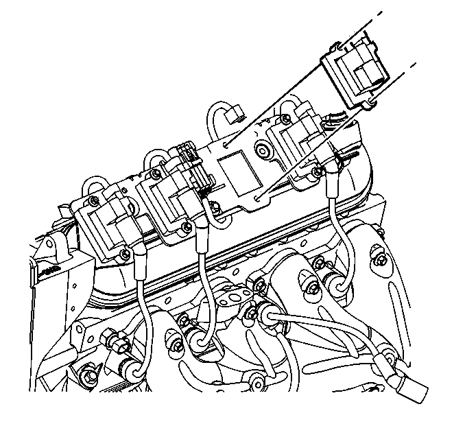
- Remove ignition coil(s)
(as required) for the proper fit of the J 41798
before lifting the engine. Refer to
Ignition Coil Replacement
in Engine Electrical.
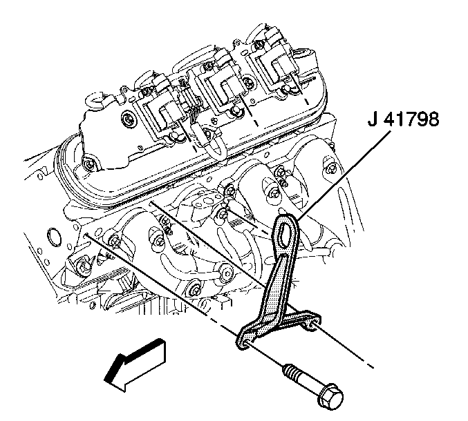
- Install the J 41798
engine lift brackets to the cylinder
heads.
Notice: Use the correct fastener in the correct location. Replacement fasteners
must be the correct part number for that application. Fasteners requiring
replacement or fasteners requiring the use of thread locking compound or sealant
are identified in the service procedure. Do not use paints, lubricants, or
corrosion inhibitors on fasteners or fastener joint surfaces unless specified.
These coatings affect fastener torque and joint clamping force and may damage
the fastener. Use the correct tightening sequence and specifications when
installing fasteners in order to avoid damage to parts and systems.
- Tighten the engine
lift bracket bolts to 55 N·m (41 lb ft).
- Install a lifting device onto the J 41798
engine lift brackets.
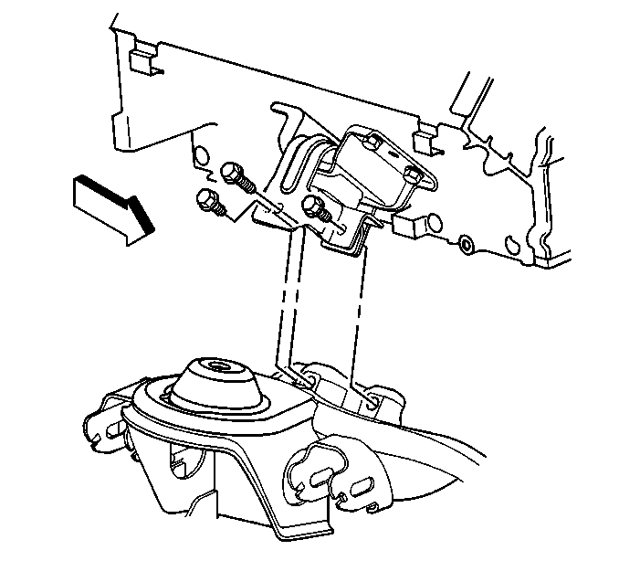
- Install floor jack or
stands to transmission for support.
- Remove the engine mount bolts. Refer to
Engine Mount Replacement
.
Notice: Use care while moving the engine assembly in order to avoid
breaking the MAP sensor locating tabs. Broken MAP sensor tabs may result in
decreased engine performance.
- Remove the engine from the vehicle.
Installation Procedure
Notice: Use care while moving the engine assembly in order to avoid
breaking the MAP sensor locating tabs. Broken MAP sensor tabs may result in
decreased engine performance.
- Install the engine to the vehicle.

- Install the engine mount
bolts. Refer to
Engine Mount Replacement
- Install upper bellhousing bolts.
- Remove transmission support apparatus
- Remove the lifting device from the J 41798
lift brackets.

- Remove the J 41798
lift brackets from both cylinder heads.

- Install the ignition coil(s)
and the spark plug wire(s) after removing the J 41798
. Refer to
Ignition Coil Replacement
in Engine Electrical.

- Route the engine wiring
harness to the lower right hand side of the engine.
- Raise the vehicle. Refer to
Lifting and Jacking the Vehicle
in General Information.
- Install remaining bellhousing bolts.
- Install torque converter bolts.
- Install torque converter shield
- Install transmission oil level indicator tube and nut to bellhousing
stud.
- Install transmission cooler pipe retainer to right side of engine
block.
Refer to the appropriate procedure from the following list:
- Install the engine exhaust pipes to the exhaust manifolds. Refer
to the appropriate procedure in Engine Exhaust from the following list:
- Reroute wiring to lower engine area and install bolt to oil pan.
- Connect electrical connectors to the crankshaft position (CKP)
sensor.
- The engine oil level sensor
- The A/C pressure switch, if equipped
- The block heater, if equipped
- Install the starter motor. Refer to
Starter Motor Replacement
in Engine Electrical.

- Install the engine oil
pan under body shield, if equipped.

- Install the steering linkage
under body shield.
- Lower the vehicle.
- Install the A/C compressor hose to the A/C compressor, if equipped.
Refer to
Compressor Hose Assembly Replacement
in HVAC Systems with A/C -- Manual.
- Connect the fuel pipes to the engine. Refer to Quick Connect Fitting(s) Service (Metal Collar)
in Engine Controls
-- 4.8L, 5.3L, 6.0L.

Notice: Use the correct fastener in the correct location. Replacement fasteners
must be the correct part number for that application. Fasteners requiring
replacement or fasteners requiring the use of thread locking compound or sealant
are identified in the service procedure. Do not use paints, lubricants, or
corrosion inhibitors on fasteners or fastener joint surfaces unless specified.
These coatings affect fastener torque and joint clamping force and may damage
the fastener. Use the correct tightening sequence and specifications when
installing fasteners in order to avoid damage to parts and systems.
- Install the generator
mounting bracket to the cylinder head using the nuts and the bolts.
Tighten
Tighten the bolts to 50 N·m (37 lb ft).
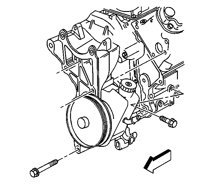
- Install the bolt at the
rear of the power steering pump to engine block.
Tighten
Tighten the bolt to 50 N·m (37 lb ft).
- Install the generator to the engine. Refer to
Generator Replacement
in Engine Electrical.
- Install the drive belt. Refer to
Drive Belt Replacement
- Install the battery negative cable to the engine block. Refer
to
Fastener Tightening Specifications
.
- Install the EVAP canister purge solenoid to the intake manifold.
Refer to
Evaporative Emission Canister Purge Solenoid Valve Replacement
in Engine Controls -- 4.8L,
5.3L, 6.0L.

- Route the engine harness
over the top of the engine. Connect the following components:
| • | The eight injector connectors |
| • | The idle air control (IAC) motor |
| • | The throttle position (TP) sensor |
| • | The EVAP canister purge solenoid. |
| • | The manifold absolute pressure (MAP) sensor |
| • | The camshaft position (CMP) sensor |
| • | The ground splice at the rear of the right side of engine block |
| • | The ground splice and the ground strap at the rear of the left
side of engine block |
| • | The coolant temperature (CTS) sensor |
| • | The oil pressure sensor/switch |
| • | A/C compressor clutch electrical connector to harness and reclip
to intake manifold |

- Install the nut to the
engine wiring harness bracket.
Tighten
Tighten the nut to 10 N·m (89 lb in).
Caution: In order to avoid possible injury or vehicle damage, always replace
the accelerator control cable with a NEW cable whenever you remove the engine
from the vehicle.
In order to avoid cruise control cable damage, position the cable out
of the way while you remove or install the engine. Do not pry
or lean against the cruise control cable and do not kink the cable. You must
replace a damaged cable.
- Install a NEW accelerator control cable. Refer to
Accelerator Control Cable Replacement
in Engine
Controls -- 4.8L, 5.3L, 6.0L.
Install cruise control cable, if equipped, to the throttle shaft. Refer
to
Accelerator Control Cable Replacement
. in Engine Controls -- 4.8L, 5.3L, 6.0L.
- Install the bolts for the accelerator control cable mounting bracket.
Tighten
Tighten the bolts to 10 N·m (89 lb in).
- Install the engine sight shield to the intake manifold. Refer
to
Upper Intake Manifold Sight Shield Replacement
.

- Install both heater hoses
to the cowl and the engine. Refer to
Heater Hoses Replacement
in HVAC Systems with A/C --
Manual.

- Install the coolant hose
to the throttle body.

- Install the upper radiator
support and the radiator. Refer to
Radiator Support Replacement
in Body Front End.
- Install the A/C condenser mounting bolts, if equipped. Refer to
Condenser Replacement
in HVAC Systems with A/C
-- Manual.
- Install the air cleaner duct. Refer to
Air Cleaner Assembly Replacement
in Engine Controls -- 4.8L,
5.3L, 6.0L.
- Install the upper and the lower radiator hoses to the engine.
Refer to
Radiator Outlet Hose Replacement
in Engine
Cooling.

- Lower the hood. Refer
to
Hood Replacement
in Body
Front End.
- Fill the engine with oil. Refer to
Engine Oil and Oil Filter Change
.
- Fill the engine with coolant. Refer to
Cooling System Draining and Filling
in Engine Cooling.
- Connect the negative battery cable.


