Special Tools
J 36857 Engine Lift Bracket
Removal Procedure
- Block the wheels.
- Remove the air cleaner. Refer to Air Cleaner Assembly Replacement.
- Remove the engine cover. Refer to Engine Cover Replacement.
- Disconnect the battery negative cables. Refer to Battery Negative Cable Disconnection and Connection.
- Remove the cooling layer. Refer to Cooling Layer Removal.
- Drain the engine coolant and the engine block. Refer to Cooling System Draining and Filling.
- Raise the vehicle. Refer to Lifting and Jacking the Vehicle. Support the vehicle so that the transmission jack will not contact the tie rod when removing the engine and transmission.
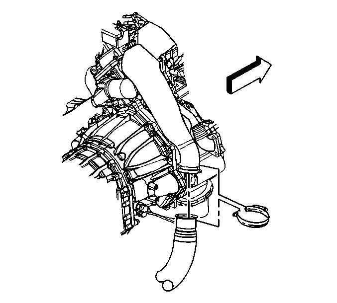
- Remove the charged air cooler pipes and hoses from the engine. Refer to Charged Air Cooler Hoses/Pipes Replacement.
- Remove the engine front crossmember. Refer to Engine Front Crossmember Replacement.
- Disconnect the outlet heater hose from the outlet radiator pipe at the engine.
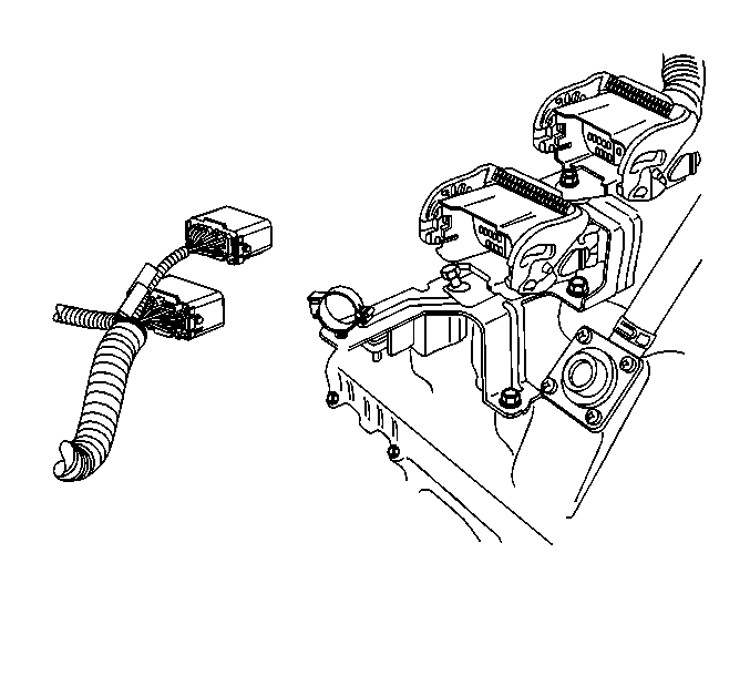
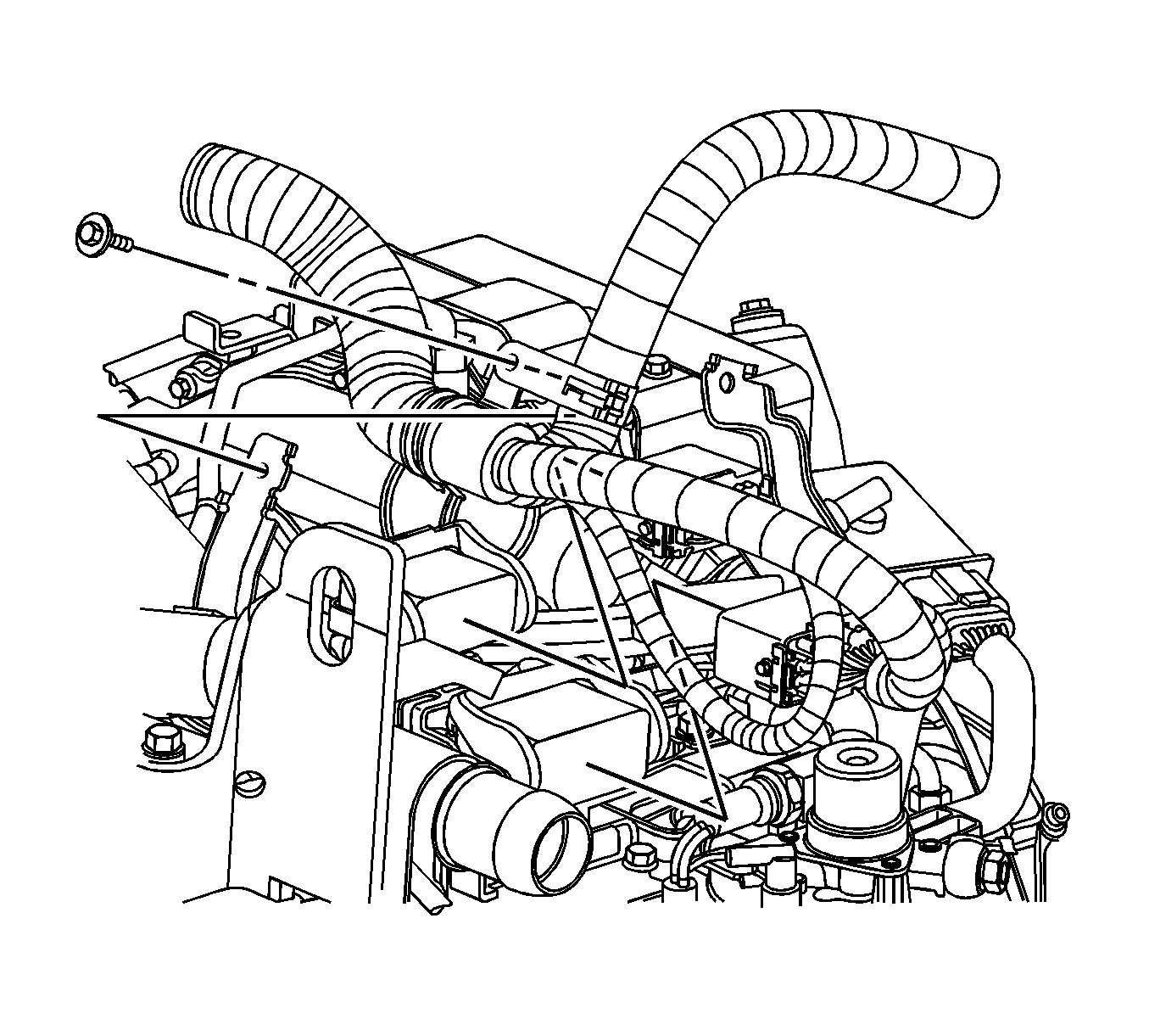
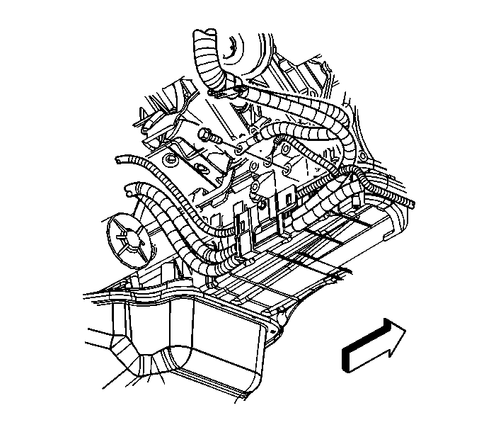
- Remove the engine wire harness from all connectors and retainers. Refer to Engine Wiring Harness Assembly Removal.
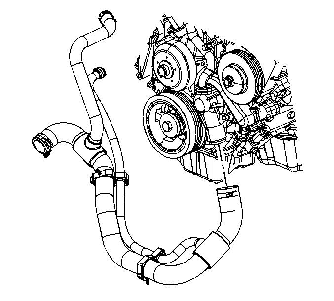
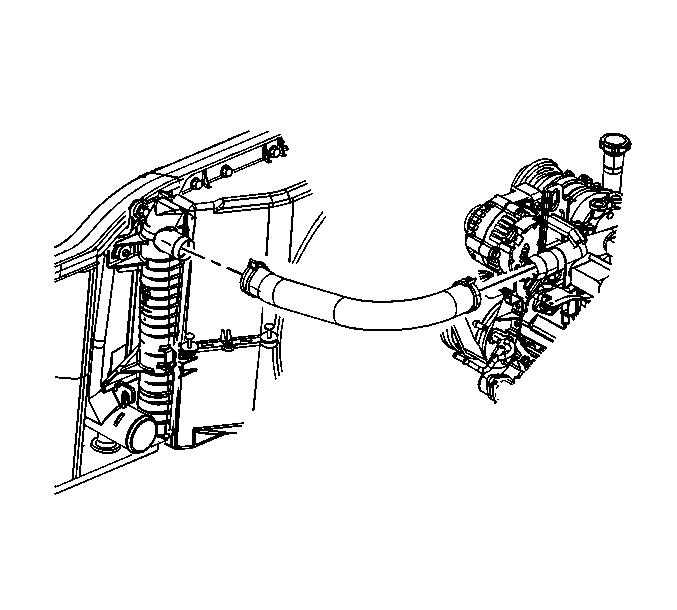
- Loosen the hose clamp and remove the radiator outlet hose from the engine.
- Loosen the hose clamp and remove the radiator inlet hose from the engine.
- Disconnect the fuel lines at the engine. Refer to Metal Collar Quick Connect Fitting Service.
- Secure the fuel lines out of the way.
- Remove the bolts retaining the power steering pump front bracket to the power steering pump and the air conditioner compressor mounting bracket. Refer to Air Conditioning (A/C) Compressor and Power Steering Pump Bracket Replacement. Secure the pump out of the way.
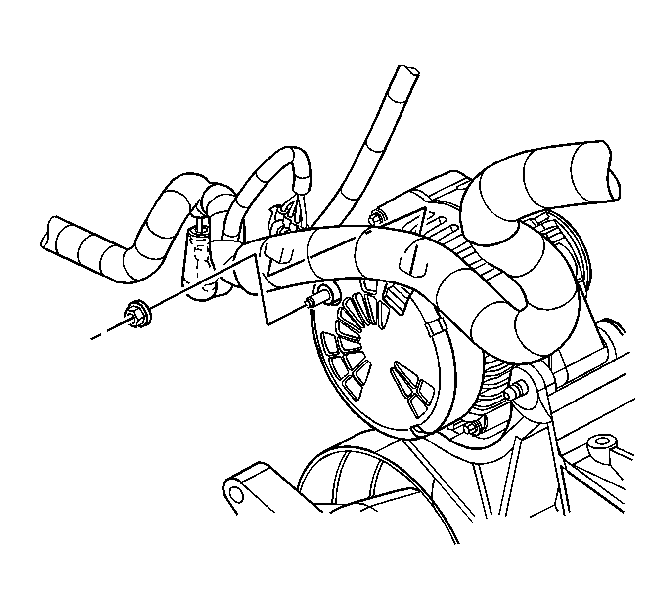
- Disconnect the battery cable to the generator.
- If equipped with an auxiliary generator, disconnect the battery cable.
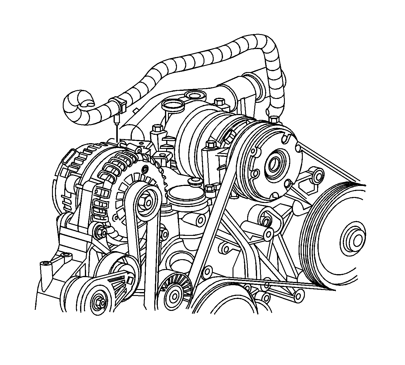
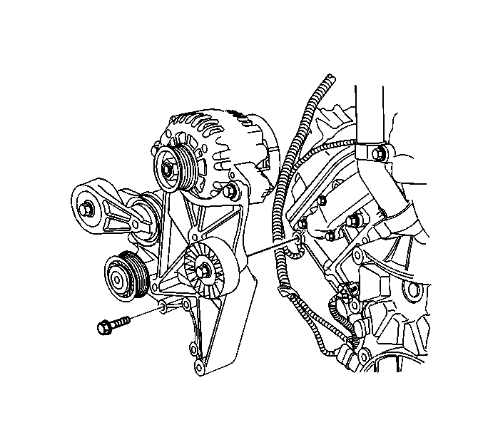
- Remove the generator mounting bracket and secure to the side. Refer to Generator Replacement.
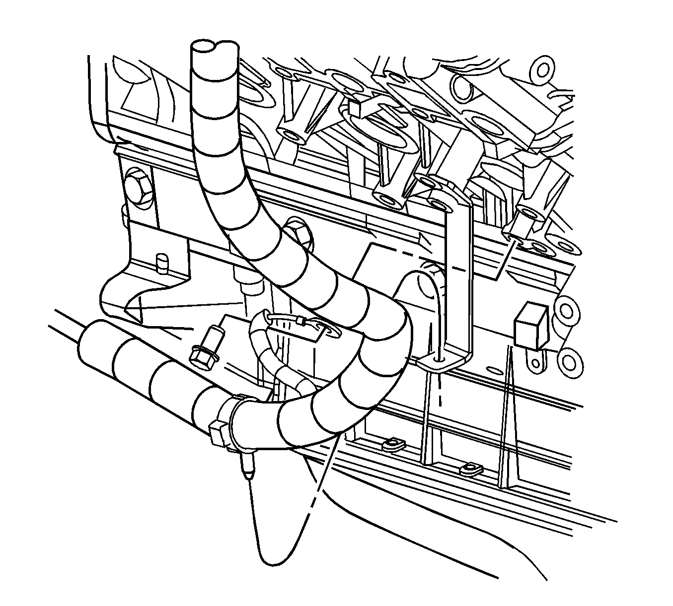
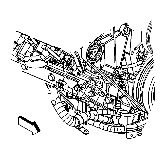
- Remove the bolt and the ground wires at the right side of the engine block.
- Remove the ground strap and harness from the right side of the engine.
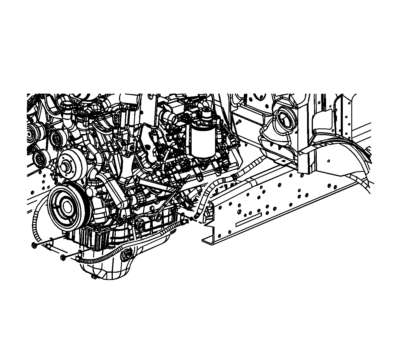
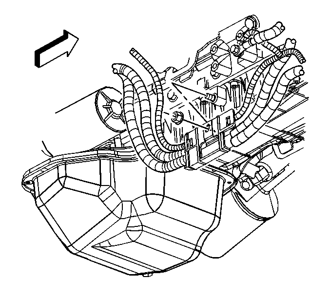
- If equipped, remove the bolts holding the harness cable retainers to the lower crankcase.
- If equipped, disconnect the cord from the engine coolant heater and position out of the way.
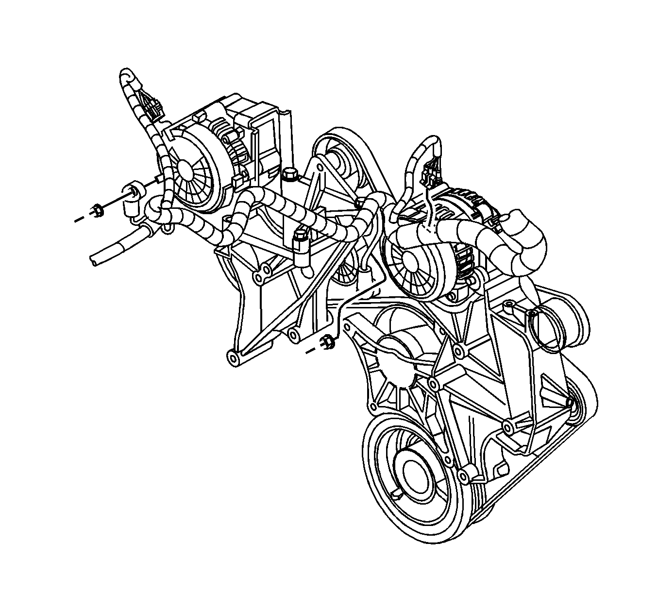
- If equipped, remove the nut holding the battery cable bracket to the right side of the lower crankcase.
- Remove the bolt holding the auxiliary battery negative cable and the engine wiring harness ground wires to the right side of the engine.
- Move and secure the battery cables out of the way.
- Drain the engine oil.
- Remove the propeller shaft. Refer to One-Piece Rear Propeller Shaft Replacement or to Two-Piece Rear Propeller Shaft Replacement or to Three-Piece Rear Propeller Shaft Replacement.
- Remove the park brake cable. Refer to Parking Brake Cable Replacement.
- Remove the exhaust pipe outlet clamp. Move the clamp onto the exhaust pipe.
- Install a J 36857 to both rear cylinder heads.
- Install a J 36857 (1) to both front cylinder heads.
- Connect the 2 rear lift points with a small chain.
- Connect the 2 front lift points with a small chain.
- Install a suitable lifting device to the front chain. The engine will have to be angled in order to remove. Use a load positioning sling to assist in angling the engine.
- If equipped with an automatic transmission, perform steps 38-50.
- Drain the transmission oil. Refer to Automatic Transmission Fluid and Filter Replacement.
- Remove the transmission oil level indicator and the oil level indicator tube. Refer to Transmission Fluid Filler Tube and Seal Replacement.
- If equipped, remove the transmission heat shield fasteners and the heat shield from the transmission.
- Remove the starter. Refer to Starter Motor Replacement.
- If equipped, remove the oil cooler lines from the transmission. Refer to Transmission Fluid Auxiliary Cooler Inlet and Outlet Hose Replacement.
- If equipped, remove the shift cable from the transmission.
- Remove the wiring harness and disconnect the transmission electrical connectors.
- If equipped, remove the flywheel housing access cover.
- Mark the flywheel and torque converter or the flex plate relationship for reassembly purposes.
- Turn the flex plate using a pry bar or the engine harmonic balancer, in order to align the torque converter or flex plate bolts with the access hole or starter hole.
- Remove the torque converter bolts through the starter opening.
- If equipped, remove the fuel line from the fuel line bracket.
- If equipped, remove the fuel line retainer bracket from the transmission.
- If equipped with a manual transmission, perform the following:
- Using a transmission jack, support the rear of the transmission.
- Install a safety chain to secure the transmission to the transmission jack.
- Remove the transmission mount mounting bolts from the transmission. Refer to Transmission Mount Replacement.
- Remove the left and right front engine mounting bolts. Refer to Engine Mount Bracket Replacement - Left Side and to Engine Mount Bracket Replacement - Right Side.
- Ensure the wiring harness does not become hung up on the engine.
- Pull the engine forward far enough to connect to the rear engine lift eye.
- Attach the load leveling device to the rear engine lift eye.
- Remove the transmission jack.
- Remove the engine and transmission from the vehicle.
- If equipped with an automatic transmission, perform the following:
- If equipped with a manual transmission perform the following:
- In order to secure the engine to an engine stand, refer to Engine Mounting to Stand and remove the following:
| • | The generator does not require removal. |
| • | The drive belt tensioner does not require removal. |

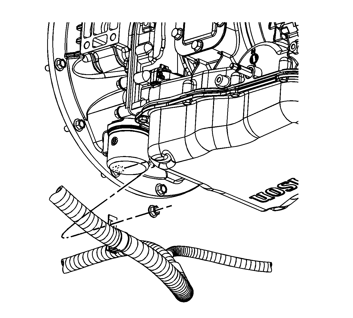
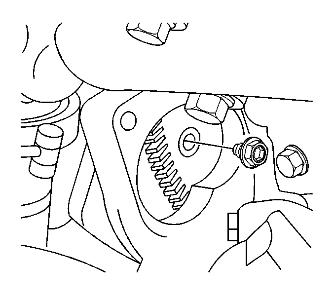
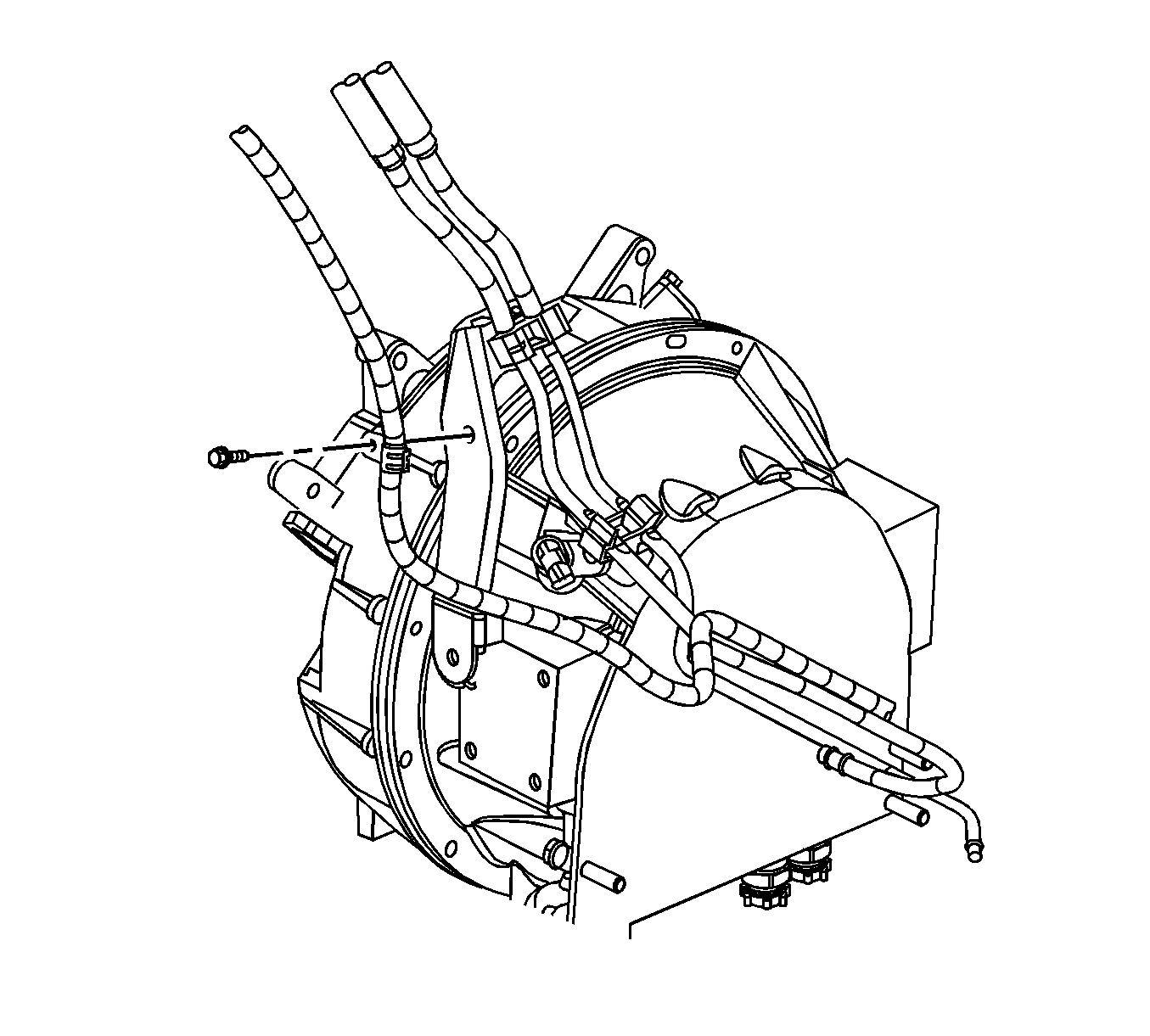
| 50.1. | Remove all electrical connectors from the transmission. |
| 50.2. | Remove all electrical harness retainers from the transmission. |
| 50.3. | If required, raise the vehicle. Refer to Lifting and Jacking the Vehicle. |
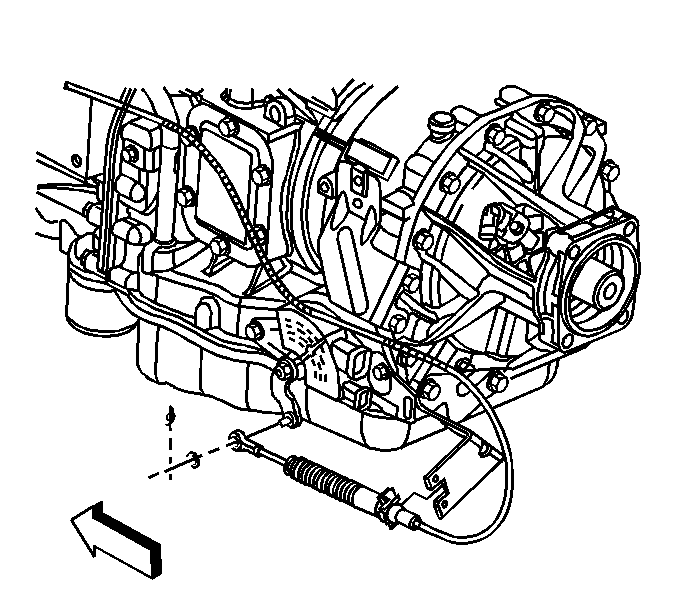
| 50.4. | Remove the clutch cable and bracket from the transmission. Refer to Clutch Cable Return Spring and/or Bracket Replacement. |
| 50.5. | Remove the control lever and boot. Refer to Control Lever and/or Boot Replacement. |
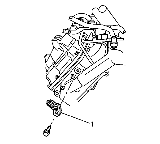
| 50.6. | If equipped, remove the fuel line retainers from the transmission. |
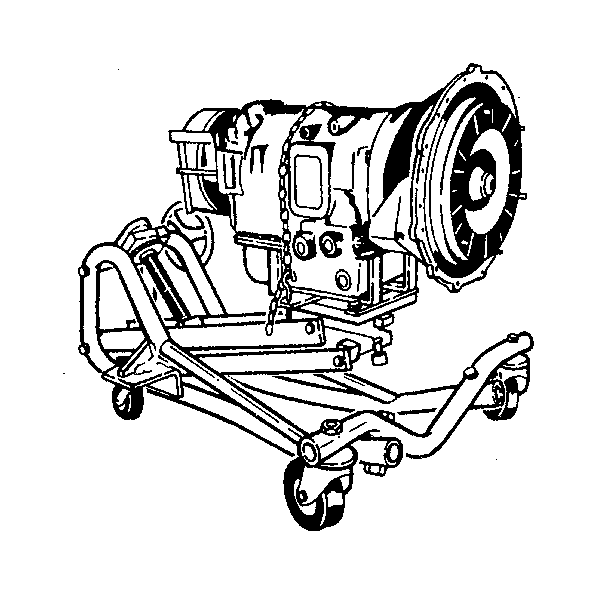
Note: Support the transmission with a transmission jack that can support a load of at least 349 kg (750 lb).
| 60.1. | Attach the transmission jack. |
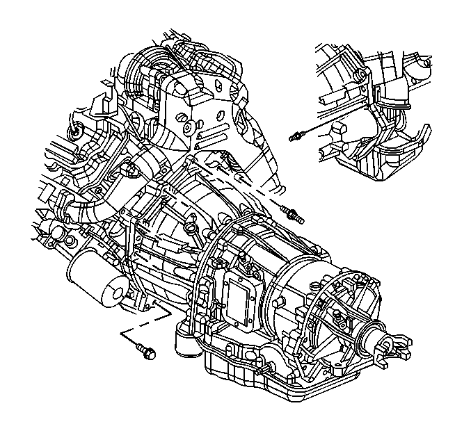
| 60.2. | Remove the bolts securing the transmission to the engine. |
| 60.3. | Remove the transmission from the engine by sliding the transmission rearward. |
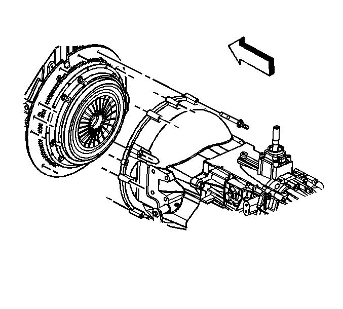
| 61.1. | Attach the transmission jack. |
| 61.2. | Remove the transmission apron housing bolts. |
| Caution: When removing the transmission, do not allow the weight of the transmission to hang on the clutch disc hub. The clutch disc will become distorted and seriously affect the operation of the clutch. |
| 61.3. | Move the transmission straight back from the engine, keeping the mainshaft in alignment with the clutch disc hub. |
| 61.4. | When the transmission is free from the engine, lower and remove the transmission. |
| • | The engine flywheel--Refer to Engine Flywheel Replacement. |
| • | The exhaust outlet--Refer to Exhaust Outlet Removal. |
| • | The lower oil pan--Refer to Lower Oil Pan Removal. |
| • | The upper oil pan--Refer to Upper Oil Pan Removal. |
| • | The engine flywheel housing--Refer to Engine Flywheel Housing Removal. |
Installation Procedure
- Install a J 36857 (1) to both front cylinder heads.
- Install a J 36857 to both rear cylinder heads.
- Connect a short chain to the 2 front J 36857 (1).
- Connect a short chain to the 2 rear J 36857 .
- Install a suitable lifting device. The engine will have to be angled in order to install. Use a load positioning sling to assist in angling the engine.
- Remove the engine from the stand. Refer to Engine Removal from Stand.
- Install the following:
- If equipped with a manual transmission, perform steps 9-15.
- Shift the transmission into high gear.
- With the transmission mounted to suitable dolly, move the transmission into position under the vehicle.
- Rotate the output shaft to align the main drive gear shaft with the clutch disc hub.
- Move the transmission forward, guiding the main drive gear shaft into the clutch disc hub.
- Install the transmission.
- Install the transmission apron housing bolts.
- Remove the transmission jack.
- If equipped with an automatic transmission, perform the following:
- Position the engine and transmission into the vehicle as far as possible.
- Install the transmission jack.
- Install a safety chain to secure the transmission to the transmission jack.
- Remove the leveling device from the rear engine lift chain eye only.
- Install the engine and transmission to the engine mounts.
- Install the left and right front engine mount bolts. Refer to Engine Mount Bracket Replacement - Left Side and to Engine Mount Bracket Replacement - Right Side.
- Install the transmission mount to the transmission. Refer to Transmission Mount Replacement.
- If equipped with an automatic transmission, perform the following:
- Remove the overhead hoist.
- Remove the transmission jack.
- Install the starter assembly. Refer to Starter Motor Replacement.
- Install the parking brake cable to the park brake linkage.
- If equipped with a manual transmission, perform the following:
- If equipped with an automatic transmission perform the following:
- If equipped, install the fuel line brackets.
- If equipped, install the fuel lines to the fuel line brackets.
- Install the propeller shaft to the transmission. Refer to One-Piece Rear Propeller Shaft Replacement or to Two-Piece Rear Propeller Shaft Replacement or to Three-Piece Rear Propeller Shaft Replacement.
- If equipped with an automatic transmission, install the transmission oil cooler lines.
- Lower the vehicle, if required.
- Install the exhaust pipe to the exhaust outlet.
- Install the exhaust manifold pipe to the exhaust outlet clamp.
- Install the harness cable to the lower crankcase with 2 bolts.
- Install the bolts holding the auxiliary battery negative cable and the engine wiring harness ground wires to the right side of the engine.
- Install the engine harness to retainer and ground lead to engine block.
- If equipped, install the nut holding the battery cable bracket to the right side of the lower crankcase.
- Install the starter. Refer to Starter Motor Replacement.
- If equipped, connect the cord for the engine coolant heater.
- Install the generator mounting bracket and bolts.
- If equipped, install the battery cable to the auxiliary generator.
- Install the battery cable to the generator.
- Connect the engine wiring harness to all connectors on the engine.
- Connect the fuel hoses at the engine.
- Connect both fuel injection control module harness connectors.
- Install the engine wire harness in the retainer.
- Connect all engine wiring to all connectors. Refer to Engine Wiring Harness Assembly Installation.
- Install the outlet radiator hose to the engine and tighten the hose clamp.
- Install the inlet radiator hose to the engine and tighten the hose clamp.
- Install the cooling layer. Refer to Cooling Layer Installation.
- Connect the inlet heater hose to the heater pipe inlet.
- Install the engine wire harness clip to the engine bracket.
- Install the charged air cooler pipes and hoses to the turbocharger and the charged air cooler. Refer to Charged Air Cooler Hoses/Pipes Replacement.
- Fill the engine with the proper capacity and quality of engine oil. Refer to Fluid and Lubricant Recommendations and to Engine Mechanical Specifications.
- Install the air cleaner. Refer to Air Cleaner Assembly Replacement.
- Connect the battery negative cables. Refer to Battery Negative Cable Disconnection and Connection.
- Install the engine cover. Refer to Engine Cover Replacement.
- If equipped with a manual transmission, install the control lever and boot. Refer to Control Lever and/or Boot Replacement.
- Operate the engine, inspect for coolant, oil, fuel, and exhaust leaks.
- Inspect for proper oil pressure.
- Inspect for proper engine operation.
- Road test the vehicle for normal operation.
- Inspect for coolant, oil, fuel and exhaust leaks.

| • | The engine flywheel housing--Refer to Engine Flywheel Housing Removal. |
| • | The engine flywheel--Refer to Engine Flywheel Replacement. |
| • | The exhaust outlet--Refer to Exhaust Outlet Removal. |
| • | The lower oil pan--Refer to Lower Oil Pan Removal. |
| • | The upper oil pan--Refer to Upper Oil Pan Removal. |
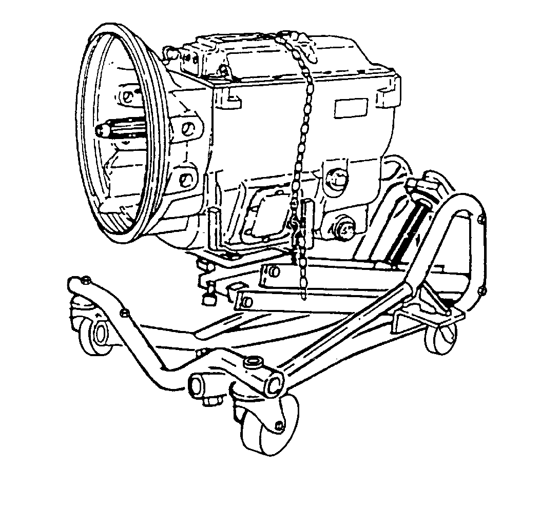

| • | Avoid springing the clutch when installing the transmission. |
| • | Do not allow the transmission to drop or hang unsupported in the splined hub of the clutch disc. |
Caution: Refer to Fastener Caution in the Preface section.
Tighten
Tighten the transmission apron housing bolts to 50 N·m (37 lb ft).
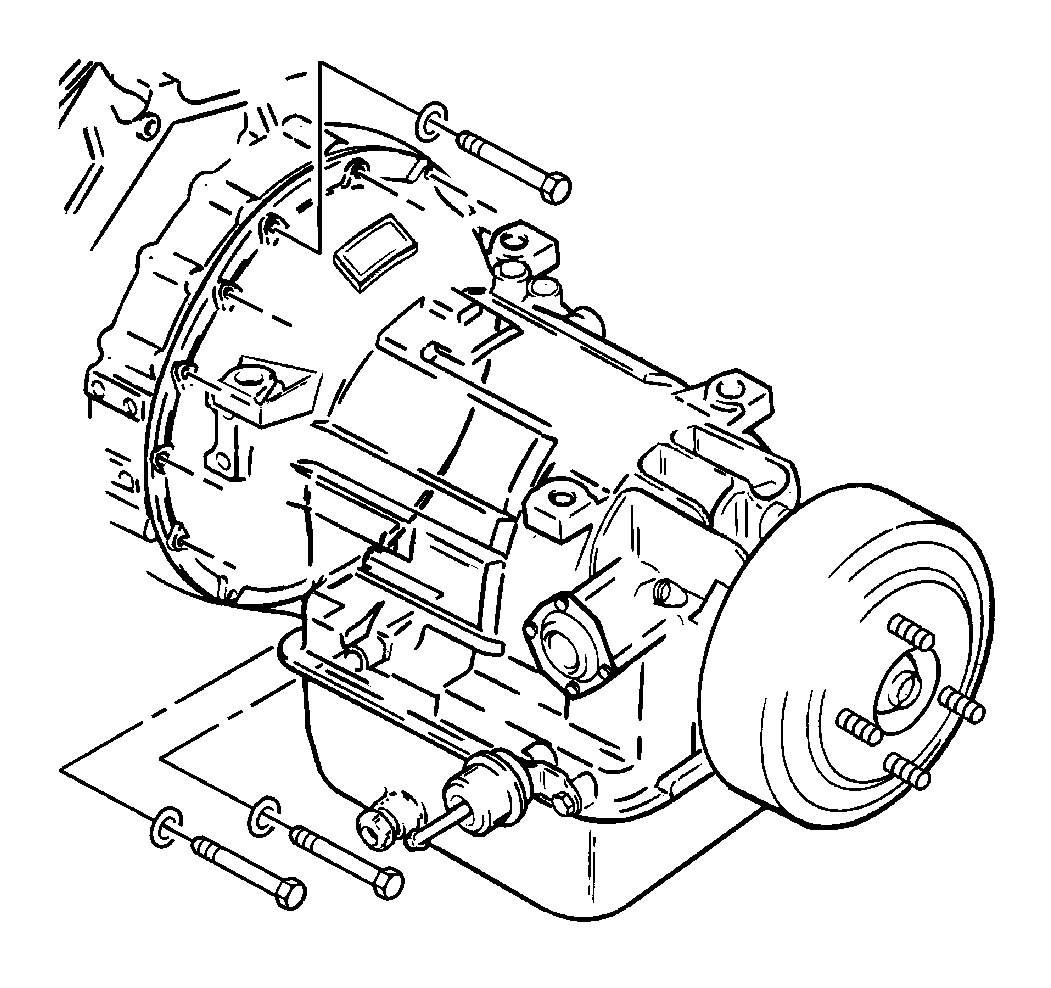
| 16.1. | Reattach the transmission jack. |
| 16.2. | Raise the transmission to the engine. |
| 16.3. | Install the transmission to the engine while aligning the torque converter with the engine flex plate. |
| 16.4. | Install the transmission to the engine bolts. |
Tighten
Tighten the transmission to engine bolts to 50 N·m (37 lb ft).
| 16.5. | Install the nuts retaining the transmission fluid fill tube bracket. |
Tighten
Tighten the transmission fluid fill tube bracket nuts to 18 N·m (13 lb ft).
| 16.6. | Install a long leveling devise to the 2 chains and support the engine and transmission. |
| 16.7. | Remove the transmission jack. |

Note: Support the transmission with a transmission jack that can support a load of at least 349 kg (750 lb).
| 24.1. | Turn the engine flex plate using a pry bar or engine at the harmonic balancer in order to install the torque converter to the flywheel bolts. |
| 24.2. | When reusing the torque converter bolts, clean the bolts and apply LOCTITE™. |
| 24.3. | Install the converter bolts. |
Tighten
Tighten the torque converter to flywheel bolts to 60 N·m (44 lb ft).
| 24.4. | If equipped, install the flywheel housing access cover. |

| 29.1. | Install all electrical connectors to the transmission. |
| 29.2. | Install all electrical harness retainers. |
| 29.3. | Install the clutch and bracket. Refer to Clutch Cable Return Spring and/or Bracket Replacement. |
| 30.1. | If equipped, install the oil cooler lines to the transmission. Refer to Transmission Fluid Auxiliary Cooler Inlet and Outlet Hose Replacement. |
| 30.2. | Install the oil level indicator tube. Refer to Transmission Fluid Filler Tube and Seal Replacement. |
| 30.3. | Connect the transmission electrical connectors and install the wiring harness to the transmission. |
| 30.4. | If equipped, install the transmission heat shield with 2 bolts. |
Tighten
Tighten the transmission heat shield bolts to 15 N·m (11 lb ft).

| 30.5. | If equipped, install the shift cable to the transmission. |
| 30.6. | If equipped, install the transmission heat shield with 2 bolts. |
Tighten
Tighten the transmission heat shield bolts to 15 N·m (11 lb ft).


Tighten
Tighten the exhaust pipe clamp to 40 N·m (30 lb ft).

Tighten
Tighten the cable bracket bolts to 12 N·m (106 lb in).

Tighten
Tighten the cable and ground wire bolts to 34 N·m (25 lb ft).


Tighten
Tighten the cable bracket nut to 8 N·m (71 lb in).


Tighten
Tighten the generator mounting bracket bolts to 50 N·m (37 lb ft).


Tighten
Tighten the generator battery cable nut to 9 N·m (80 lb in).
