Special Tools
J 36660-A
Torque Angle Meter
Removal Procedure
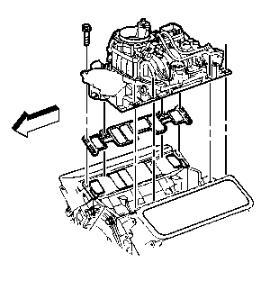
- Remove the intake manifold. Refer to
Intake Manifold Replacement
.
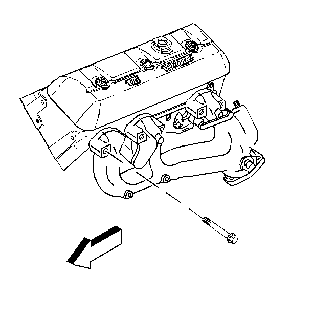
- Remove the exhaust manifold. Refer to
Exhaust Manifold Replacement
.
- Remove the following components from the left cylinder head.
| • | The electrical connector at the rear of the cylinder head for the coolant temperature sensor. |
| • | The air conditioning compressor and bracket. Refer to Heating, Ventilation and Air Conditioning. |
- Remove the generator and bracket from the right cylinder head. Refer to Engine Electrical.
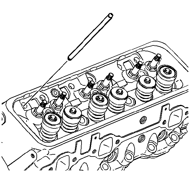
- Remove the pushrods. Refer to
Valve Rocker Arm and Push Rod Replacement
. If reusing the pushrods, install them in their original location.
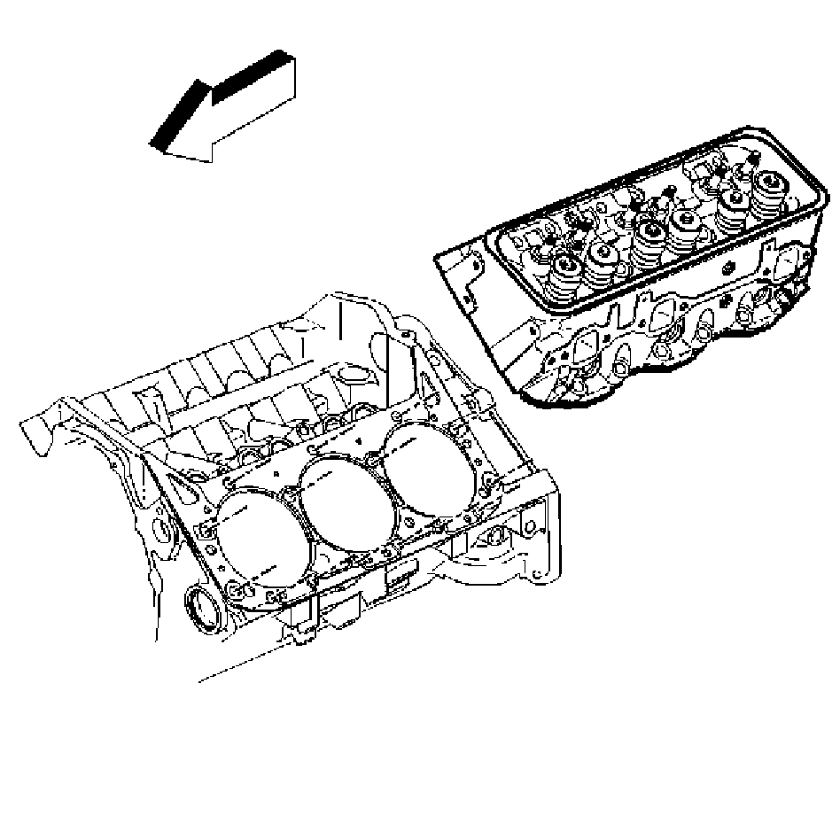
- Remove the cylinder head and discard the cylinder head bolts.
Installation Procedure
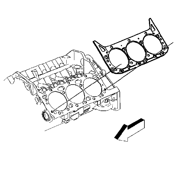
- Install the new cylinder head gasket.
- Install the gasket over the locating pins, with the yellow side of the tab on the outboard side facing up.
Important: Cylinder head gaskets do not require sealant.
- Install the cylinder head over the locating pins and the gasket.
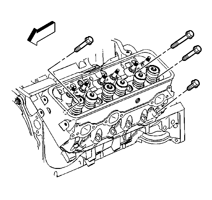
- Coat the threads of the
NEW
cylinder head bolts with sealing compound GM P/N 12346004, or equivalent.
- Install the cylinder head bolts finger tight.
Notice: Use the correct fastener in the correct location. Replacement fasteners
must be the correct part number for that application. Fasteners requiring
replacement or fasteners requiring the use of thread locking compound or sealant
are identified in the service procedure. Do not use paints, lubricants, or
corrosion inhibitors on fasteners or fastener joint surfaces unless specified.
These coatings affect fastener torque and joint clamping force and may damage
the fastener. Use the correct tightening sequence and specifications when
installing fasteners in order to avoid damage to parts and systems.
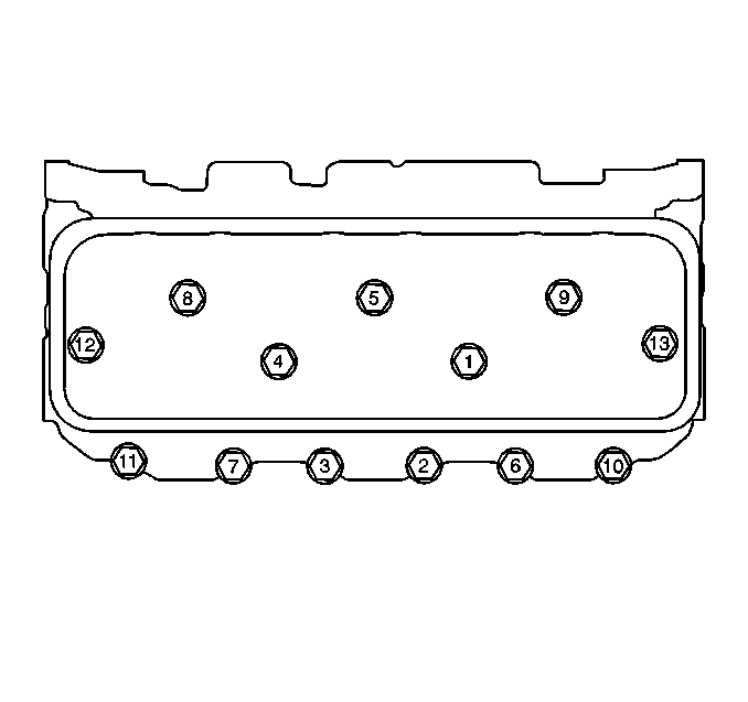
- Use a two-step tightening sequence as outlined below.
Tighten
Tighten the cylinder head bolts in sequence on the first pass to 30 N·m (22 lb ft).
- Use the
J 36660-A
Torque Angle Meter
Tighten
| • | Tighten the short bolts (11, 7, 3, 2, 6, 10) an additional 55 degrees. |
| • | Tighten the medium bolts (12, 13) an additional 65 degrees. |
| • | Tighten the long bolts (1, 4, 8, 5, 9) an additional 75 degrees. |

- Install the pushrods. Refer to
Valve Rocker Arm and Push Rod Replacement
.
- Install the following components to the left cylinder head:
| 9.1. | The electrical connector at the coolant temperature sensor |
| 9.2. | The air conditioning compressor and bracket. Refer to Heating, Ventilation and Air Conditioning. |
- Install the generator and bracket to the right cylinder head. Refer to Engine Electrical.
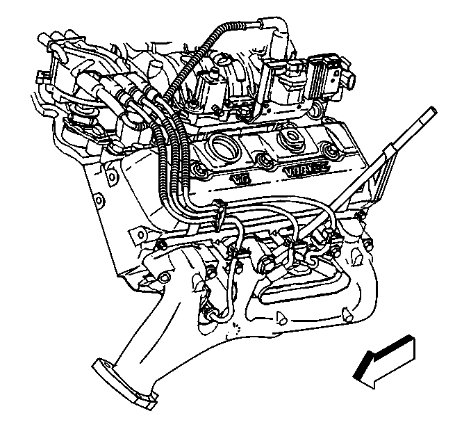
- Install the exhaust manifold. Refer to
Exhaust Manifold Replacement
.

- Install the intake manifold. Refer to
Intake Manifold Replacement
.


