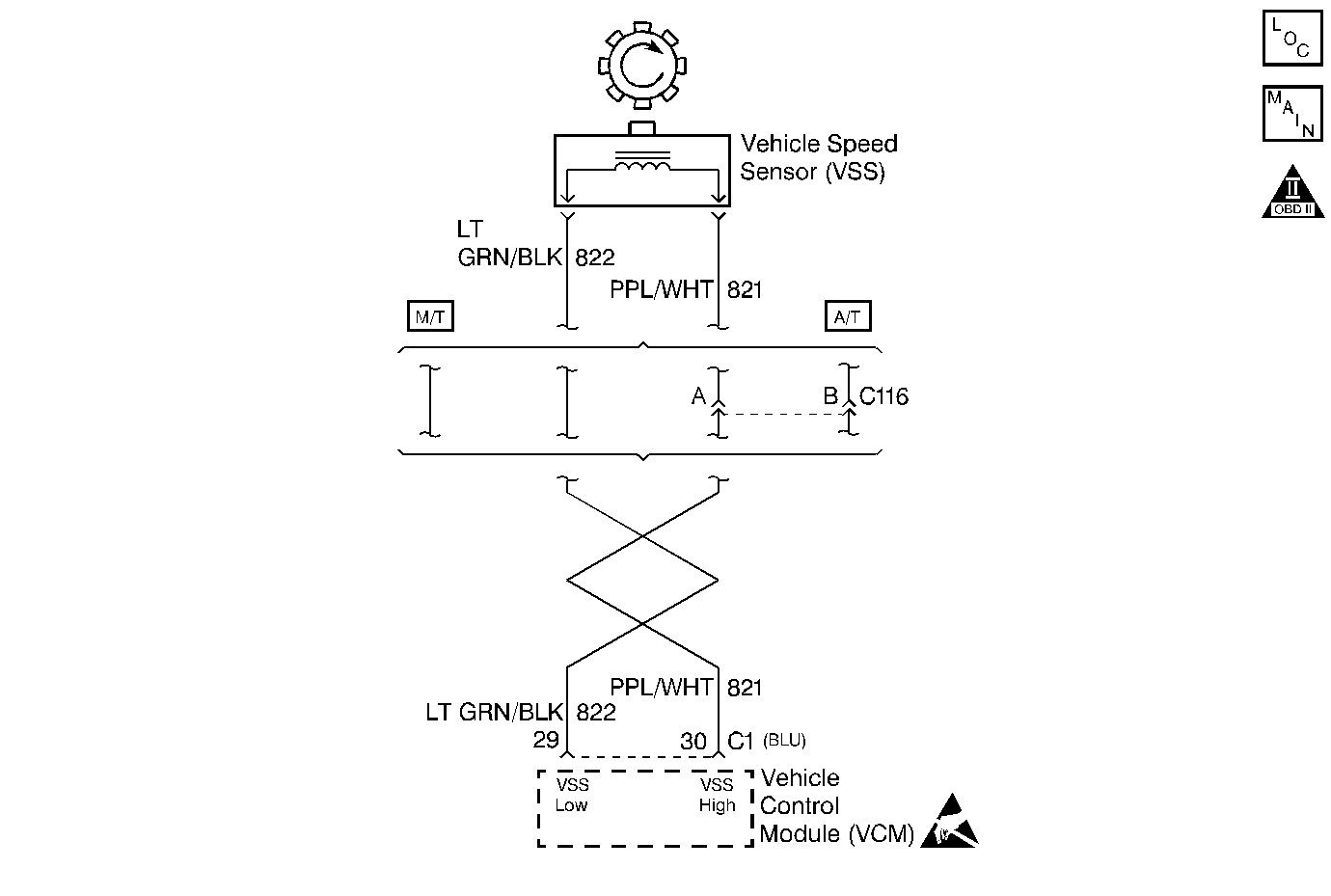
Circuit Description
The Vehicle Speed Sensor (VSS) circuit is of the magnetic induction type. The gear teeth are pressed on the outside diameter of the output shaft assembly. The gear teeth induce an alternating current in the sensor as the shaft rotates. The signal goes directly to the VCM. This pulsing action takes place about 40 times per revolution of output shaft of transmission. The VCM calculates the vehicle speed based on the time between pulses. This is a type A DTC.
Conditions for Setting the DTC
| • | No MAP DTCs |
| • | The throttle angle is below 3.125% |
| • | The engine coolant temperature is above 60°C |
| • | The engine speed is between 1400 and 4400 RPM |
| • | The MAP is below 20 kPa |
| • | All of the conditions have been met for 5 seconds |
Action Taken When The DTC Sets
| • | The VCM turns the MIL ON when this DTC is reported and one failure has occurred. |
| • | The VCM records the operating conditions at the time the Diagnostic Fails. Freeze Frame and Failure Records store this information. |
Conditions for Clearing the MIL/DTC
The VCM turns OFF the MIL after 3 consecutive driving trips without a fault condition present. A history DTC will clear if no fault conditions have been detected for 40 warm-up cycles (the coolant temperature has risen 22°C (40°F) from the start-up coolant temperature and the engine coolant temperature exceeds 71°C (160°F) during that same ignition cycle) or the scan tool clearing feature has been used.
Diagnostic Aids
Check proper calibration for the speedometer.
Test Description
The numbers below refer to the step numbers in the diagnostic table.
-
This step determines if the DTC P0500 is the result of a hard failure or an intermittent condition.
-
This step checks the wiring, the connections, the VCM, and the VSS.
Step | Action | Value(s) | Yes | No |
|---|---|---|---|---|
1 |
Important: Before clearing the DTCs, use the scan tool in order to record the Freeze Frame and the Failure Records for reference. This data will be lost when the Clear Info function is used. Was the Powertrain On-Board Diagnostic (OBD) System Check performed? | -- | ||
Is the voltage constant? | -- | |||
3 | Does the voltage vary? | -- | Go to Diagnostic Aids | |
4 | Does the voltmeter read NO voltage? | -- | ||
5 |
Does the voltage vary with the RPM? | -- | ||
6 | Replace the Vehicle Speed Sensor. Refer to Transmission. Is the action complete? | -- | -- | |
7 |
Was a problem found? | -- | ||
8 |
Was a problem found? | -- | ||
9 | Repair the connection as necessary. Is the action complete? | -- | -- | |
10 | Repair the open or short as necessary. Refer to Wiring Repair in Engine Electrical. Is the action complete? | -- | -- | |
11 | Replace the VCM. Important: When replacing the VCM, the new VCM will need to be programmed. Refer to VCM Replacement/Programming . Is the action complete? | -- | -- | |
12 |
Does the scan tool indicate that this diagnostic ran and passed? | -- | ||
13 | Use the scan tool in order to display the Capture Info and the Review Info. Are there any DTCs displayed that have not been diagnosed? | -- | Go to the applicable DTC table | System OK |
