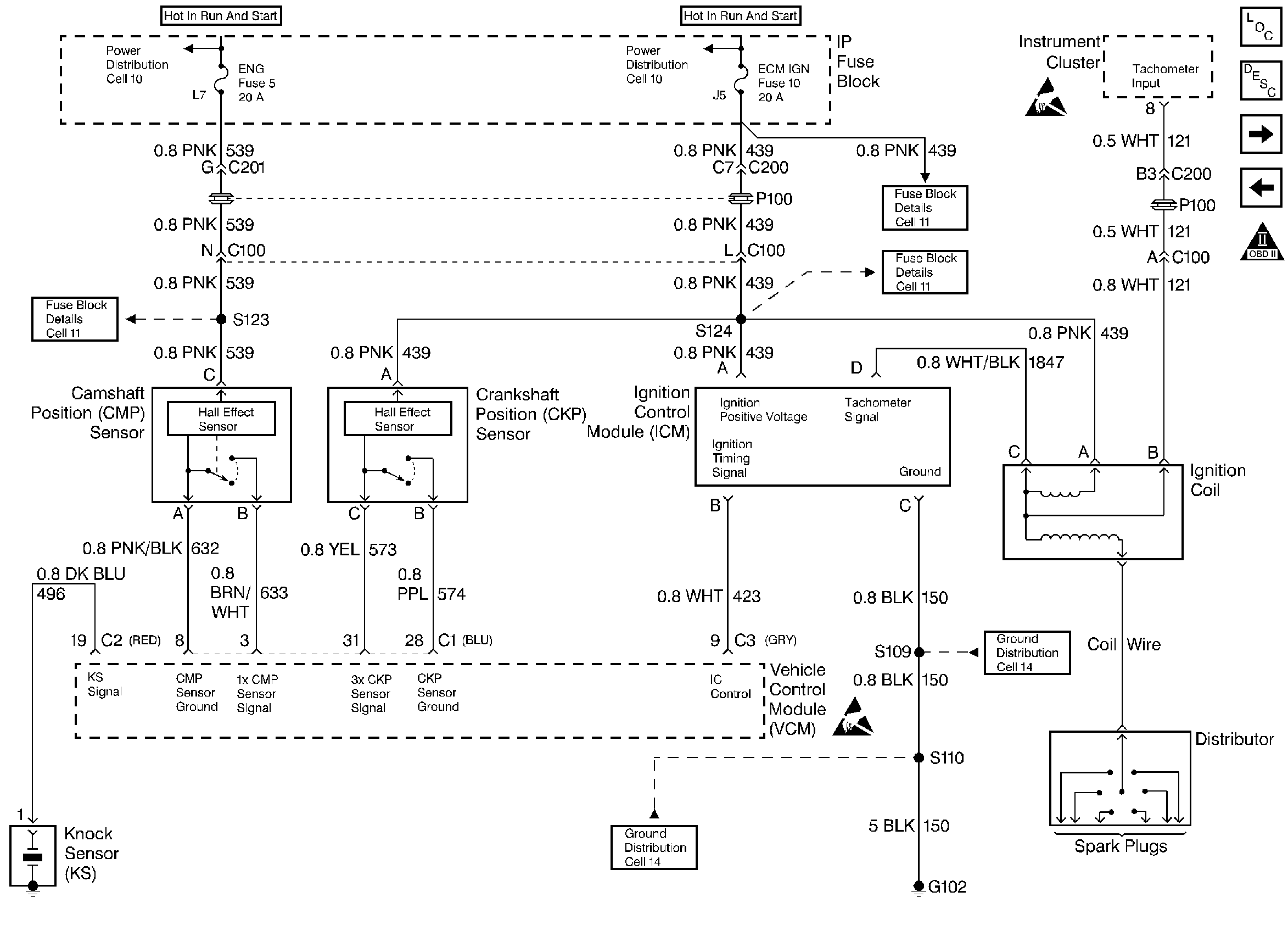
Refer to
CMP, CKP, ICM, and the Ignition Coil

.
Circuit Description
The diagnosis for an engine that cranks but does not run must have three elements present before proceeding with the diagnostic table. The following conditions must exist:
| • | The battery must be adequately charged. |
| • | The engine cranking speed must be sufficient. |
| • | There must be an adequate amount of fuel in the fuel tank. |
Diagnostic Aids
If no trouble is found in the fuel pump circuit or the ignition system and the cause of an Engine Cranks But Will Not Run has not been found, check for the following conditions:
| • | Fouled spark plugs |
| • | An EGR valve stuck open |
| • | Low fuel pressure. Refer to Fuel System Pressure Test . |
| • | Water or foreign material in the fuel system |
| • | A grounded Ignition Control (IC) signal circuit may cause a No Start or a Start then Stall condition |
| • | A Basic engine problem |
The VCM has integrated IC circuits that are fault protected; therefore, if a circuit has failed, the failure may not damage the integrated IC. If that is the case, the IC will keep the circuit open until the fault in the circuit has been corrected.
When the fault has been corrected, reinstall the VCM. Check the circuit. Replace the VCM only if the circuit is still inoperative.
Test Description
The numbers below refer to the step numbers on the diagnostic tables.
-
If the signal is over 2.5 volts, the engine may be in the clear flood mode which will cause starting problems.
-
If the engine coolant sensor is below -30°C, the VCM provides fuel for this extremely cold temperature which will severely flood the engine.
-
This step checks the ignition feed circuit to the injectors.
-
Voltage at the spark plug is checked using the spark plug tester tool J 26792 . No spark indicates a basic ignition problem.
-
This test determines if there is fuel pressure at the fuel injection unit and holding steady.
Step | Action | Value(s) | Yes | No |
|---|---|---|---|---|
1 |
Important: Before clearing the DTCs, use the scan tool to record the Freeze Frame and the Failure Records for reference. This data will be lost when the Clear Info function is used. Was the Powertrain On-Board Diagnostic (OBD) System Check performed? | -- | ||
With the throttle closed is the TP sensor over the specified value? | 2.5V | Go to DTC P0123 Throttle Position (TP) Sensor Circuit High Voltage | ||
Monitor the ECT sensor on the scan tool. Is the ECT sensor below the specified value? | -30°C | Go to DTC P0118 Engine Coolant Temperature (ECT) Sensor Circuit High Voltage | ||
4 |
Does the fuel pump operate for 2 seconds? | -- | ||
Is the test light ON? | -- | |||
Is the spark present? | -- | |||
Is the fuel pressure within the specified range? | 415-455 kPa (60-66 psi | |||
8 | Repair the injector ignition feed circuit. Refer to Wiring Repairs in Engine Electrical. Is the action complete? | -- | -- | |
9 |
Does the engine start and continue to run? | -- | ||
10 |
Are there any DTCs displayed? | -- | Go to The Applicable DTC Table | |
11 | Use the scan tool in order to select the Capture info and the Review info. Are there any DTCs displayed that have not been diagnosed? | -- | Go to The Applicable DTC Table | System OK |
