For 1990-2009 cars only
Removal Procedure
Notice: Do not open the DERM case for any reason. Touching the connector pins, or the soldered components may cause electrostatic discharge damage. Replacement is the only way to repair a malfunctioning DERM.
- Disable to Supplemental Restraint System (SRS). Refer to Disabling the SRS .
- Remove the right hand sound insulator. Refer to Instrument Panel Replacement in Interior Trim Section 10A4.
- Remove the right hand sill plate. Refer to Sill Plate Replacement in Interior Trim Section 10A4.
- Remove the right hand cowl kick panel. Refer to Cowl Kick Panel Trim Replacement in Interior Trim Section 10A4.
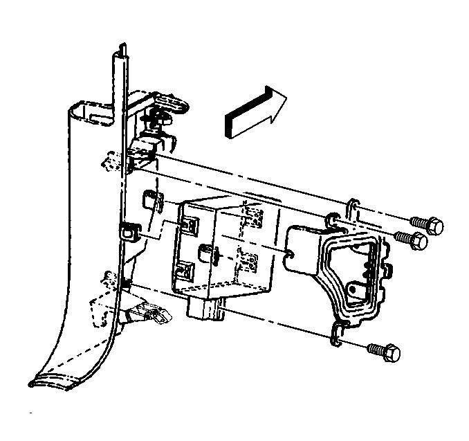
- Remove the DERM from the mounting bracket.
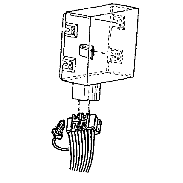
- Disconnect the connector lock.
- Disconnect the DERM electrical connector from the DERM.


Installation Procedure
- Connect the DERM electrical connector to the DERM.
- Connect the connector lock.
- Install the DERM to the mounting bracket.
- Install the right hand cowl kick panel. Refer to Cowl kIick Panel Trim Replacement in Interior Trim Section 10A4.
- Connect the right hand sill plate. Refer to Sill Plate Replacement in Interior Trim Section 10A4.
- Connect the right hand sound insulator. Refer to Instrument Panel Replacement in Interior Trim Section 10A4.
- Enable the Supplemental Restraint System (SRS). Refer to Enabling the SRS .


Tighten
Tighten nuts to 3 N·m (25 lb in). Tighten
screws 1 N·m (5 lb in).
