Removal Procedure
- Disable the SIR system. Refer to Disabling the SIR System in SIR.
- Disconnect the negative battery cable. Refer to Battery Negative Cable Disconnection and Connection in Engine Electrical.
- Remove left insulator panel. Refer to Instrument Panel Insulator Panel Replacement - Left Side .
- Remove right insulator panel. Refer to Instrument Panel Insulator Panel Replacement - Right Side .
- Remove the IP outer trim covers. Refer to Instrument Panel Outer Trim Cover Replacement .
- Remove the IP upper trim pad. Refer to Instrument Panel Upper Trim Pad Replacement .
- Remove the center console. Refer to Front Floor Console Replacement .
- Remove the radio. Refer to Radio Replacement in Entertainment.
- Remove the HVAC control module assembly. Refer to HVAC Control Module Replacement in HVAC Systems Automatic.
- Remove the drivers information center. Refer to Driver Information Center Module Replacement .
- Remove the knee bolster. Refer to Knee Bolster Replacement .
- Remove the knee bolster brackets. Refer to Knee Bolster Bracket Replacement .
- Remove the fasteners securing the steering column to the IP carrier, lower and position the column out of the way. Refer to Steering Column Replacement in Steering.
- Remove the IP cluster. Refer to Instrument Cluster Replacement .
- Remove the valet switch. Refer to Rear Compartment Lid Valet Lock Out Switch Replacement .
- Remove the IP storage compartment. Refer to Instrument Panel Storage Compartment Replacement .
- Disconnect the center IP to body electrical harness connector.
- Disconnect the right IP to body electrical harness connector.
- Disconnect the left IP to body electrical harness connector.
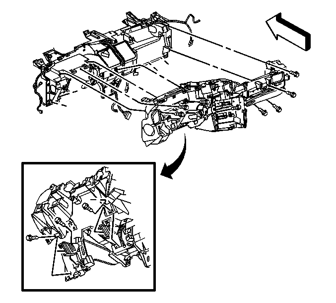
- Remove fasteners securing the IP retainer to IP carrier.
- Remove the IP retainer from the carrier, feed wiring through openings as necessary.
- If the IP retainer is to be replaced, transfer all necessary components.
Caution: This vehicle is equipped with a Supplemental Inflatable Restraint (SIR) System. Failure to follow the correct procedure could cause the following conditions:
• Air bag deployment • Personal injury • Unnecessary SIR system repairs • Refer to SIR Component Views in order to determine if you are performing service on or near the SIR components or the SIR wiring. • If you are performing service on or near the SIR components or the SIR wiring, disable the SIR system. Refer to Disabling the SIR System.
Installation Procedure
- Position the IP retainer to the carrier, feeding the wiring through the openings as removed.
- Install the IP retainer fasteners in order to secure the IP retainer to the carrier.
- Connect the left IP to body electrical harness connector.
- Connect the right IP to body electrical harness connector.
- Connect the center IP to body electrical harness connector.
- Install the IP storage compartment. Refer to Instrument Panel Storage Compartment Replacement .
- Install the valet switch. Refer to Rear Compartment Lid Valet Lock Out Switch Replacement .
- Install the IP cluster. Refer to Instrument Cluster Replacement .
- Install the steering column. Refer to Steering Column Replacement in Steering Wheel and Column-Tilt.
- Install the knee bolster brackets. Refer to Knee Bolster Bracket Replacement .
- Install the knee bolster. Refer to Knee Bolster Replacement .
- Install the drivers information center. Refer to Driver Information Center Module Replacement .
- Install the HVAC control module assembly. Refer to HVAC Control Module Replacement in HVAC Systems Automatic.
- Install the radio. Refer to Radio Replacement in Entertainment.
- Install the center console. Refer to Front Floor Console Replacement .
- Install the IP upper trim pad. Refer to Instrument Panel Upper Trim Pad Replacement .
- Install the IP outer trim covers. Refer to Instrument Panel Outer Trim Cover Replacement .
- Install right insulator panel. Refer to Instrument Panel Insulator Panel Replacement - Right Side .
- Install left insulator panel. Refer to Instrument Panel Insulator Panel Replacement - Left Side .
- Connect the negative battery cable. Refer to Battery Negative Cable Disconnection and Connection in Engine Electrical.
- Enable the SIR system. Refer to Enabling the SIR System in SIR.
Notice: Use the correct fastener in the correct location. Replacement fasteners must be the correct part number for that application. Fasteners requiring replacement or fasteners requiring the use of thread locking compound or sealant are identified in the service procedure. Do not use paints, lubricants, or corrosion inhibitors on fasteners or fastener joint surfaces unless specified. These coatings affect fastener torque and joint clamping force and may damage the fastener. Use the correct tightening sequence and specifications when installing fasteners in order to avoid damage to parts and systems.
Tighten
Tighten the fasteners to 2 N·m (18 lb in).
