Removal Procedure
- Raise and support the vehicle. Refer to Lifting and Jacking the Vehicle.
- Remove the rear wheels. Refer to Tire and Wheel Removal and Installation.
- Remove the intermediate exhaust assembly. Refer to Exhaust Crossover Pipe Replacement.
- Remove the propeller shaft heat shield. Refer to Exhaust Heat Shield Replacement - Center.
- Remove the propeller shaft. Refer to Propeller Shaft Replacement.
- Remove the fuel tank heat shield. Refer to Fuel Tank Heat Shield Replacement.
- Lower the vehicle to the ground.
- Remove the park brake cable adjustment bolt cover trim (1).
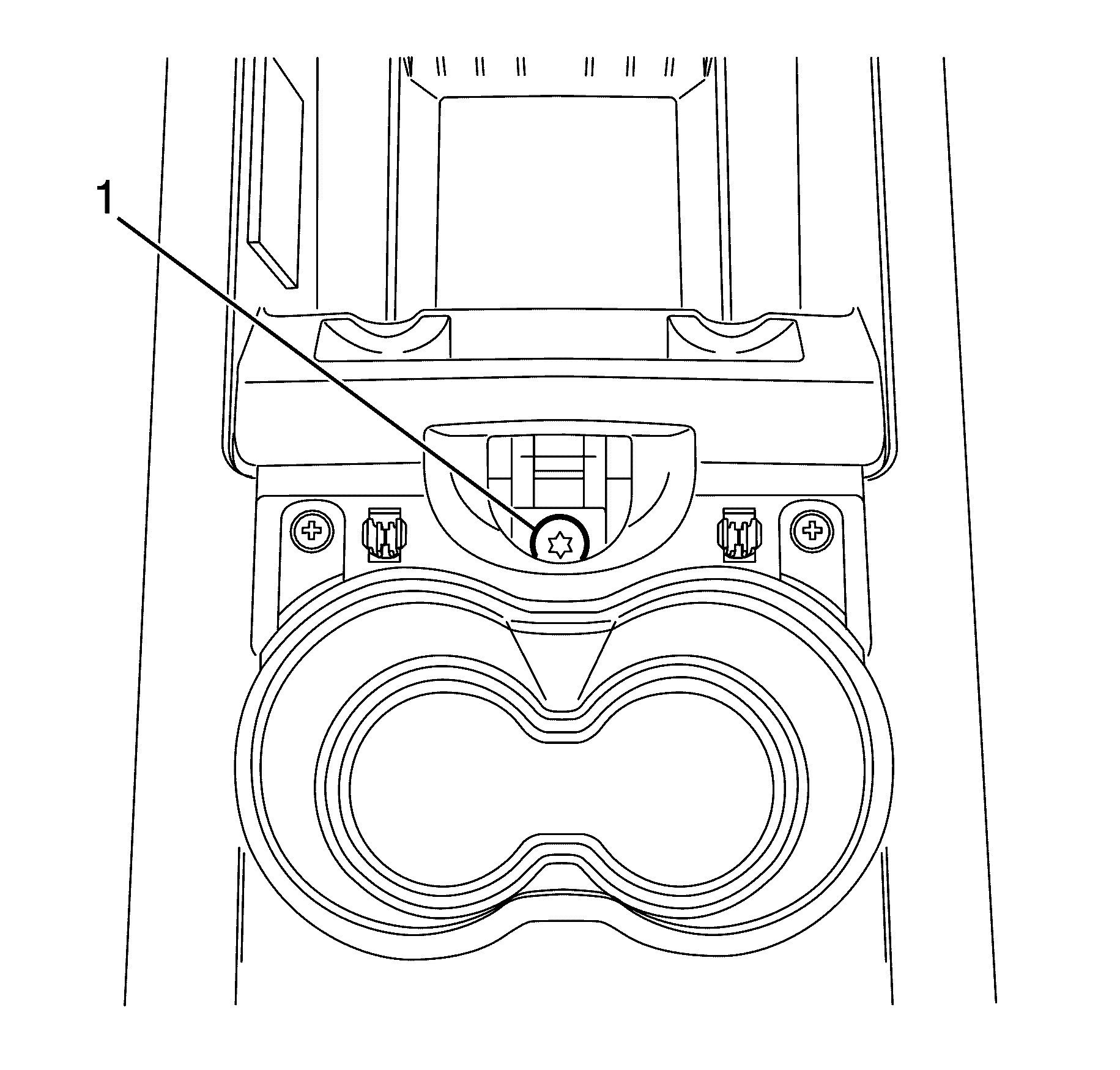
- Loosen the park brake cable adjustment bolt (1) all the way to allow maximum slack in the rear park brake cables.
- Raise the vehicle.
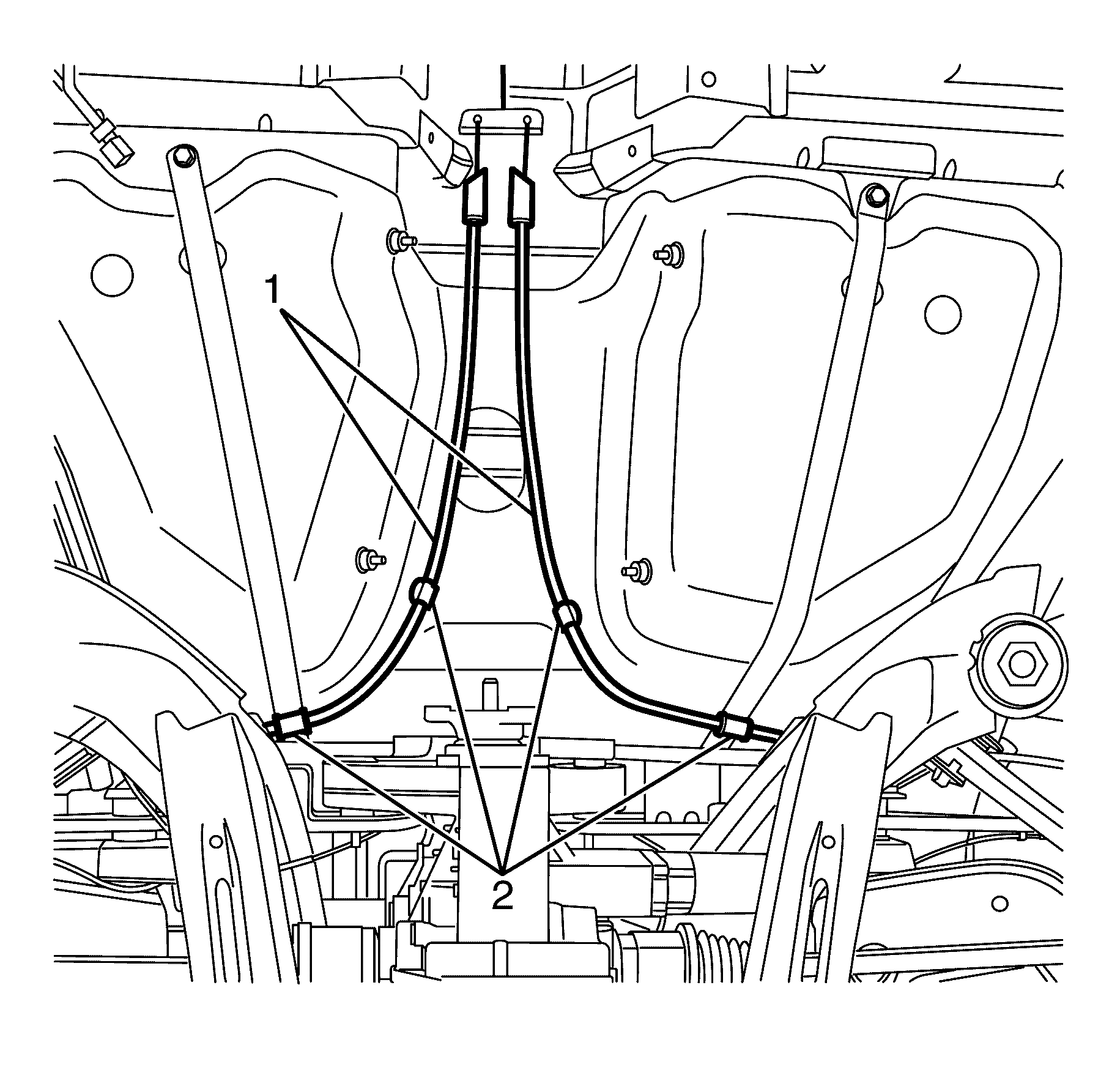
- Detach the park brake cables (1) from the underbody park brake cable retaining clips (2).
- Remove the rear inner cables (1) from the front park brake cable and equalizer bracket assembly (2).
- Remove the outer cable (4) from the vehicle underbody bracket (3).
- Remove the outer cable (4) from the rear knuckle (3).
- Detach the rear park brake cable and clevis (1) from the park brake actuator (2).
Warning: Refer to Safety Glasses Warning in the Preface section.
Warning: Refer to Brake Dust Warning in the Preface section.
Danger: To avoid any vehicle damage, serious personal injury or death when major components are removed from the vehicle and the vehicle is supported by a hoist, support the vehicle with jack stands at the opposite end from which the components are being removed and strap the vehicle to the hoist.
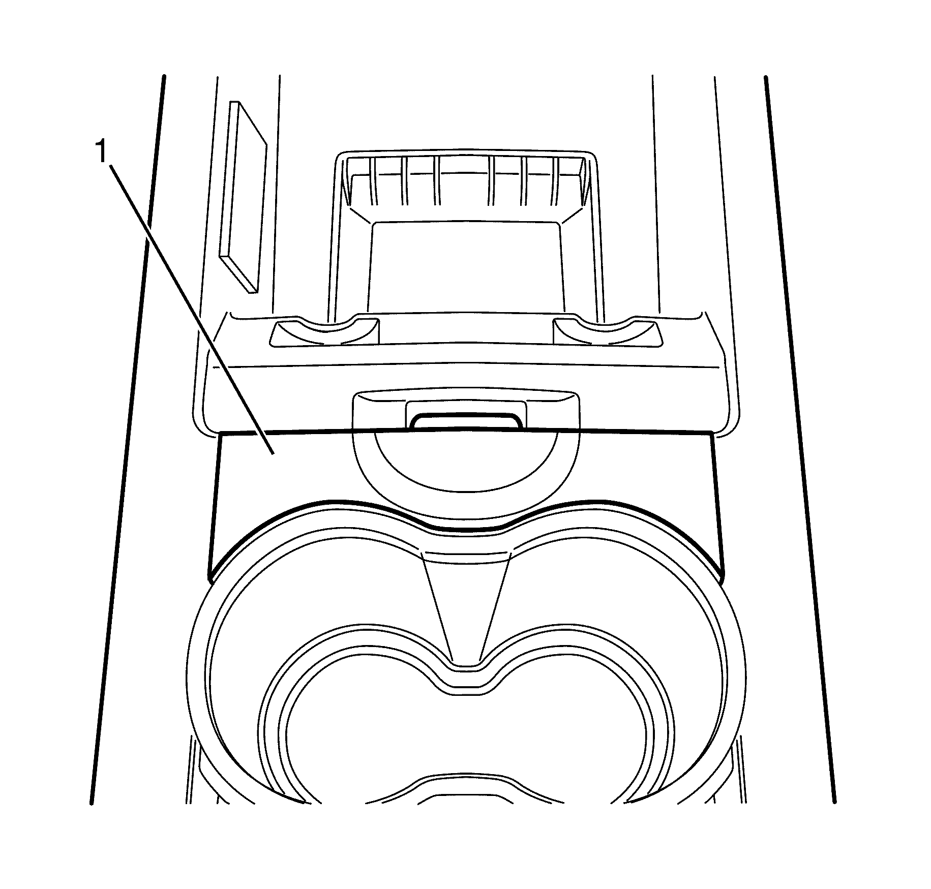
Note: The park brake cable adjustment bolt cover trim (1) is retained by 2 clips. Gently pry upwards with fingers at the front floor console armrest latch to remove.
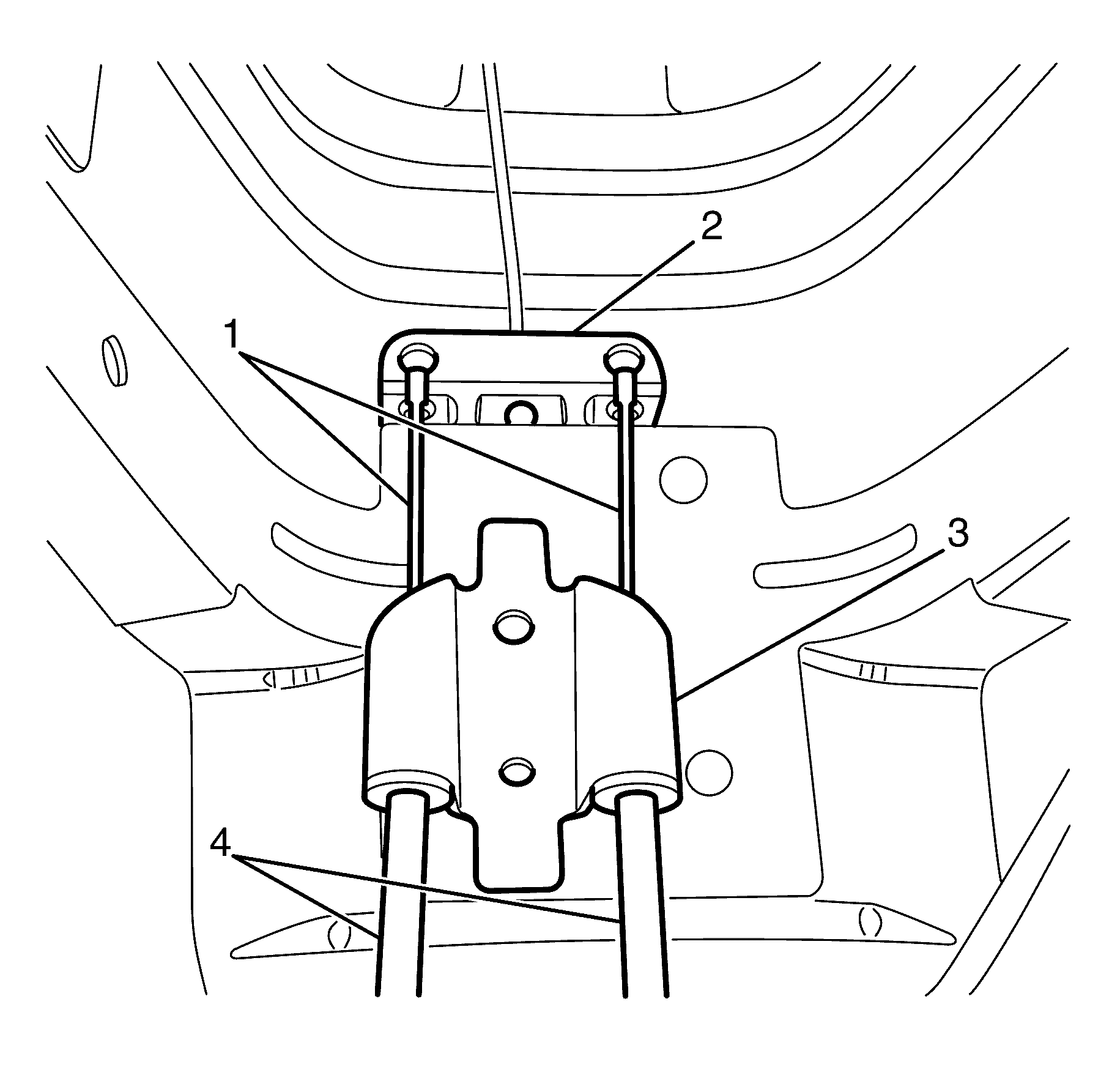
Note: Wrap a workshop cloth around the rear inner cable (1) to protect it from damage. Using pliers, pull the rear inner cable (1) forward and upwards to release the ball nipple from the front park brake cable and equalizer bracket assembly (2).
Note: Remove the outer cable (4) from the vehicle underbody bracket (3) by pulling the outer cable (4) rearward.
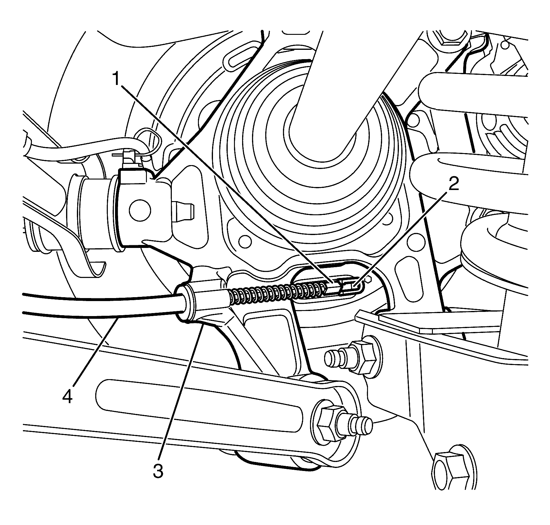
Note: Remove the outer cable (4) from the rear knuckle (3) by pulling the outer cable (4) forward.
Installation Procedure
- Attach the rear park brake cable and clevis (1) to the park brake actuator (2).
- Install the rear park brake cable (4) into the rear knuckle (3).
- Install the outer cable (4) to the vehicle underbody bracket (3).
- Install the rear inner cables (1) to the front park brake cable and equalizer bracket assembly (2).
- Attach the park brake cables (1) to the underbody park brake cable retaining clips (2).
- Adjust the park brake. Refer to Park Brake Adjustment.
- Cycle the park brake lever 2-3 times to make sure that the park brake cable retainers are seated.
- Install the fuel tank heat shield. Refer to Fuel Tank Heat Shield Replacement.
- Install the propeller shaft. Refer to Propeller Shaft Replacement.
- Install the propeller shaft heat shield. Refer to Exhaust Heat Shield Replacement - Center.
- Install the intermediate exhaust assembly. Refer to Exhaust Crossover Pipe Replacement.
- Install the rear wheels. Refer to Tire and Wheel Removal and Installation.
- Lower the vehicle to the ground.
Warning: Refer to Safety Glasses Warning in the Preface section.
Warning: Refer to Brake Dust Warning in the Preface section.

Danger: To avoid any vehicle damage, serious personal injury or death when major components are removed from the vehicle and the vehicle is supported by a hoist, support the vehicle with jack stands at the opposite end from which the components are being removed and strap the vehicle to the hoist.
Make sure that the rear park brake cables (4) are properly seated.

Make sure that the outer cables (4) are properly seated in the vehicle underbody bracket (3).
Note: Wrap a workshop cloth around the rear inner cable (1) to protect it from damage. Using pliers, pull the rear inner cable (1) forward and downwards to install the ball nipple to the front park brake cable and equalizer bracket assembly (2).

