For 1990-2009 cars only
Tools Required
J 45059 Angle Meter
Removal Procedure
- Raise and support the vehicle. Refer to Lifting and Jacking the Vehicle .
- Remove the rear suspension support. Refer to Rear Support Replacement .
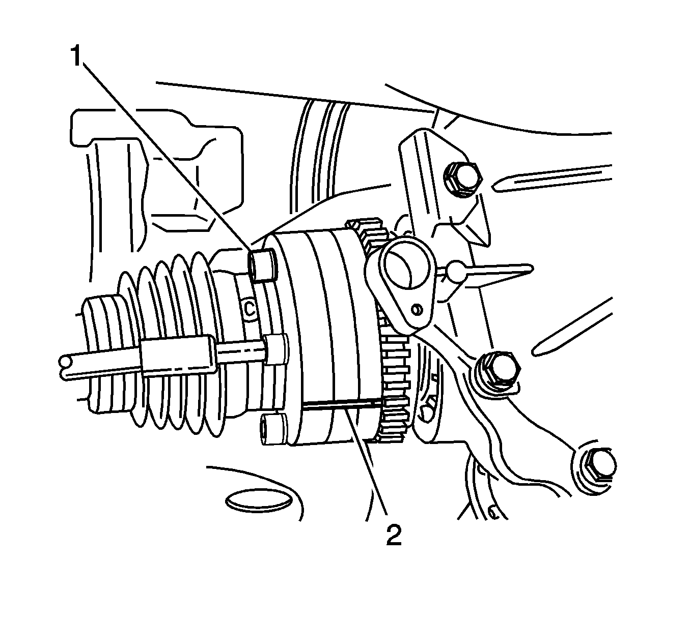
- Mark the relationship of the inner constant velocity joints to the axle shafts (2).
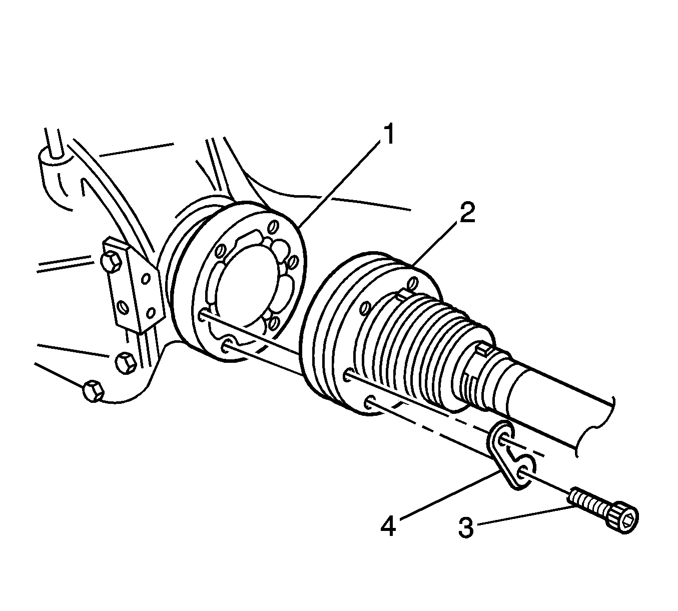
- Remove the inner drive shaft constant velocity joint bolts (3) and retainer plates (4) . Support the drive shafts so they do not hang.
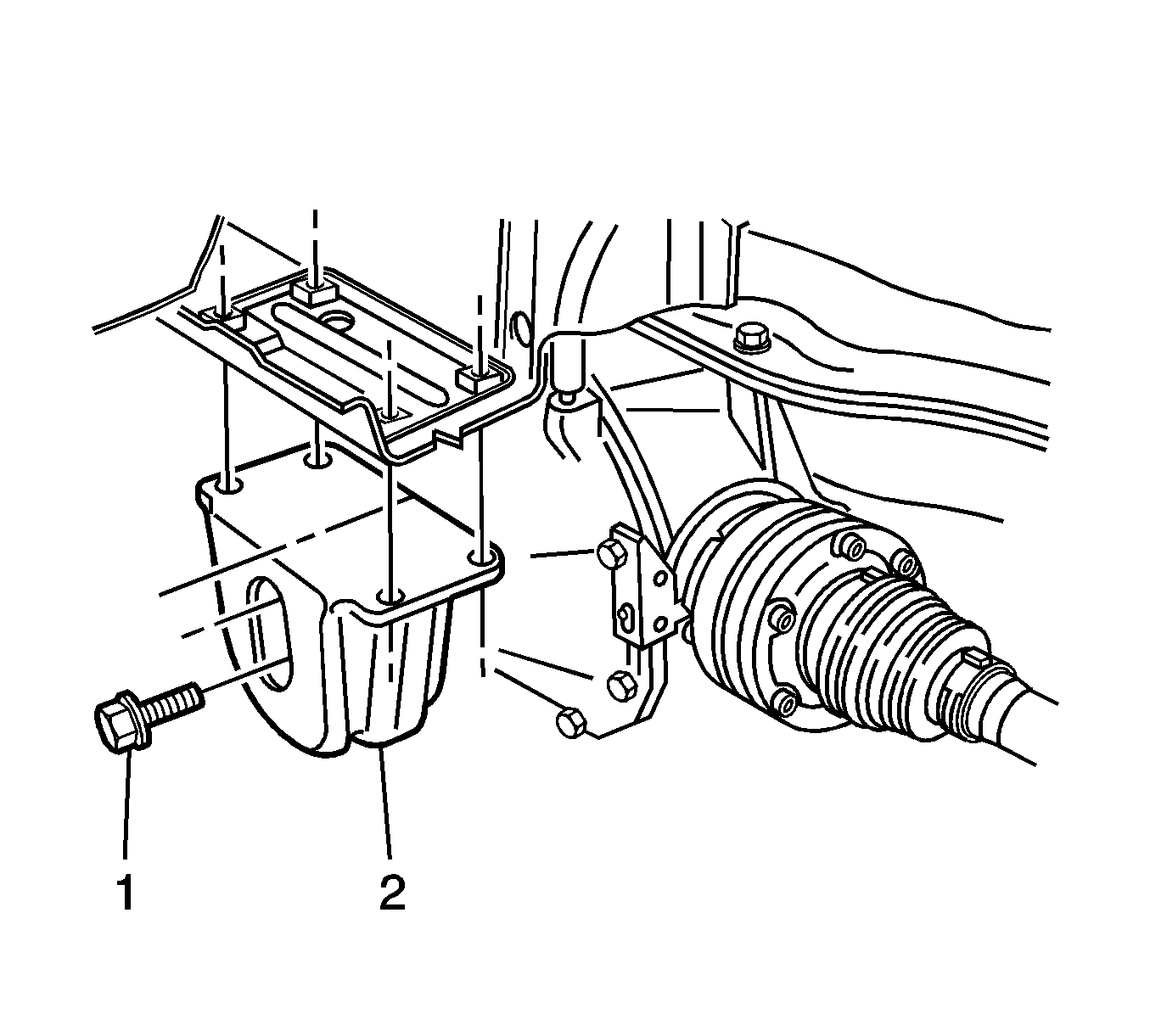
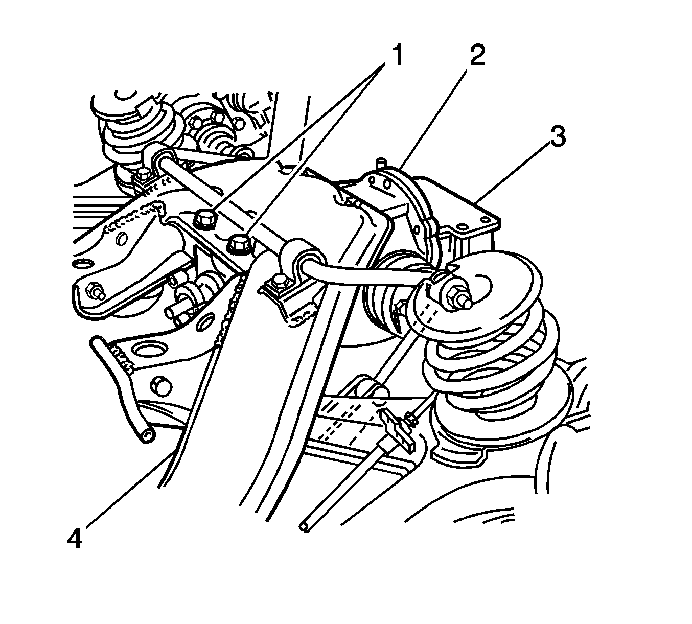
- Remove the rear differential mount bolts (1) from the differential cover.
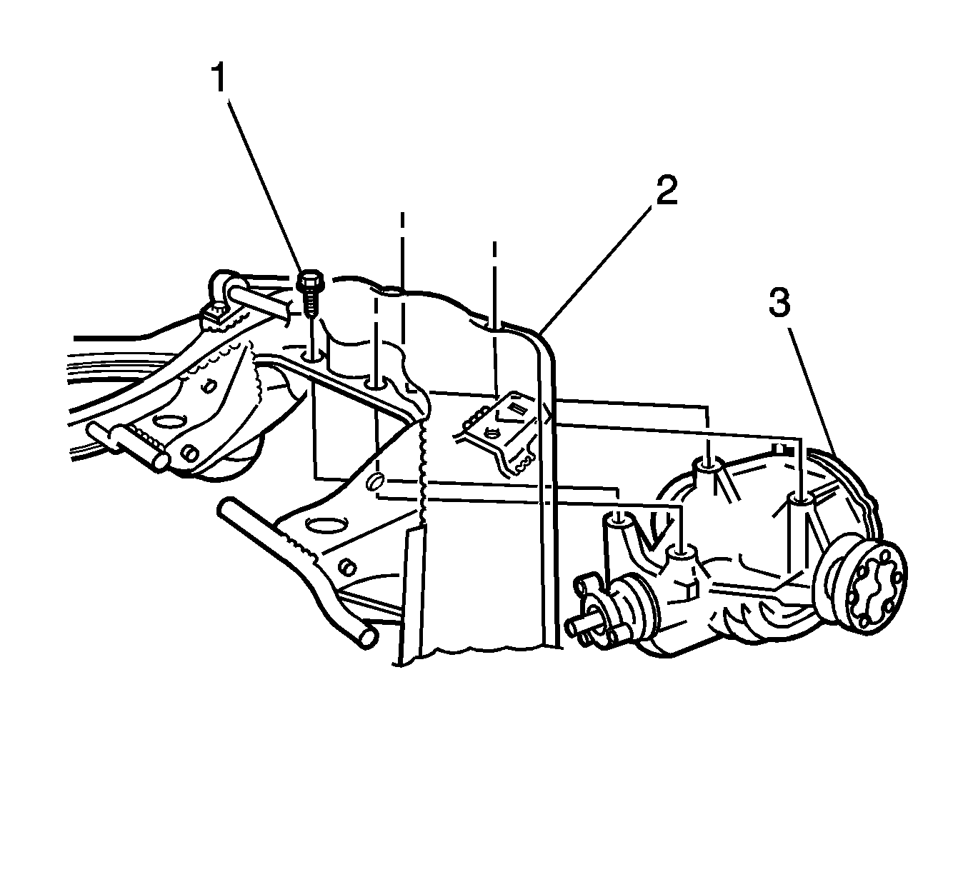
- Remove the differential carrier attach bolts from the crossmember.
- Remove the differential carrier (3).
Installation Procedure
- Using 4 new bolts (1) install in the cross-member to the differential carrier bolts.
- Tighten the bolts to 90 N·m (66 lb ft).
- Using the J 45059 , tighten the bolts an additional 68 degrees.
- Align the marks (2) on the inner constant velocity joint and the axle shaft.
- Install the inner constant velocity joints to the axle shaft bolts and retaining plates.
- Tighten bolts (1) to 50 N·m (37 lb ft).
- Using the J 45059 , tighten the bolts an additional 68 degrees.
- Install the differential rear mount to the differential cover.
- Install the rear suspension support. Refer to Rear Support Replacement in Rear Suspension.
- Lower the vehicle. Refer to Lifting and Jacking the Vehicle In General Information.
Notice: Refer to Fastener Notice in the Preface section.
Tighten

Tighten

Tighten
Tighten the differential rear mount bolts to 95 N·m (70 lb ft).
