Tools Required
| • | CH-46839 Rear Crossmember Centering Tool |
| • | J 45059 Angle Meter |
Removal Procedure
- Raise and support the rear of the vehicle. Refer to Lifting and Jacking the Vehicle in General Information.
- Remove the rear wheels and tires. Refer to Tire and Wheel Removal and Installation in Tires and Wheels.
- Remove the rear exhaust system. Refer to Muffler Replacement in Engine Exhaust.
- Remove the propeller shaft from the rear axle housing. Refer to Two-Piece Propeller Shaft Replacement in Propeller Shaft.
- Disconnect the rear park brake cables from the rear support. Refer to Parking Brake Rear Cable Replacement - Left Side and Parking Brake Rear Cable Replacement - Right Side in Park Brake.
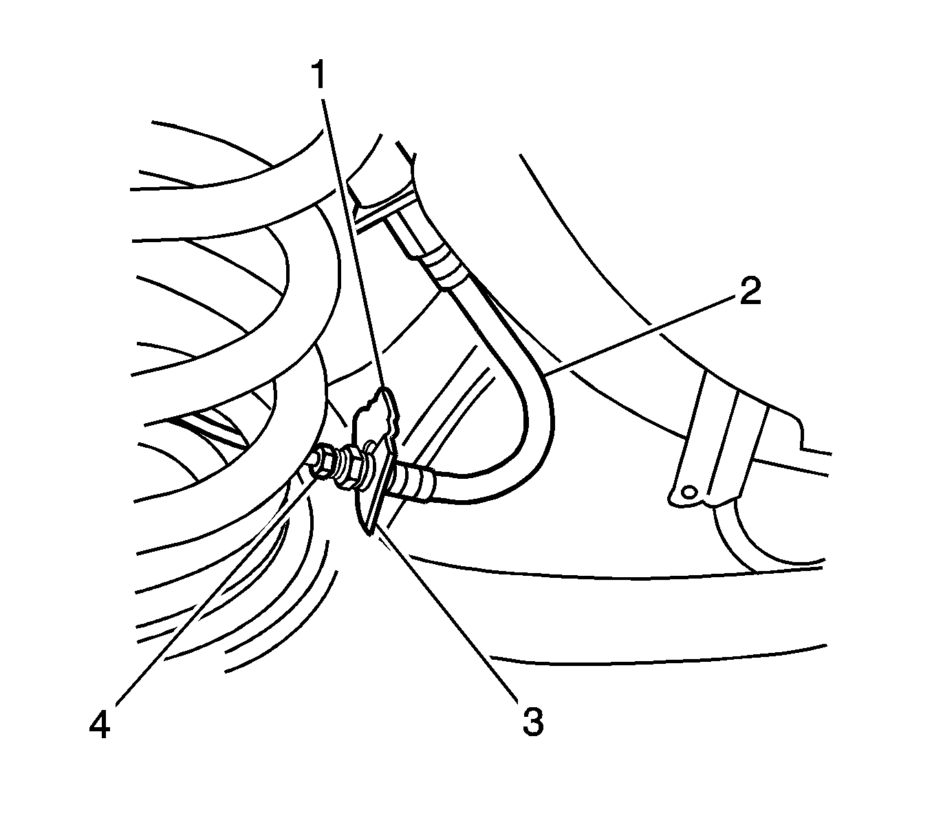
- Disconnect the brake line (4) from the brake hose (2) at the rear suspension control arm bracket (3) and remove the brake hose retaining clip (1).
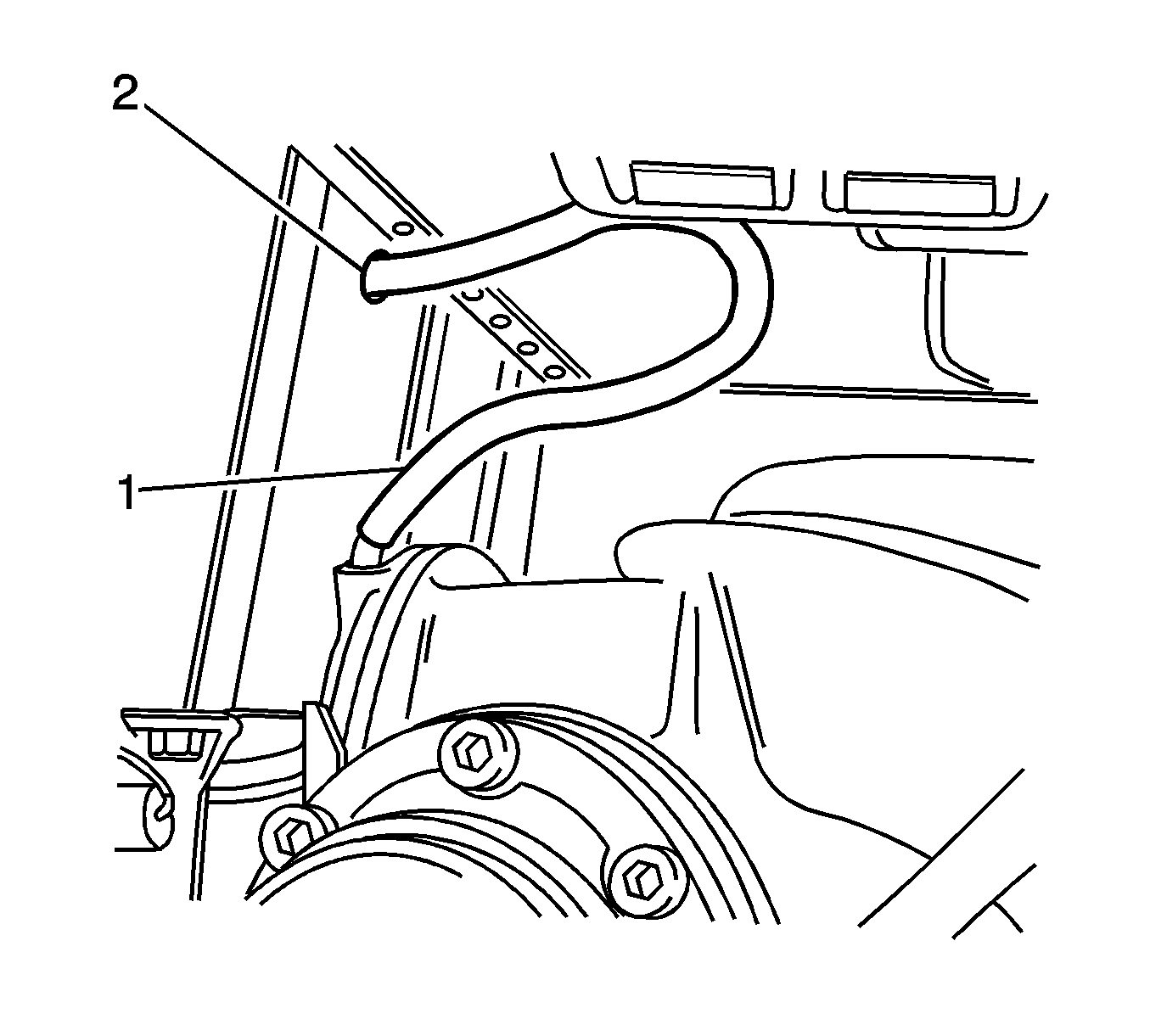
- Pull the differential carrier breather hose (1) out of the hole (2) in the vehicle underbody rear suspension support.
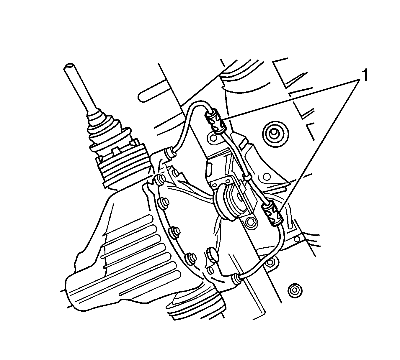
- Remove the ABS sensor lead connectors from the underbody retaining clips (1).
- Disconnect the ABS sensor lead connectors from the body harness connectors.
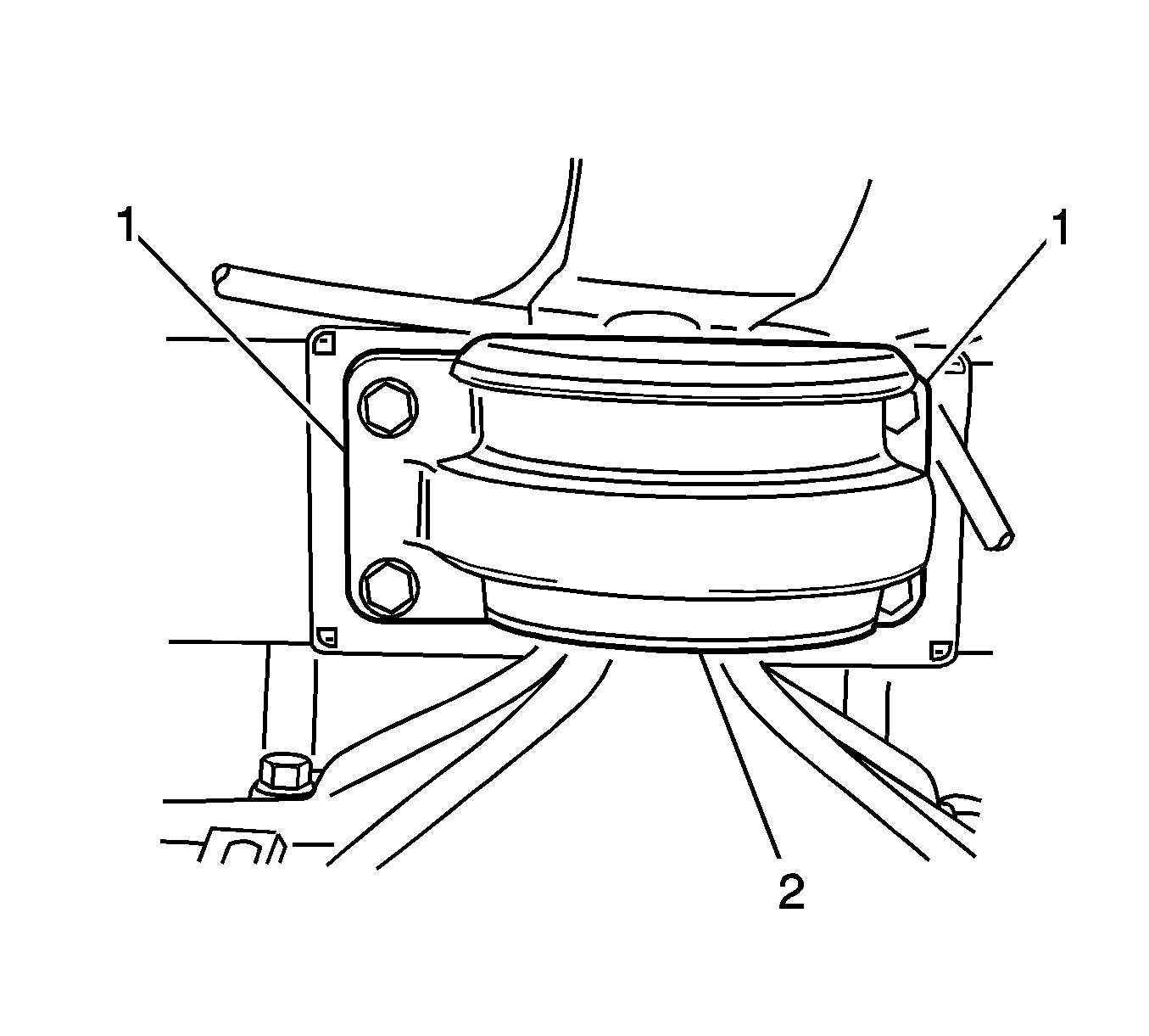
- Using a scriber, mark the rear mount (2) to the vehicle under body location (1), this will assist in the rear suspension support alignment on installation.
- Support the weight of the differential carrier with a floor jack.
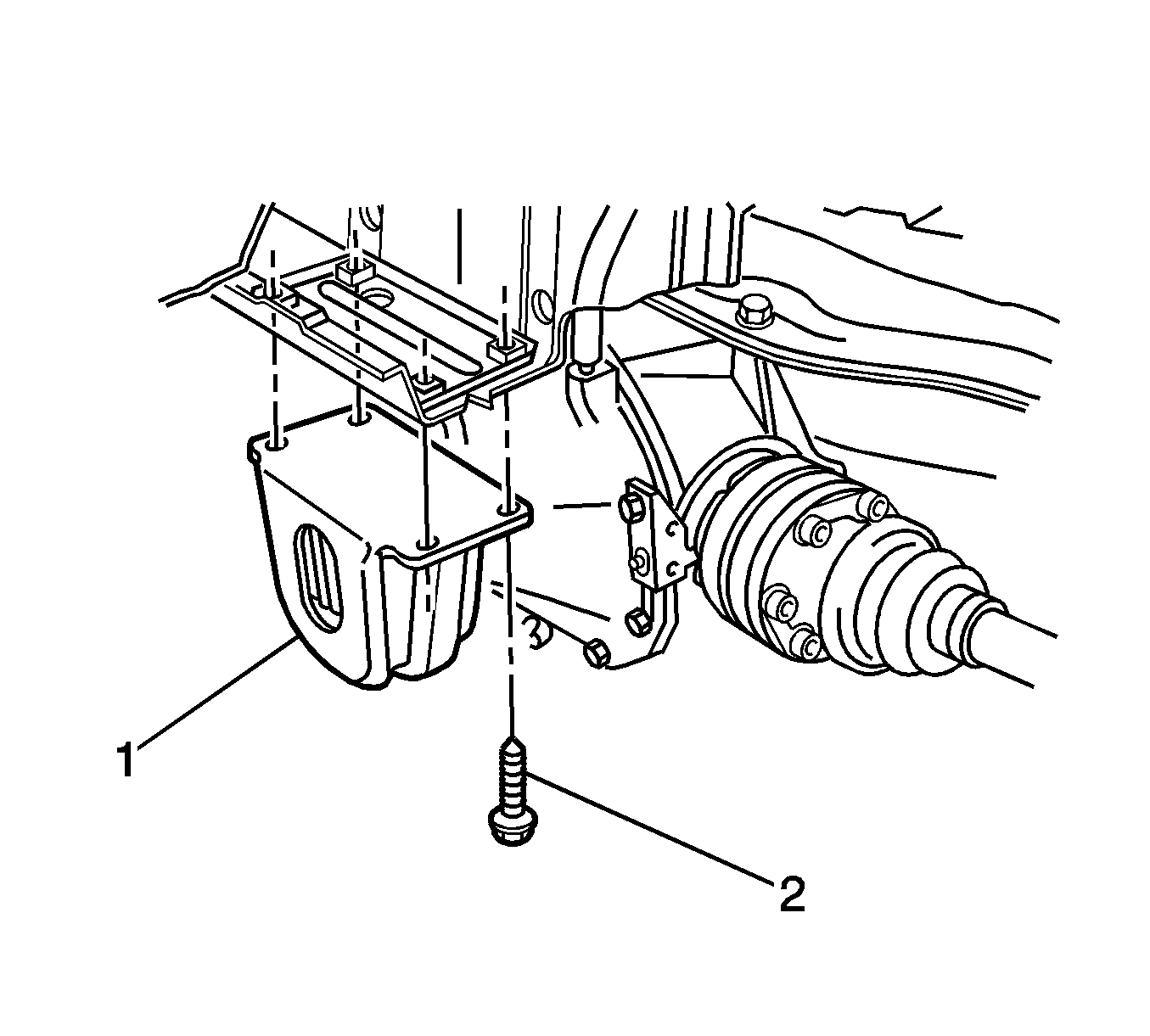
- Remove and discard the 4 rear mount (1) to vehicle underbody attaching bolts (2), and lower the differential carrier and rear suspension assembly by at least 60 mm (2.36 in).
- Remove the rear springs. Refer to Coil Spring Replacement in Rear Suspension.
- Raise the differential carrier and rear suspension support on a floor jack until the rear mount contacts the vehicle underbody.
- Use a floor jack to support the differential carrier and rear suspension support.
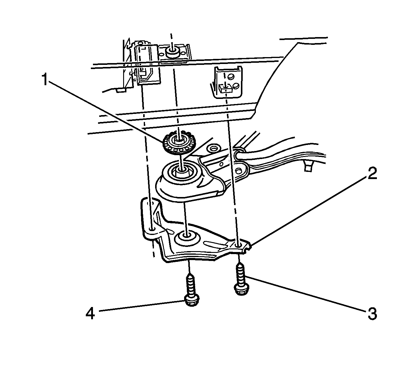
- Remove the 3 brace to underbody bolts (3) from each side of the vehicle.
- Remove and discard the bolt (4) attaching the rear suspension support to the vehicle underbody on each side of the vehicle.
- Remove the braces (2) from the vehicle.
- With the aid of an assistant supporting the front end of the rear suspension support, lower the assembly on the jack and remove from beneath the vehicle.
- Remove the differential carrier and rear suspension support from the jack and support the rear control arms, drive shafts and differential carrier off the ground.
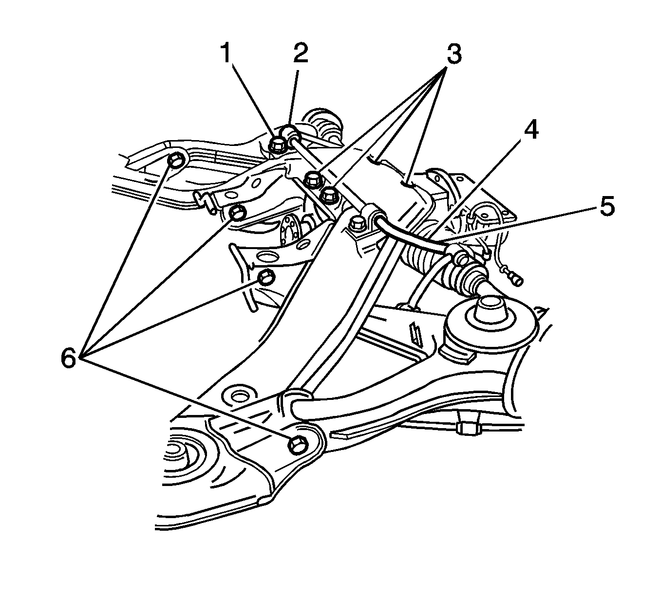
- Remove the stabilizer shaft mounting bracket attaching bolts (1), and remove the mounting brackets (2).
- Remove and discard the differential carrier to rear suspension support attaching bolts (3).
- Remove the rear suspension control arm to rear suspension support attaching bolts and nuts (6), and discard the nuts.
- Disengage the control arms from the rear suspension support.
- Loosen the stabilizer link attaching nuts (5) at each end and on each side to avoid stress on the bushing, and swing the stabilizer shaft (4) back from the rear suspension support.
- Lift up and remove the rear suspension support.
Important: Make sure to plug the open ends of both pipes and hoses to prevent unnecessary fluid loss and/or foreign matter entry.
Installation Procedure
- Install the rear suspension support over the differential carrier and rear control arms.
- Assemble the rear control arms to the rear suspension support brackets and install the attaching bolts and new self locking nuts (6).
- Align the rear suspension support and differential carrier mounting holes and install new attaching bolts (3).
- Position the stabilizer shaft (4) onto the rear suspension support, with the insulators located over the mounting points.
- Engage the brackets (2) into the mounting points and install over the insulators.
- Install the bolts (1) attaching the stabilizer shaft mounting brackets (2) to the rear suspension support.
- With the aid of 2 assistants, place the differential carrier and rear suspension support onto a floor jack.
- Position the rear suspension support assembly under the vehicle, raise with the jack and, with the aid of the assistants, guide the rear suspension support front mounting points into position.
- Make sure the isolating rubber (1) is at the top of each rear suspension support front mount bushing and then raise the rear suspension support into place.
- Install the rear suspension support mounting braces (2), and the attaching bolts (3).
- Install the new front mounting bolts (4) to the rear suspension support.
- Lower the differential carrier and rear suspension support on the floor jack and safety stands.
- Install the rear springs. Refer to Coil Spring Replacement in Rear Suspension.
- Raise the rear suspension support assembly until the rear mount contacts the vehicle underbody.
- Align the rear mount (1) with the marks on the underbody made on disassembly.
- Install 4 new bolts (2) attaching the rear mount (1) to the vehicle underbody.
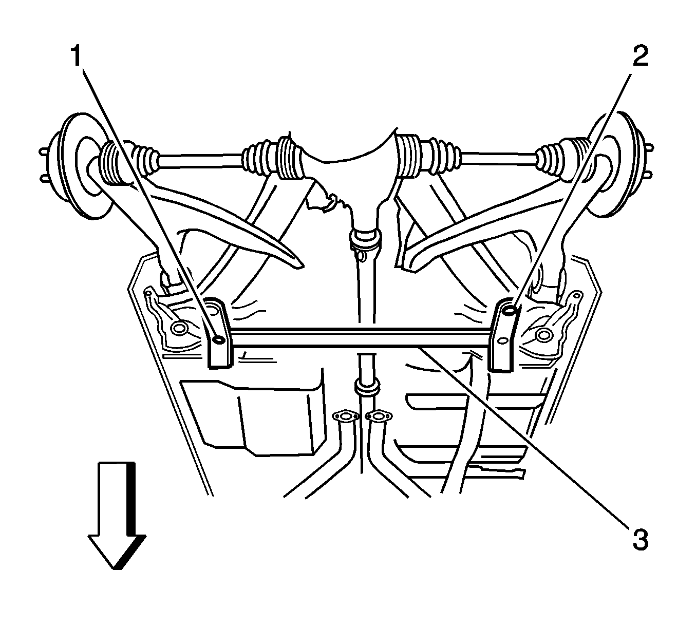
- Fit the CH-46839 to the underbody.
- The rear crossmember centering tool (3) locates into 19 mm (0.74 in) diameter body datum holes (1) positioned forward of the rear suspension support.
- With the aid of an assistant, position the rear suspension support until the location pins (2) of the rear crossmember centering tool (3) engage the alignment holes on the rear suspension support assembly.
- Locate the brace to underbody bolts (4).
- Tighten the brace to underbody bolts to 125 N·m (92 lb ft).
- Use the J 45059 in order to tighten the bolts an additional 40 degrees.
- Locate the rear differential mount attaching bolts (2).
- Tighten the bolts to 35 N·m (26 lb ft).
- Use the J 45059 in order to tighten the bolts an additional 60 degrees.
- Locate the bolts (3) attaching the rear suspension support insulator bracket (2) to the vehicle.
- Remove the CH-46839 .
- Lower the jack and remove from under the vehicle.
- Install the differential carrier breather hose (1) into the hole in the vehicle under body rear suspension support (2).
- Reconnect the ABS sensor wiring harness connectors and install into the retaining clips (1).
- Connect the brake line (4) to the brake hose (2) at the rear suspension control arm bracket (3) and install the brake hose retaining clip (1).
- Bleed the brakes. Refer to Hydraulic Brake System Bleeding in Hydraulic Brakes.
- Reconnect the rear park brake cables to the rear suspension support. Refer to Parking Brake Rear Cable Replacement - Left Side and Parking Brake Rear Cable Replacement - Right Side in Park Brake.
- Adjust the rear park brake cables, if necessary. Refer to Park Brake Adjustment in Park Brake.
- Reconnect the propeller shaft to the rear axle housing. Refer to Two-Piece Propeller Shaft Replacement in Propeller Shaft.
- Install the rear exhaust system. Refer to Muffler Replacement in Engine Exhaust.
- Install the rear wheels and tires. Refer to Tire and Wheel Removal and Installation in Tires and Wheels.
- Remove the safety stands and lower the vehicle.
- With the vehicle at curb weight, bounce the rear of the vehicle several times to settle the suspension.
- Locate the rear control arm to rear suspension support attaching nuts (6).
- Locate the rear stabilizer shaft link nuts (5).
- Locate the lower rear shock absorber mounting bolts.
- Measure the wheel alignment. Adjust the alignment if necessary. Refer to Wheel Alignment Measurement in Wheel Alignment.

Notice: Refer to Fastener Notice in the Preface section.
Important: The 4 nuts must be replaced with new ones when installing the rear control arms.
Important:
• Do not fully tighten the nuts at this stage. • New bolts must be used when attaching the rear differential carrier to the rear suspension support.
Tighten
Tighten the differential carrier mounting bolts (3) to 90 N·m (66 lb ft).
Tighten
Tighten the stabilizer mounting bracket bolts (1) to 22 N·m (16 lb ft).
Important: During this operation, ensure that the rear suspension control arms are also supported on safety stands to keep the drive shafts as near to the horizontal as possible.

Important: Do not tighten the bolts fully at this stage.
Important: Do not tighten the bolts fully at this stage.
Important: Do not tighten the shock bolts fully at this stage.

Important:
• New bolts must be used when attaching the rear mount to the vehicle underbody. • Do not fully tighten the 4 bolts at this stage.

Tighten

Tighten

Tighten
Tighten the rear suspension support insulator bracket bolts (3) to 70 N·m (52 lb ft).


Tighten
Tighten the brake line to 15 N·m (11 lb ft).

Tighten
Tighten the rear control arm attaching nuts (6) to 100 N·m (74 lb ft).
Tighten
Tighten the rear stabilizer shaft link nuts (5) to 98 N·m (72 lb ft).
Tighten
Tighten the lower rear shock absorber mounting bolts to 115 N·m (85 lb ft).
