Removal Procedure
Caution: Refer to Steering Column in Lock Position Caution in the Preface section.
- LOCK the steering column and verify the front wheels are in the straight ahead position.
- Disconnect the negative battery cable. Refer to
Battery Negative Cable Disconnection and Connection.
- Remove the inflatable restraint steering wheel module. Refer to
Inflatable Restraint Steering Wheel Module Replacement.
- Remove the steering wheel assembly. Refer to
Steering Wheel Replacement.
- Remove the instrument panel lower trim panel. Refer to
Instrument Panel Lower Trim Panel Replacement.
- Remove the steering column trim covers. Refer to
Steering Column Trim Covers Replacement.
- Disconnect the connector from the turn signal switch.
- Disconnect the connector from the wiper switch.
- Disconnect the connector from the inflatable restraint coil.
- Disconnect the connector from the steering wheel position sensor.
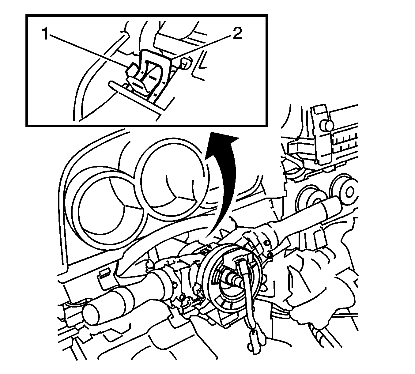
- Use pliers to hold the clamp (2) and raise the claw (1) with a screwdriver. Remove the following components as an assembly:
| • | The inflatable restraint coil |
| • | The steering wheel position sensor |
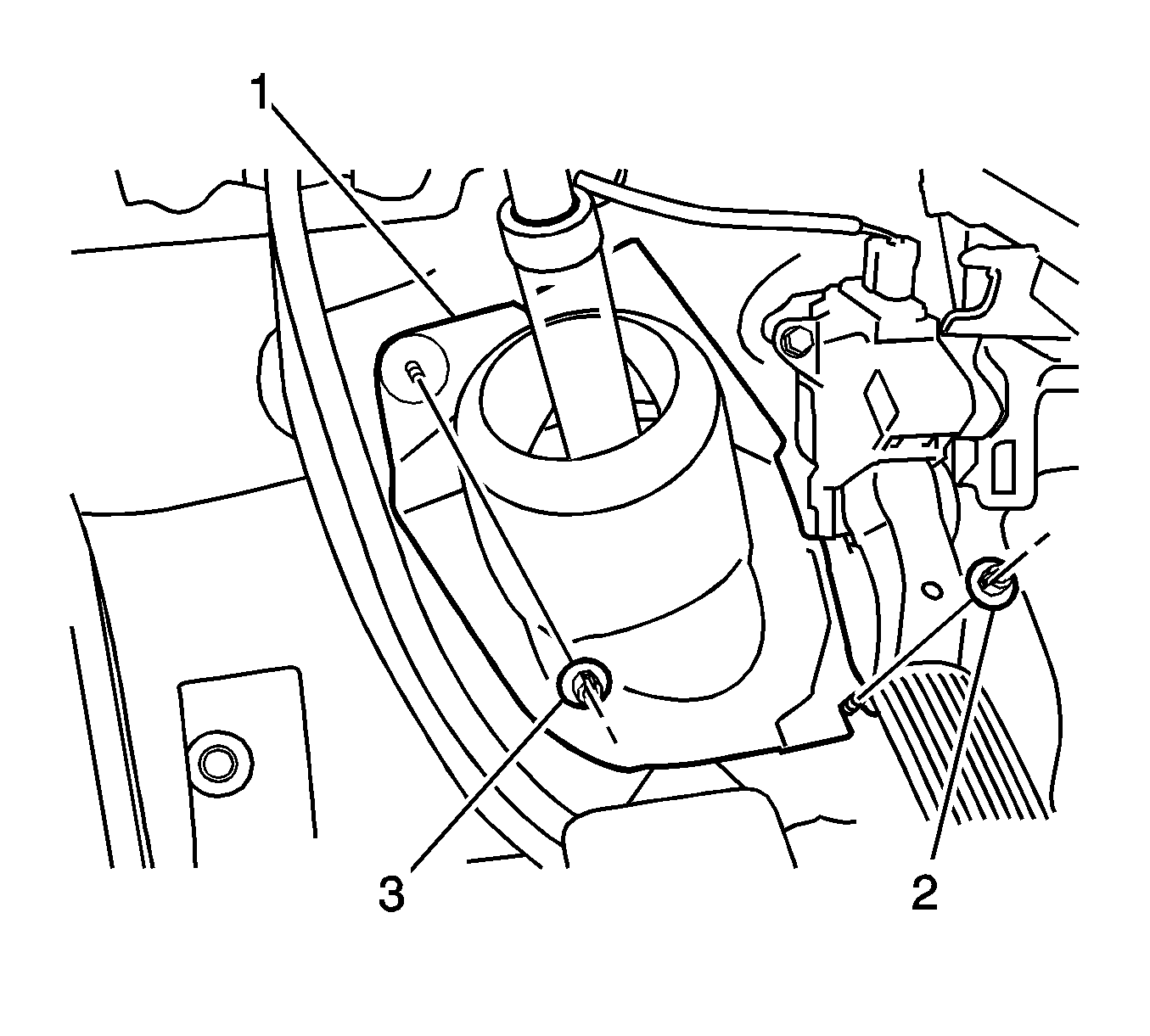
| • | Turn back the floor carpet, and remove the 2 clips (2, 3) and the column hole cover silencer sheet (1). |
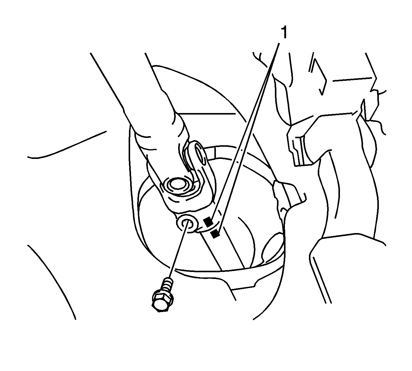
- If the vehicle has front-wheel drive, complete the following steps:
| 12.1. | Put match marks (1) on the upper intermediate shaft and on the lower intermediate shaft. |
| 12.3. | Separate the upper intermediate shaft from the lower intermediate shaft. |
- If the vehicle has all-wheel drive, complete the following steps:
| 13.1. | Put match marks on the intermediate shaft assembly and on the steering gear pinion shaft. |
| 13.3. | Separate the intermediate shaft assembly from the steering gear pinion shaft. |
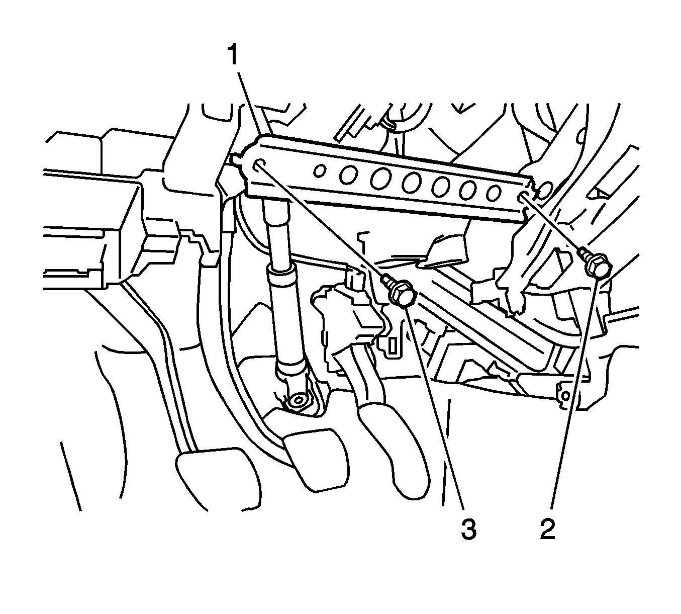
- Remove the 2 bolts (2, 3) and instrument panel sub reinforcement (1).
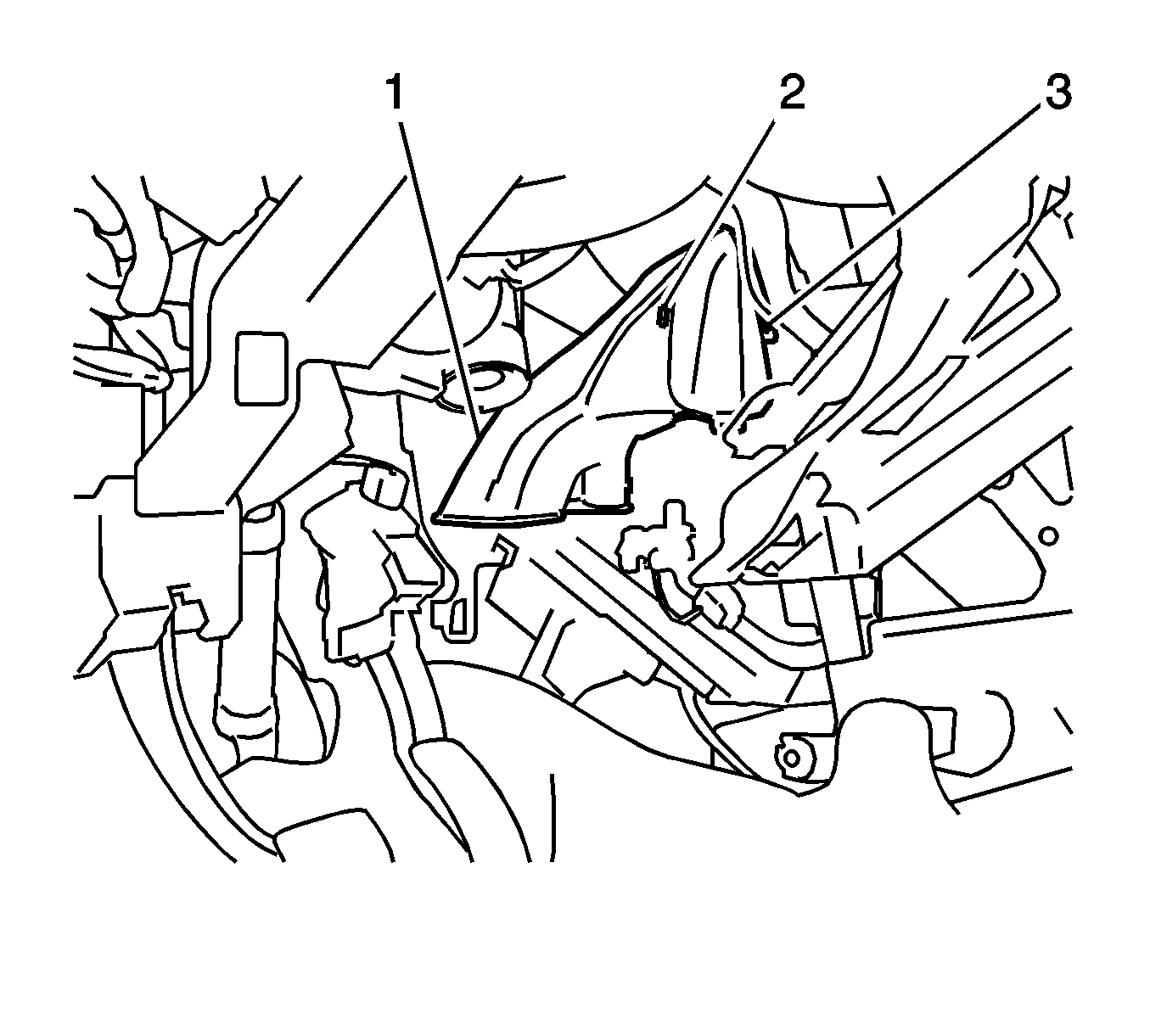
- Disengage the 2 claws (2, 3) and remove the air duct sub-assembly (1).
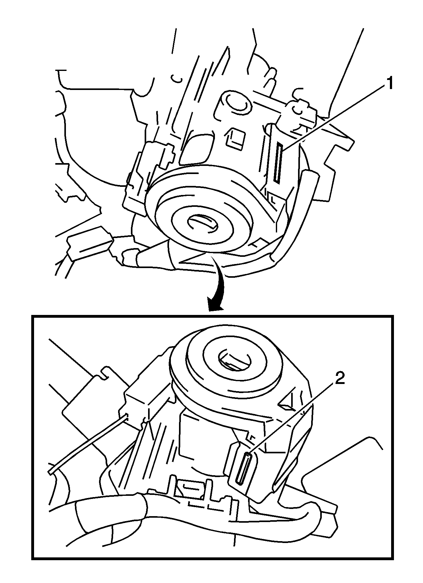
- Slide the transponder key amplifier to disengage the 2 claws (1, 2).
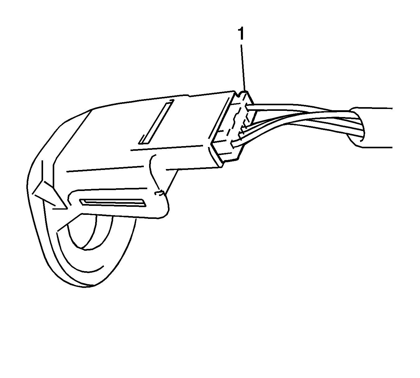
- Disconnect the connector (1) and remove the transponder key amplifier.
- Remove the stop lamp switch. Refer to
Stop Lamp Switch Replacement.
- Disconnect the connectors on the steering column.
- Separate the wire harness clamps from the steering column.
Caution: Once the steering column is removed from the vehicle, the column is extremely susceptible to damage. Dropping the column assembly on the end could collapse the steering shaft or loosen the plastic
injections, which maintain column rigidity. Leaning on the column assembly could cause the jacket to bend or deform. Any of the above damage could impair the columns collapsible design. Do NOT hammer on the end of the shaft, because hammering could loosen
the plastic injections, which maintain column rigidity. If you need to remove the steering wheel, refer to the Steering Wheel Replacement procedure in this section.
Note: Do not release the tilt lever when the steering column assembly is not installed on the vehicle.
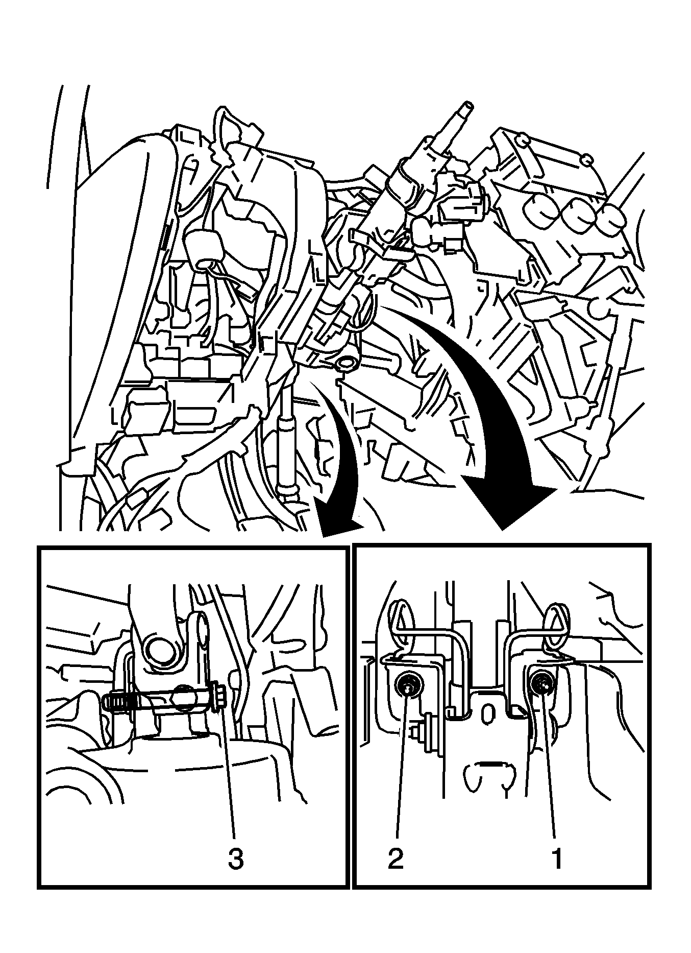
- Remove the bolt (3) and the 2 nuts (1, 2) from the steering column assembly.
- Remove the steering column and the intermediate shaft as an assembly.
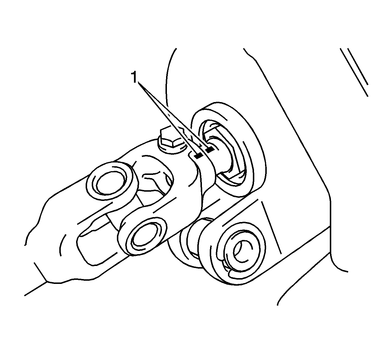
- Put match marks (1) on the intermediate shaft assembly and on the steering column assembly.
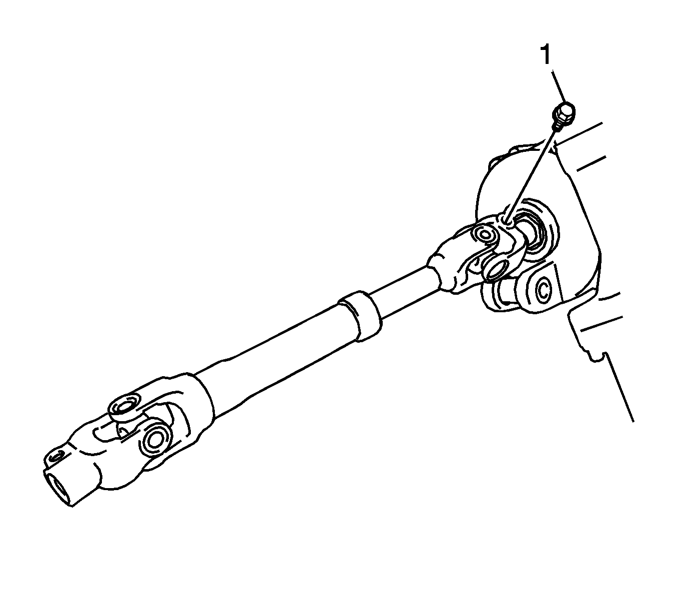
- Remove the bolt (1) and the intermediate shaft assembly from the steering column assembly.
- Remove the ignition lock cylinder. Refer to
Ignition Lock Cylinder Replacement.
- Remove the ignition switch. Refer to
Ignition and Start Switch Replacement.
- Remove the following components. Refer to
Ignition Lock Cylinder Case Replacement.
| • | The key interlock solenoid |
| • | The unlock warning switch |
| • | The ignition lock cylinder case |
Inspection Procedure
- Secure the steering column assembly in a vise.
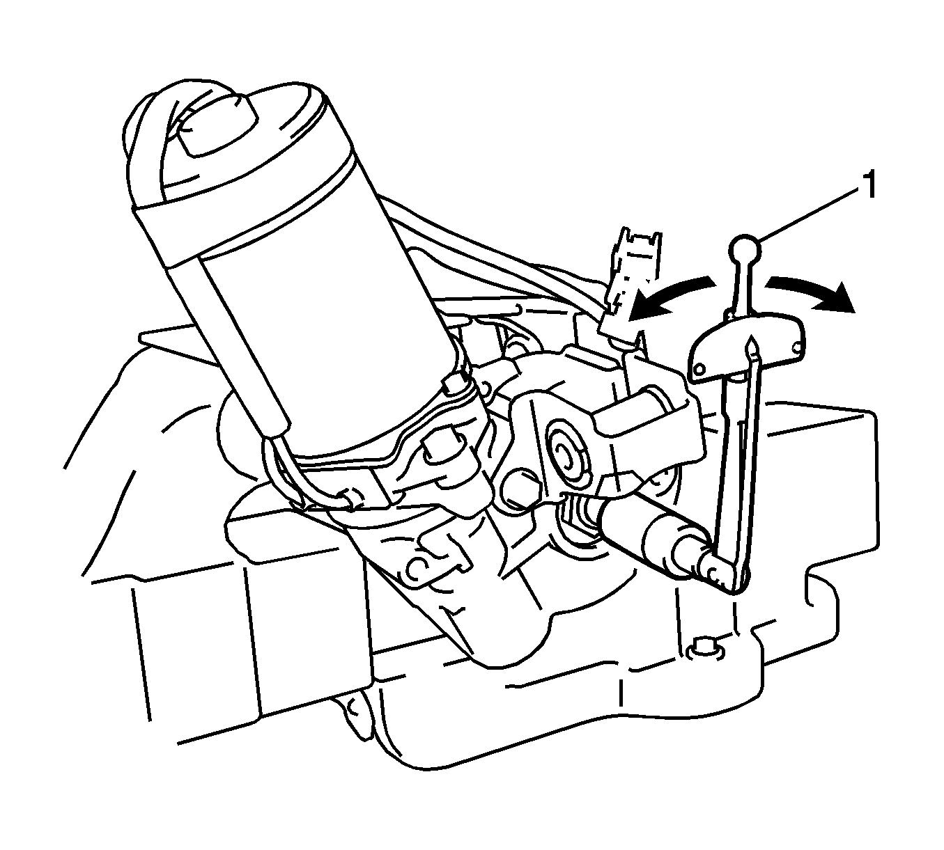
- Using a torque wrench (1), turn the main shaft and measure the preload.
Preload
0.8 to 1.2 N·m (7.1 to 10.6 lb in).
- If the preload is not as specified, replace the steering column assembly.
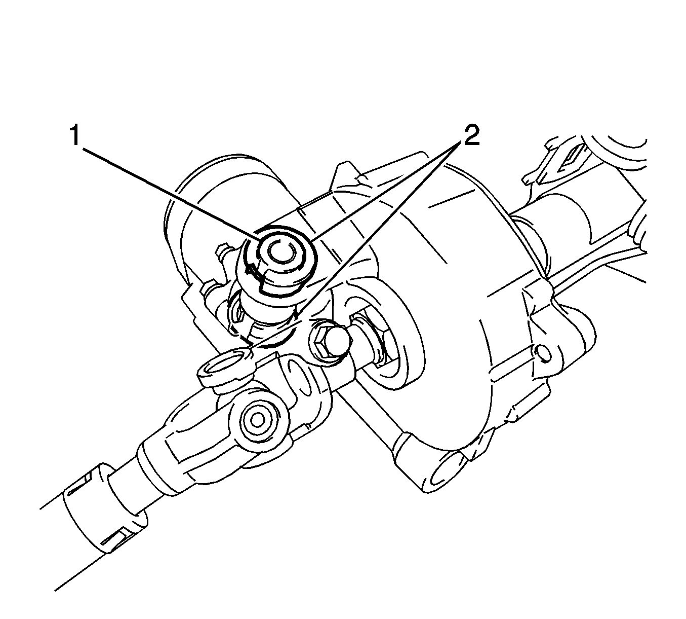
- Verify the collar (1) and the 2 bushings (2) are securely installed to the steering column assembly. If the collar or the bushings
are missing or damaged, replace the steering column assembly.
Installation Procedure
- Install the following components. Refer to
Ignition Lock Cylinder Case Replacement.
| • | The key interlock solenoid |
| • | The unlock warning switch |
| • | The ignition lock cylinder case |
- Install the ignition switch. Refer to
Ignition and Start Switch Replacement.
- Install the ignition lock cylinder. Refer to
Ignition Lock Cylinder Replacement.
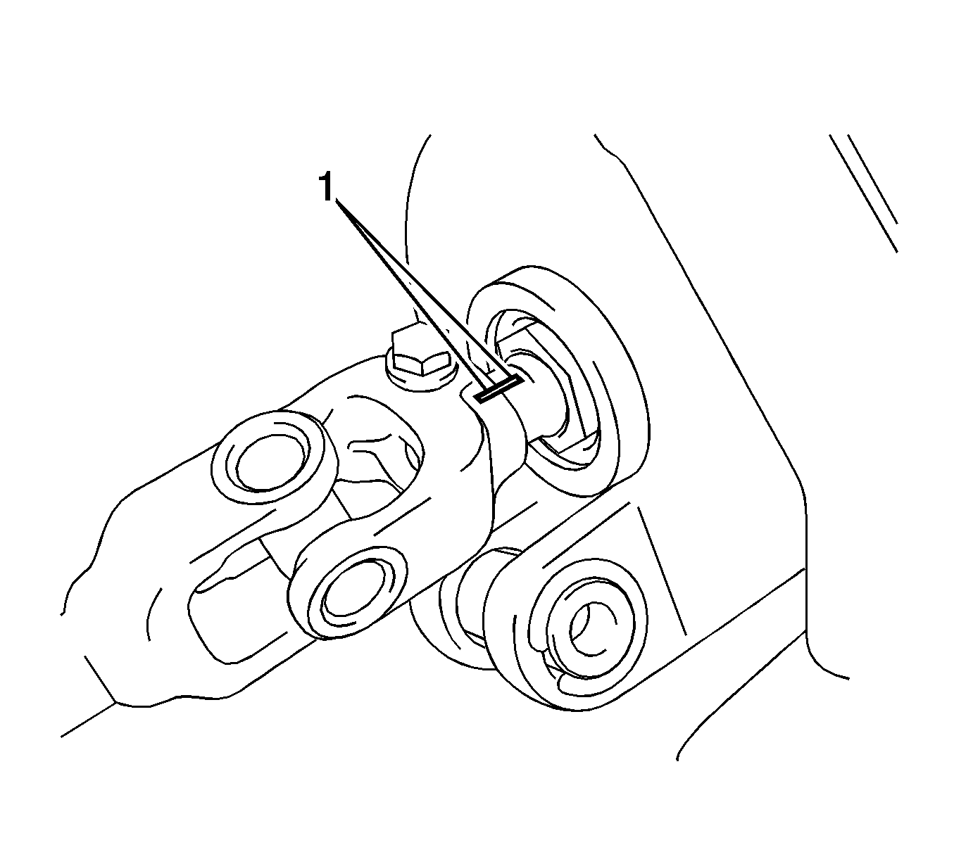
- Align the match marks (1) on the intermediate shaft assembly and on the steering column assembly.
Caution: Refer to Fastener Caution in the Preface section.

- Install the intermediate shaft bolt (1). Tighten the bolt to
35 N·m(26 lb ft).

Note: Do not line-up the bolt hole by prying on the collar or bushings. Only install the bolt in straight, without applying any force to the bushings.
- Install the steering column assembly with the bolt (3) and the 2 nuts (1, 2). Tighten the bolt and the nuts to
25 N·m(18 lb ft).
- Connect the connectors and engage the wire harness clamps to the steering column assembly.
- Ensure the front wheels are in the straight ahead position.

- If the vehicle has front-wheel drive, align the match marks (1) on the upper intermediate shaft and on the lower intermediate shaft.
- If the vehicle has all-wheel drive, align the match marks on the intermediate shaft and on the power steering gear pinion shaft.
- Install the bolt. Tighten the bolt to
35 N·m (26 lb ft).
- Install the stop lamp switch. Refer to
Stop Lamp Switch Replacement.

- Engage the 2 claws (2, 3) and install the air duct sub-assembly (1).

- Install the instrument panel sub reinforcement (1) with the 2 bolts (2, 3). Tighten the bolts to
24 N·m
(18 lb ft).

- Install the column hole cover silencer sheet (1) with the 2 clips (2, 3).
- Install the floor carpet.

- Connect the connector (1) to the transponder key amplifier.
- Align the transponder key amplifier with the steering column upper bracket. Tilt the amplifier slightly and slide the amplifier into position.
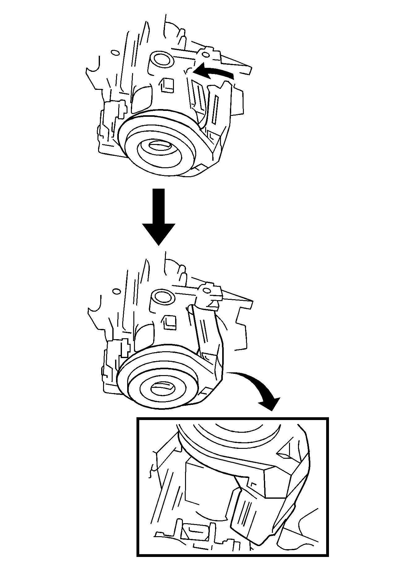
- Push the amplifier, and engage the 2 claws to install the amplifier to the steering column upper bracket.

- Using pliers, engage the claw (1) and install the following components as an assembly:
| • | The inflatable restraint coil |
| • | The steering wheel position sensor |
- Connect the connector to the steering wheel position sensor.
- Connect the connector to the inflatable restraint coil.
- Connect the connector to the wiper switch.
- Connect the connector to the turn signal switch.
- Install the steering column trim covers. Refer to
Steering Column Trim Covers Replacement.
- Install the instrument panel lower trim panel. Refer to
Instrument Panel Lower Trim Panel Replacement.
- Install the steering wheel assembly. Refer to
Steering Wheel Replacement.
- Install the inflatable restraint steering wheel module. Refer to
Inflatable Restraint Steering Wheel Module Replacement.
- Connect the negative battery cable. Refer to
Battery Negative Cable Disconnection and Connection.
- Calibrate the torque sensor zero point. Refer to
Steering Angle Sensor Initialization and Steering Shaft Torque Sensor Zero Point Calibration.


