Power Vacuum Brake Booster Replacement w/RPO M75
Caution: Refer to Brake Fluid Irritant Caution in the Preface section.
Notice: Refer to Brake Fluid Effects on Paint and Electrical Components Notice in the Preface section.
Removal Procedure
- Disconnect the negative battery cable. Refer to Battery Negative Cable Disconnection and Connection in Engine Electrical.
- Remove the cover from the underhood electrical center.
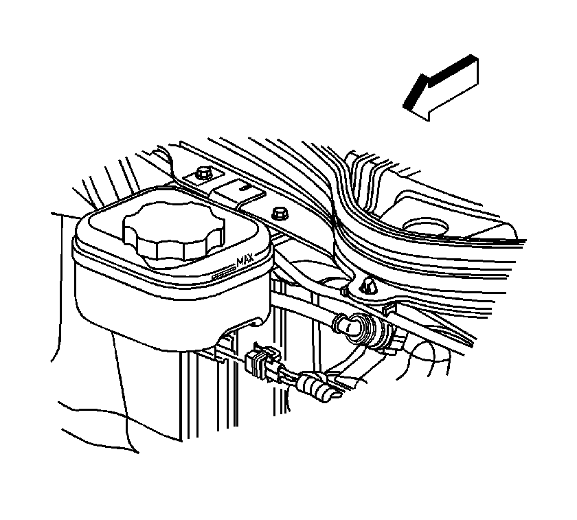
- Pull back on the connector position assurance (CPA) tab of the electrical connector, then disconnect the connector from the brake fluid level sensor.
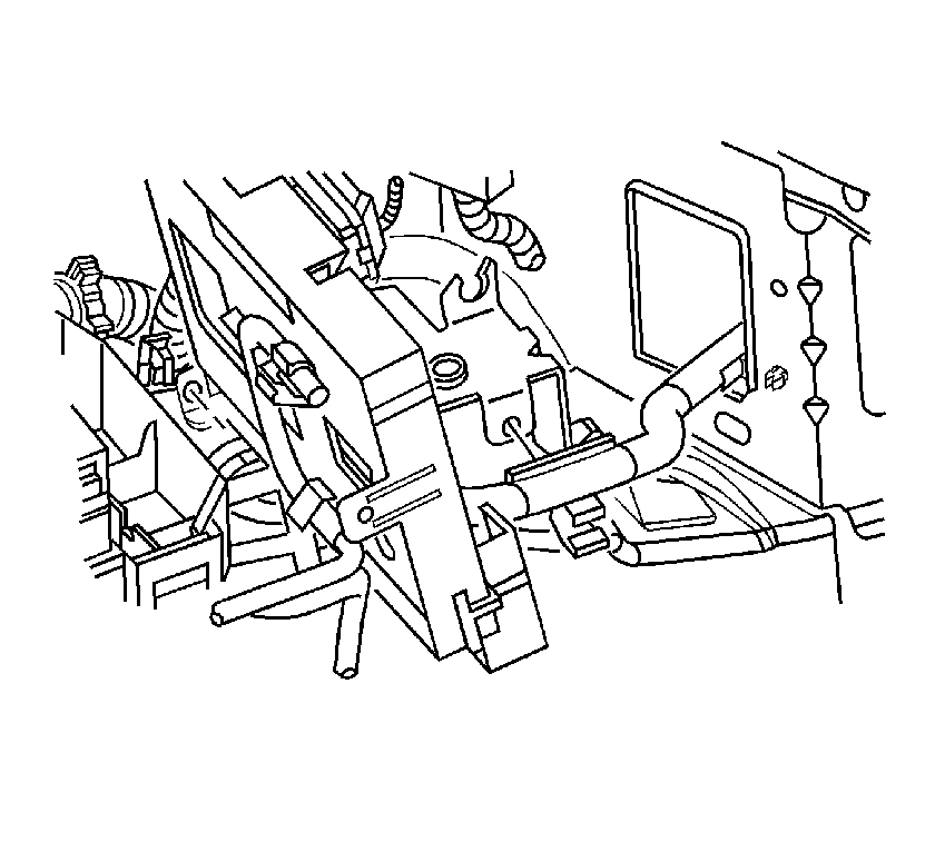
- Release the forward lamp harness retainer from the ABS modulator bracket, or the proportioning valve bracket, to allow the underhood electrical center to be repositioned adequately.
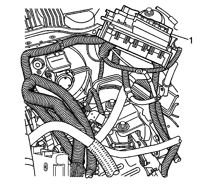
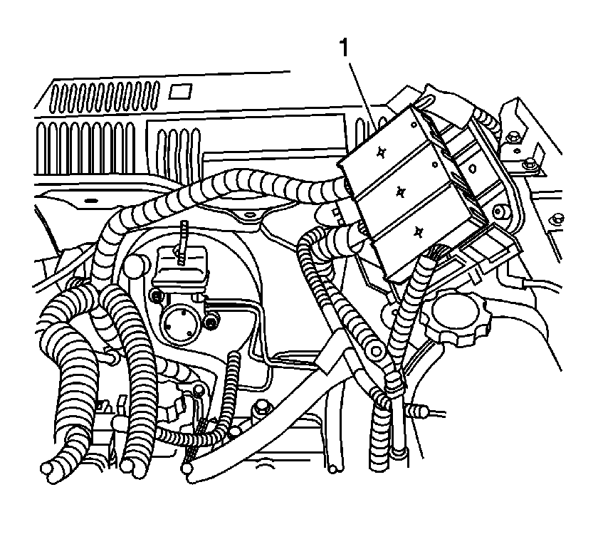
- Remove the underhood electrical center bracket from the vehicle and reposition the electrical center (1) to access the brake master cylinder and brake booster. Refer to Underhood Electrical Center or Junction Block Bracket Replacement in Wiring Systems.
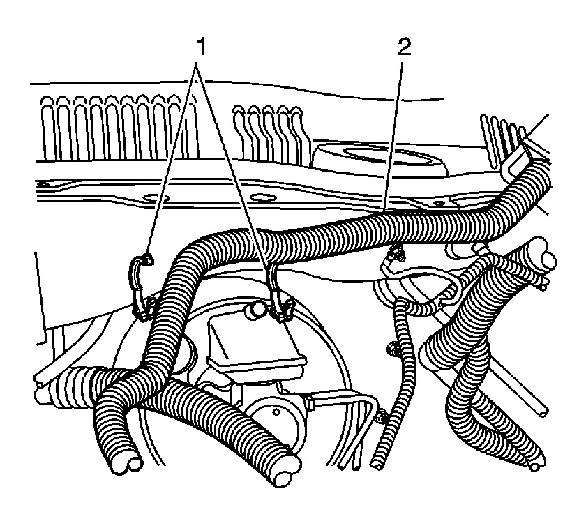
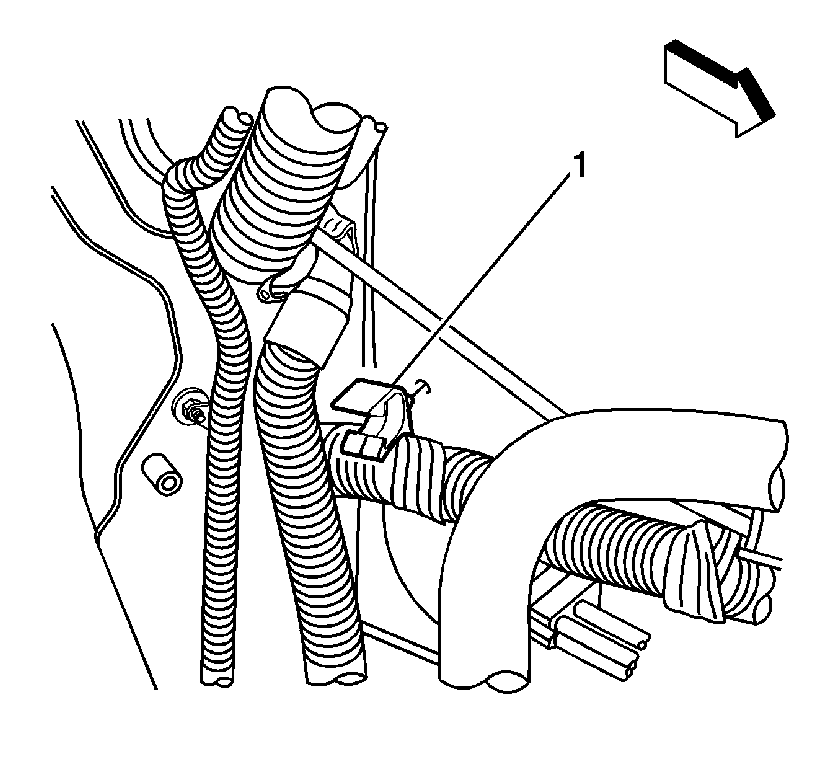
- Release the wiring harness (2) retainers (1) above the brake booster, to allow the electrical center to be repositioned adequately.
- Release the wiring harness retainer (1) from the side of the LH strut tower. Reposition the harness upward to allow clearance for booster removal.
- Release the brake master cylinder pipes from the 6-position pipe clip along the frame rail.
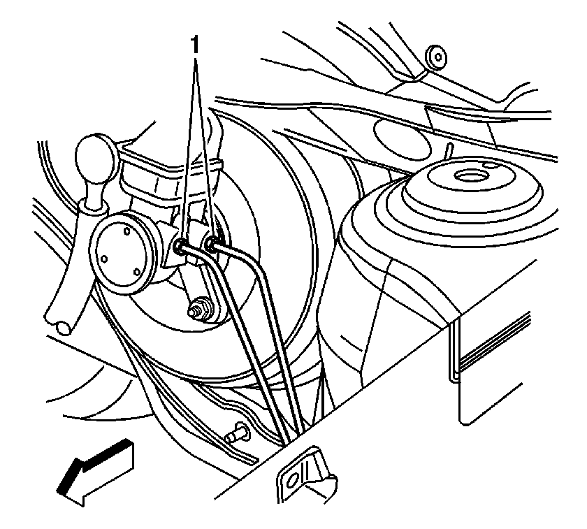
- Disconnect the brake pipes (1) from the master cylinder.
- Cap the open brake pipe fitting ends to prevent brake fluid loss and contamination.
- Remove the brake master cylinder auxiliary reservoir mounting bolts.
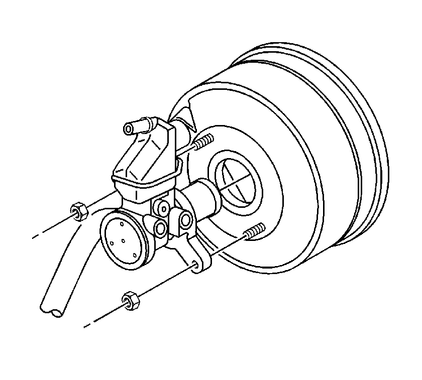
- Remove the master cylinder mounting nuts.
- Remove the master cylinder and the auxiliary reservoir, as an assembly, from the vacuum brake booster.
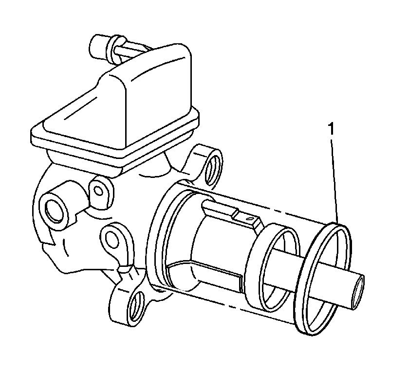
- Inspect the master cylinder-to-vacuum brake booster seal (1) for damage. Replace the seal (1) if necessary.
- Disconnect the electrical connector from the park/neutral position switch, and reposition the wiring harness toward the engine.
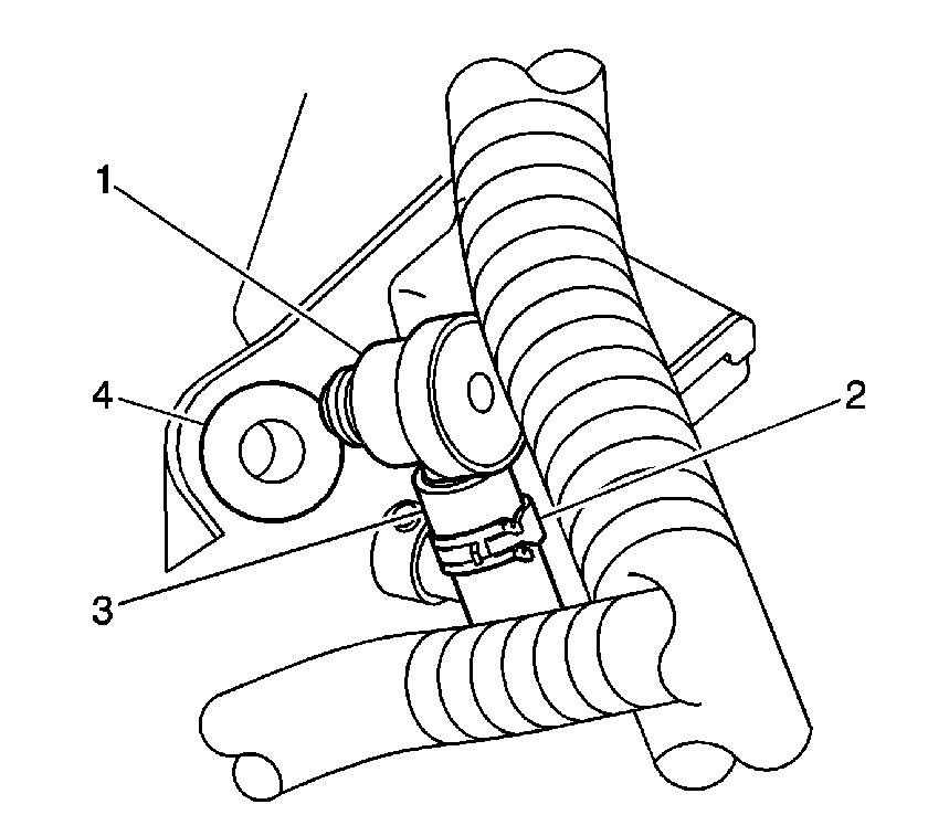
- Disconnect the vacuum check valve (1) from the brake booster and position aside the check valve (1) and vacuum hose (3).
- Disconnect the evaporative emission (EVAP) purge hose from the purge solenoid. Reposition the purge hose toward the engine. Refer to Evaporative Emission Hoses/Pipes Replacement - Engine in Engine Controls - 2.2L.
- Position the underhood electrical center (1) further toward the LH hood hinge, and secure the center in place.
- Install the engine support fixture. Refer to Engine Support Fixture in Engine Mechanical - 2.2L.
- Raise and support the vehicle. Refer to Lifting and Jacking the Vehicle in General Information.
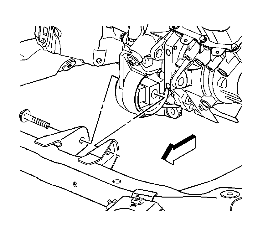
- Remove the thru-bolt from the front transmission mount.
- Remove the thru-bolt and heat shield from the rear transmission mount.
- Lower the vehicle. Leave the vehicle positioned on the hoist.
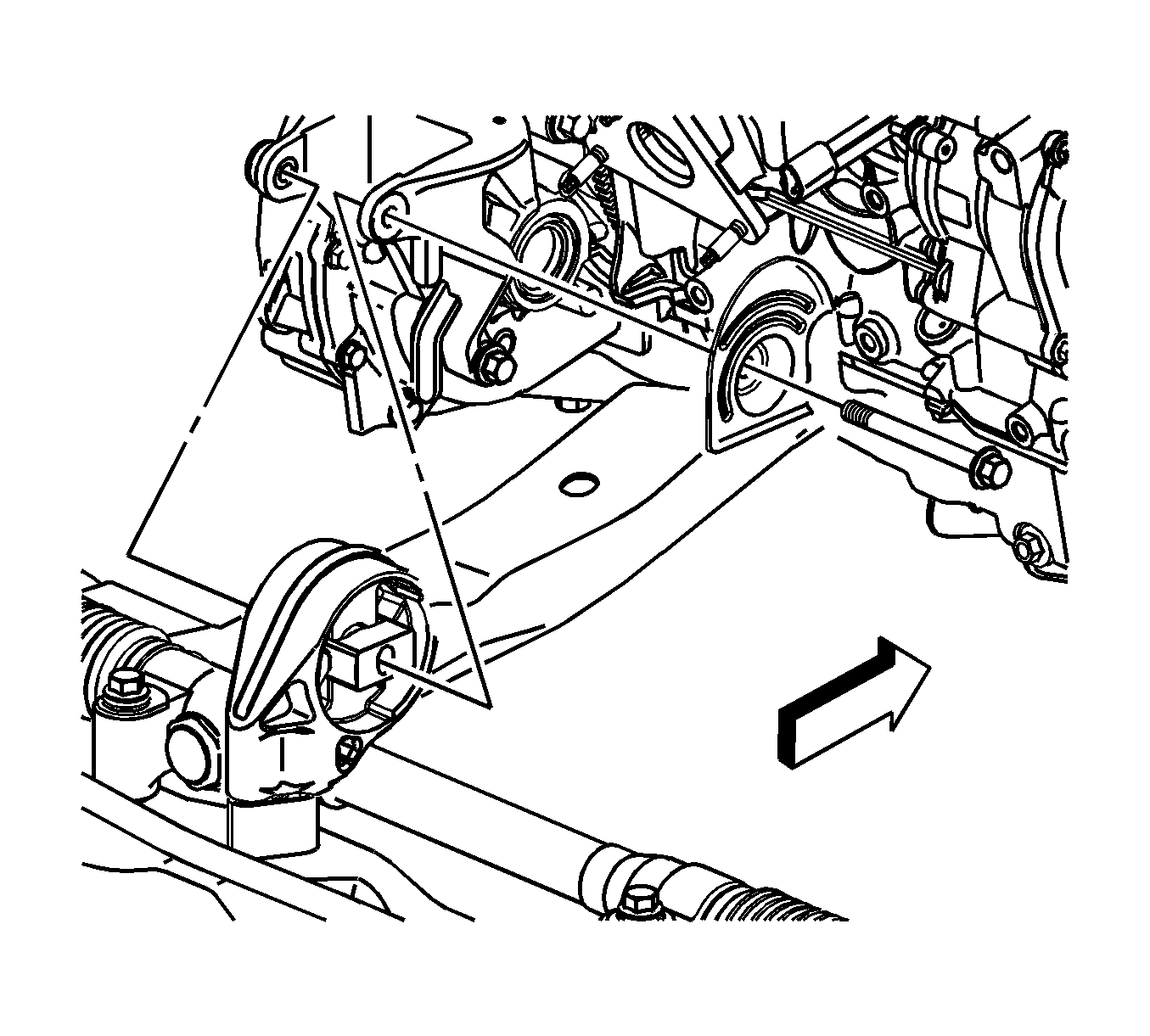
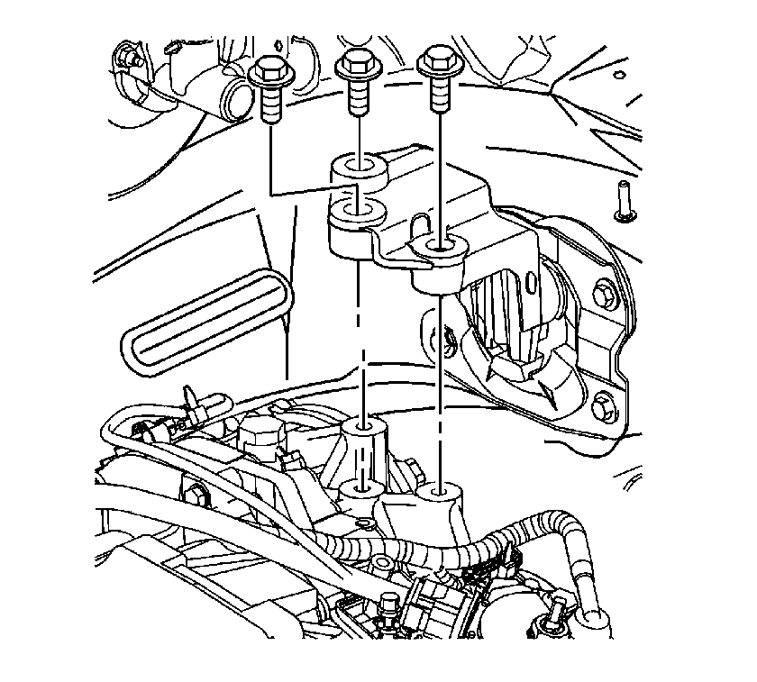
- Remove the transmission side mount-to-transmission bolts.
- Using the engine support fixture, slowly lower the transmission approximately 25 mm (1 in).
- Position the master cylinder pipes rearward and outboard, behind the wiring harness along the strut tower.
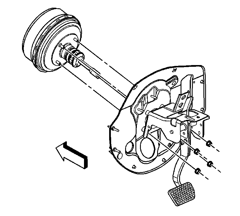
- Remove the accelerator pedal mounting nuts. Reposition the accelerator pedal to improve tool access to the LH, lower booster mounting nut. Refer to Accelerator Pedal Replacement in Engine Controls - 2.2L.
- Loosen the brake booster mounting nuts.
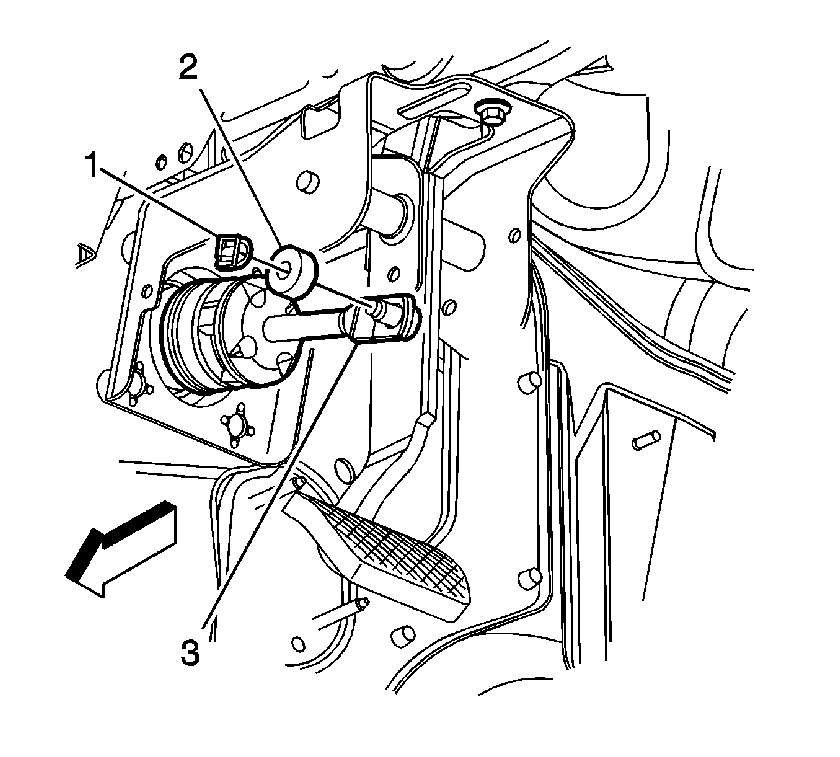
- Remove the retaining clip (1) and washer (2) from the brake pedal.
- Release the brake booster pushrod (3) from the brake pedal.
- Remove the brake booster mounting nuts.
- Pull the brake booster away from the dash panel, enough to clear the booster studs.
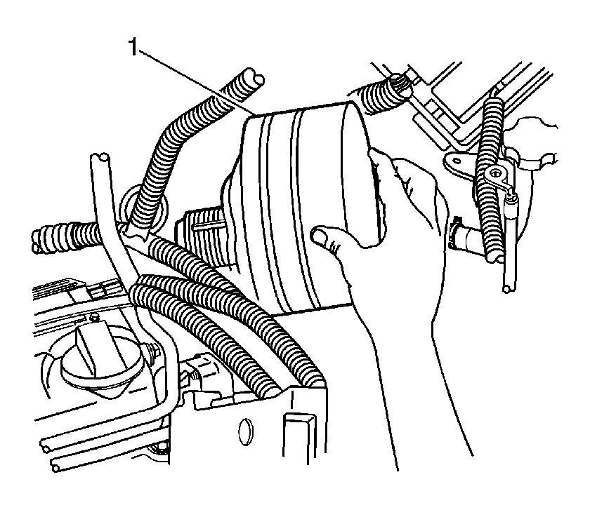
- With the booster (1) directed toward the coolant surge tank, continue to remove the booster (1) until the pushrod is just free of the opening in the dash panel.
- Turn the booster (1) to face the LH strut tower.
- Ensure that the rear of the booster (1) shell is clear of the valve body cover on top of the transmission.
- Rotate the booster (1), while it remains sideways to the dash panel, and carefully remove the booster (1) up and out from between the cowl and the transmission.
- Remove the brake booster (1) and the booster mounting gasket from the vehicle.
- Inspect the mounting gasket for damage and replace if necessary.
Important: Use care to ensure that no oil or contaminants enter the vacuum brake booster through the master cylinder opening. Cover the opening on the booster, if possible.
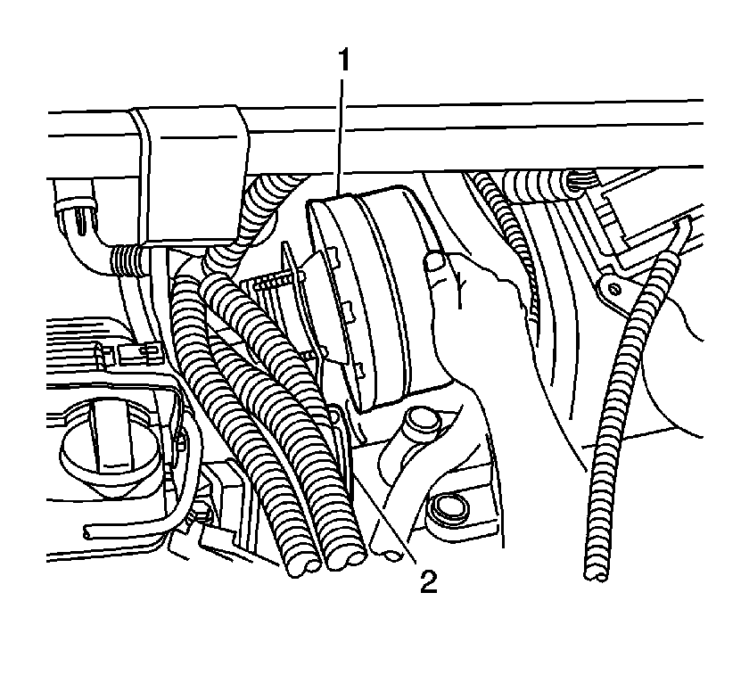
If necessary, lower the transmission slightly to aid with booster removal.
Installation Procedure
Notice: Internal components of this booster are not serviceable. The housing must not be unstaked and separated. Separating the housing will cause permanent deformation, preventing the booster from holding proper volume.
- Install the mounting gasket to the vacuum brake booster.
- Turn the booster (1) to face the LH strut tower.
- Ensure that the rear of the booster (1) shell is clear of the valve body cover on top of the transmission.
- Rotate the booster (1), while it remains sideways to the dash panel, and carefully install the booster (1) down and rearward in between the cowl and the transmission.
- With the booster (1) directed toward the coolant surge tank, install the booster (1) pushrod into the opening in the dash panel.
- Align the brake booster to the dash panel, and insert the booster studs through the dash.
- Loosely install the brake booster mounting nuts.
- Apply a thin coating of lithium grease to the pushrod pin on the brake pedal.
- Connect the brake booster pushrod (3) to the brake pedal.
- Install the washer (2) and retaining clip (1) to the brake pedal.
- Tighten the vacuum brake booster mounting nuts.
- Install the accelerator pedal into position and install the pedal mounting nuts. Refer to Accelerator Pedal Replacement in Engine Controls - 2.2L.
- Using the engine support fixture, slowly raise the transmission into the fully installed position.
- Carefully install the transmission side mount-to-transmission bolts by hand. Do NOT force the bolts.
- Using ONLY HAND TOOLS, Tighten the transmission side mount-to-transmission bolts. Refer to Transmission Mount Replacement - Side in Automatic Transmission - VT25-E.
- With the vehicle still positioned on the hoist, raise and support the vehicle.
- Install the heat shield and thru-bolt to the rear transmission mount. Hand-start the bolt. Do NOT tighten the bolt.
- Install the thru-bolt to the front transmission mount. Hand-start the bolt. Do NOT tighten the bolt.
- Tighten the transmission mount bolts in sequence. Refer to Transmission Rear Mount Replacement and Transmission Front Mount Replacement in Automatic Transmission - VT25-E.
- Lower the vehicle.
- Remove the engine support fixture. Refer to Engine Support Fixture in Engine Mechanical - 2.2L.
- Connect the EVAP purge hose to the purge solenoid. Refer to Evaporative Emission Hoses/Pipes Replacement - Engine in Engine Controls - 2.2L.
- Connect the vacuum check valve (1) with hose (3) to the brake booster.
- Connect the electrical connector to the park/neutral position switch.
- Check to ensure that the master cylinder-to-vacuum brake booster seal (1) is properly seated into the recessed groove on the master cylinder.
- Install the master cylinder and the auxiliary reservoir, as an assembly, to the vacuum brake booster.
- Install the brake master cylinder mounting nuts.
- Install the brake master cylinder auxiliary reservoir mounting bolts.
- Secure the master cylinder pipes to the 6-position pipe clip along the frame rail.
- Position the master cylinder pipes to the master cylinder ports.
- Remove the caps from the brake pipe ends.
- Connect the brake pipe fittings (1) at the master cylinder.
- Secure the wiring harness retainer (1) to the side of the LH strut tower.
- Install the wiring harness (2) to the retainers (1) above the brake booster, and secure the retainers (1).
- Install the underhood electrical center bracket to the vehicle and install the electrical center (1) into position on the bracket. Refer to Underhood Electrical Center or Junction Block Bracket Replacement in Wiring Systems.
- Secure the forward lamp harness retainer to the ABS modulator bracket, or the proportioning valve bracket.
- Connect the electrical connector to the brake fluid level sensor, then press forward on the CPA tab of the connector to secure.
- Install the cover to the underhood electrical center.
- Connect the negative battery cable. Refer to Battery Negative Cable Disconnection and Connection in Engine Electrical.
- Bleed the hydraulic brake system. Refer to Hydraulic Brake System Bleeding .


Notice: Refer to Fastener Notice in the Preface section.
Tighten
Tighten the nuts to 25 N·m (18 lb ft).


Important: A small amount of denatured alcohol can be used as an assembly aid when installing the vacuum check valve. Do NOT use soap.


Tighten
Tighten the nuts to 20 N·m (15 lb ft).
Tighten
Tighten the bolts to 10 N·m (89 lb in).

Tighten
Tighten the fittings to 18 N·m (13 lb ft).


Power Vacuum Brake Booster Replacement w/Manual Transmission
Caution: Refer to Brake Fluid Irritant Caution in the Preface section.
Notice: Refer to Brake Fluid Effects on Paint and Electrical Components Notice in the Preface section.
Removal Procedure
- Disconnect the negative battery cable. Refer to Battery Negative Cable Disconnection and Connection .
- Remove the cover from the underhood electrical center.
- Pull back on the connector position assurance (CPA) tab of the electrical connector, then disconnect the connector from the brake fluid level sensor.
- Remove the underhood electrical center bracket from the vehicle and reposition the electrical center (1) to access the brake master cylinder and brake booster. Refer to Underhood Electrical Center or Junction Block Bracket Replacement .
- Remove the brake master cylinder auxiliary reservoir. Refer to Brake Master Cylinder Auxiliary Reservoir Replacement .
- Release the brake master cylinder pipes from the 6-position pipe clip along the frame rail.
- Remove the master cylinder mounting nuts.
- Remove the master cylinder from the vacuum brake booster. Carefully reposition the master cylinder up and outboard, with the brake pipes still attached. Secure the master cylinder in position.
- Inspect the master cylinder-to-vacuum brake booster seal (1) for damage. Replace the seal (1) if necessary.
- Disconnect the vacuum check valve (1) from the brake booster and position aside the check valve (1) and vacuum hose (3).
- Remove the accelerator pedal mounting nuts. Reposition the accelerator pedal to improve tool access to the LH, lower booster mounting nut. Refer to Accelerator Pedal Position Sensor Replacement .
- Loosen the brake booster mounting nuts.
- Remove the retaining clip (1) and washer (2) from the brake pedal.
- Release the brake booster pushrod (3) from the brake pedal.
- Remove the brake booster mounting nuts.
- Remove the brake booster and the booster mounting gasket from the vehicle.
- Inspect the mounting gasket for damage and replace if necessary.


Installation Procedure
Notice: Internal components of this booster are not serviceable. The housing must not be unstaked and separated. Separating the housing will cause permanent deformation, preventing the booster from holding proper volume.
- Install the mounting gasket to the vacuum brake booster.
- Install the brake booster to the dash panel.
- Loosely install the brake booster mounting nuts.
- Apply a thin coating of lithium grease to the pushrod pin on the brake pedal.
- Connect the brake booster pushrod (3) to the brake pedal.
- Install the washer (2) and retaining clip (1) to the brake pedal.
- Tighten the vacuum brake booster mounting nuts.
- Install the accelerator pedal into position and install the pedal mounting nuts. Refer to Accelerator Pedal Position Sensor Replacement .
- Connect the vacuum check valve (1) with hose (3) to the brake booster.
- Check to ensure that the master cylinder-to-vacuum brake booster seal (1) is properly seated into the recessed groove on the master cylinder.
- Install the master cylinder with the brake pipes, to the vacuum brake booster.
- Install the brake master cylinder mounting nuts.
- Secure the brake master cylinder pipes to the 6-position pipe clip along the frame rail.
- Install the brake master cylinder auxiliary reservoir. Refer to Brake Master Cylinder Auxiliary Reservoir Replacement .
- Install the underhood electrical center bracket to the vehicle and install the electrical center (1) into position on the bracket. Refer to Underhood Electrical Center or Junction Block Bracket Replacement .
- Connect the electrical connector to the brake fluid level sensor, then press forward on the CPA tab of the connector to secure.
- Install the cover to the underhood electrical center.
- Connect the negative battery cable. Refer to Battery Negative Cable Disconnection and Connection .


Notice: Refer to Fastener Notice in the Preface section.
Tighten
Tighten the nuts to 25 N·m (18 lb ft).

Important: A small amount of denatured alcohol can be used as an assembly aid when installing the vacuum check valve. Do NOT use soap.


Notice: Refer to Fastener Notice in the Preface section.
Tighten
Tighten the nuts to 20 N·m (15 lb ft).


